2009 SUBARU TRIBECA stop start
[x] Cancel search: stop startPage 1193 of 2453
![SUBARU TRIBECA 2009 1.G Service Workshop Manual EN(H6DO)(diag)-32
Subaru Select Monitor
ENGINE (DIAGNOSTICS)
7. LED OPERATION MODE FOR ENGINE
1) On the «Main Menu» display screen, select the {Each System Check} and press the [YES] key.
2) On the SUBARU TRIBECA 2009 1.G Service Workshop Manual EN(H6DO)(diag)-32
Subaru Select Monitor
ENGINE (DIAGNOSTICS)
7. LED OPERATION MODE FOR ENGINE
1) On the «Main Menu» display screen, select the {Each System Check} and press the [YES] key.
2) On the](/manual-img/17/7322/w960_7322-1192.png)
EN(H6DO)(diag)-32
Subaru Select Monitor
ENGINE (DIAGNOSTICS)
7. LED OPERATION MODE FOR ENGINE
1) On the «Main Menu» display screen, select the {Each System Check} and press the [YES] key.
2) On the «System Selection Menu» display screen, select the {Engine} and press the [YES] key.
3) Press the [YES] key after the information of engine type has been displayed.
4) On the «Engine Diagnosis» display screen, select the {Current Data Display/Save}, and then press the
[YES] key.
5) On the «Data Display» screen, select the {Data LED Display} and press the [YES] key.
6) Using the scroll key, scroll the display screen up or down until the desired data is shown.
•A list of the support data is shown in the following table.
NOTE:
For detailed operation procedure, refer to the “SUBARU SELECT MONITOR OPERATION MANUAL”.
Description Display Message When LED “ON” required
Te s t m o d e s i g n a l Te s t m o d e t e r m i n a l D c h e c k / U c h e c k D c h e c k
Neutral position switch signal Neutral SW Neutral/Other than neutral Neutral
Idle switch signal Soft idle SW Idle/Other than idle In idle
Ignition switch signal Ignition SW ON Input/OFF Input ON input
Pow er s te e r in g sw it c h s ig n al Pow er s te e r in g S W ON I np u t/ O FF I np u t ON i np ut
Air conditioning switch signal A/C SW ON Input/OFF Input ON input
Starter switch signal Starter SW ON Input/OFF Input ON input
Fr o nt ox yg e n mo n it o r 1 Ft O 2 mo n it o r 1 Le a n/ Ri ch Ric h
Fr o nt ox yg e n mo n it o r 2 Ft O 2 mo n it o r 2 Le a n/ Ri ch Ric h
Knocking signal Knock signal Yes/No Yes
Crankshaft position sensor signal Crankshaft angle signal Yes/No Yes
Camshaft position sensor signal Camshaft angle signal Yes/No Yes
Rear defogger switch signal Rear defogger SW ON Input/OFF Input ON input
Blower fan switch signal Blower fan SW ON Input/OFF Input ON input
Light switch signal Light SW ON Input/OFF Input ON input
Wiper switch signal Wiper SW ON Input/OFF Input ON input
A/C middle pressure switch signal A/C middle pressure SW ON Input/OFF Input ON input
Air conditioner compressor relay sig-
nalCompressor relay ON output/OFF output ON output
Drain valve signal Vent. Solenoid Valve ON or OFF When drain valve is ON.
AT r e t a r d a n g l e d e m a n d s i g n a l AT r e t a r d a n g l e d e m a n d Ye s / N o Ye s
AT f u e l c u t s i g n a l AT f u e l c u t Ye s / N o Ye s
VDC torque down prohibition output Torque down output ON/OFF Prohibition
VDC torque down demand Torque down demand Yes/No Yes
AT c o o r d i n a t e p e r m i s s i o n s i g n a lAT c o o r d i n a t e p e r m i s s i o n
signalON/OFF Permission
Electronic throttle control motor relay
signalETC motor relay ON/OFF ON
Stop light switch signal Stop SW ON Input/OFF Input ON input
SET/COAST switch signal SET/CST SW ON Input/OFF Input ON input
RESUME/ACCEL switch signal RES/ACC SW ON Input/OFF Input ON input
Brake switch signal Brake SW ON Input/OFF Input ON input
Main switch signal Main SW ON Input/OFF Input ON input
Body integrated unit data reception Body Int. Unit Data Yes/No Yes
Body integrated unit counter update Body Int. Unit Count Yes/No Yes
Cruise control cancel switch signal CC Cancel SW ON Input/OFF Input ON input
Va r i a b l e va l v e l i f t d i a g n o s i s o i l p r e s -
sure switch signal 1Oil Temperature SW1 ON/OFF ON
Va r i a b l e va l v e l i f t d i a g n o s i s o i l p r e s -
sure switch signal 2Oil Temperature SW2 ON/OFF ON
Page 1197 of 2453
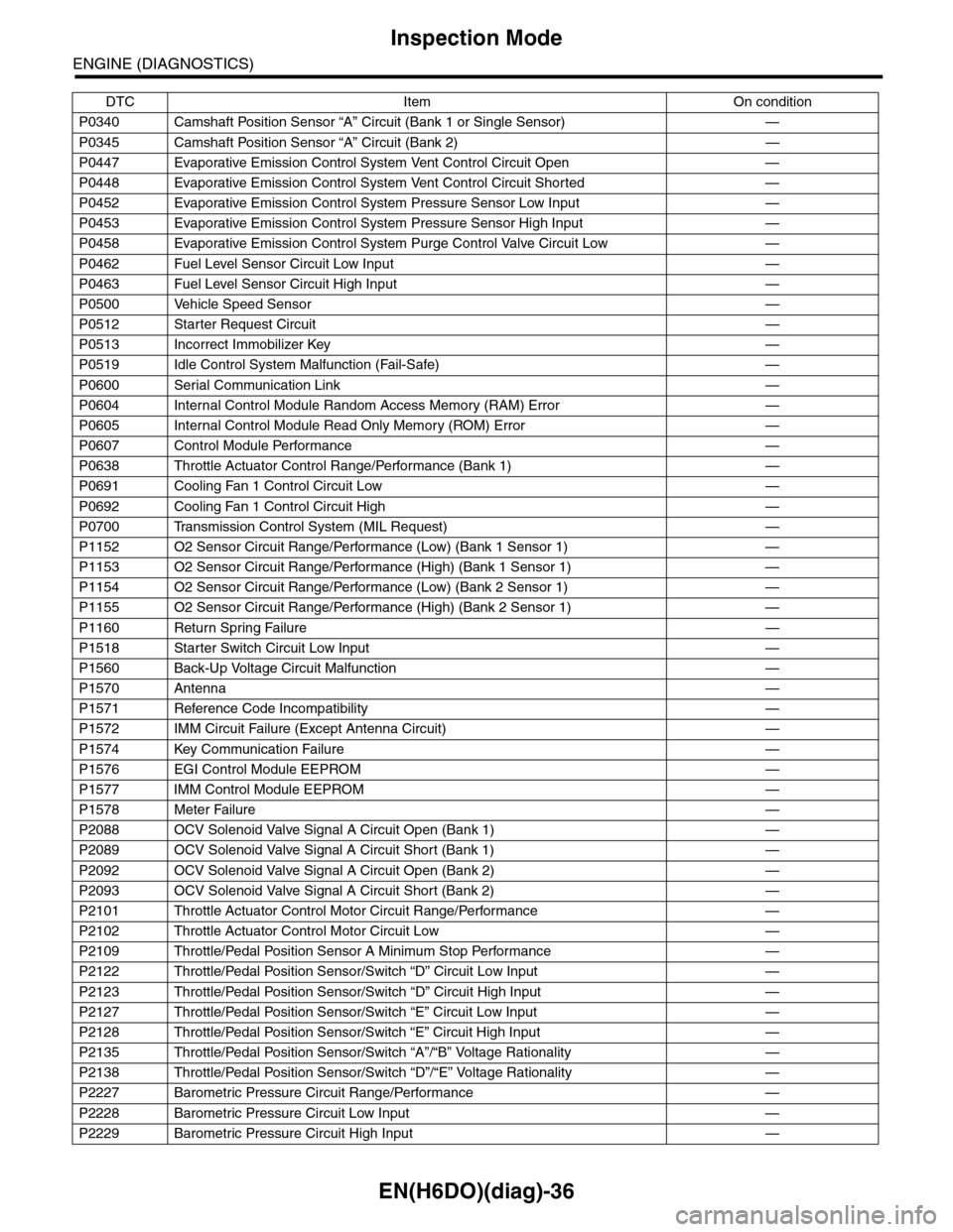
EN(H6DO)(diag)-36
Inspection Mode
ENGINE (DIAGNOSTICS)
P0340 Camshaft Position Sensor “A” Circuit (Bank 1 or Single Sensor) —
P0345 Camshaft Position Sensor “A” Circuit (Bank 2) —
P0447 Evaporative Emission Control System Vent Control Circuit Open —
P0448 Evaporative Emission Control System Vent Control Circuit Shorted —
P0452 Evaporative Emission Control System Pressure Sensor Low Input —
P0453 Evaporative Emission Control System Pressure Sensor High Input —
P0458 Evaporative Emission Control System Purge Control Valve Circuit Low —
P0462 Fuel Level Sensor Circuit Low Input —
P0463 Fuel Level Sensor Circuit High Input —
P0500 Vehicle Speed Sensor—
P0512 Starter Request Circuit—
P0513 Incorrect Immobilizer Key —
P0519 Idle Control System Malfunction (Fail-Safe) —
P0600 Serial Communication Link —
P0604 Internal Control Module Random Access Memory (RAM) Error —
P0605 Internal Control Module Read Only Memory (ROM) Error —
P0607 Control Module Performance —
P0638 Throttle Actuator Control Range/Performance (Bank 1) —
P0691 Cooling Fan 1 Control Circuit Low —
P0692 Cooling Fan 1 Control Circuit High —
P0700 Transmission Control System (MIL Request) —
P1152 O2 Sensor Circuit Range/Performance (Low) (Bank 1 Sensor 1) —
P1153 O2 Sensor Circuit Range/Performance (High) (Bank 1 Sensor 1) —
P1154 O2 Sensor Circuit Range/Performance (Low) (Bank 2 Sensor 1) —
P1155 O2 Sensor Circuit Range/Performance (High) (Bank 2 Sensor 1) —
P1160 Return Spring Failure—
P1518 Starter Switch Circuit Low Input —
P1560 Back-Up Voltage Circuit Malfunction —
P1570 Antenna—
P1571 Reference Code Incompatibility —
P1572 IMM Circuit Failure (Except Antenna Circuit) —
P1574 Key Communication Failure —
P1576 EGI Control Module EEPROM —
P1577 IMM Control Module EEPROM —
P1578 Meter Failure—
P2088 OCV Solenoid Valve Signal A Circuit Open (Bank 1) —
P2089 OCV Solenoid Valve Signal A Circuit Short (Bank 1) —
P2092 OCV Solenoid Valve Signal A Circuit Open (Bank 2) —
P2093 OCV Solenoid Valve Signal A Circuit Short (Bank 2) —
P2101 Throttle Actuator Control Motor Circuit Range/Performance —
P2102 Throttle Actuator Control Motor Circuit Low —
P2109 Throttle/Pedal Position Sensor A Minimum Stop Performance —
P2122 Throttle/Pedal Position Sensor/Switch “D” Circuit Low Input —
P2123 Throttle/Pedal Position Sensor/Switch “D” Circuit High Input —
P2127 Throttle/Pedal Position Sensor/Switch “E” Circuit Low Input —
P2128 Throttle/Pedal Position Sensor/Switch “E” Circuit High Input —
P2135 Throttle/Pedal Position Sensor/Switch “A”/“B” Voltage Rationality —
P2138 Throttle/Pedal Position Sensor/Switch “D”/“E” Voltage Rationality —
P2227 Barometric Pressure Circuit Range/Performance —
P2228 Barometric Pressure Circuit Low Input —
P2229 Barometric Pressure Circuit High Input —
DTC Item On condition
Page 1201 of 2453
EN(H6DO)(diag)-40
Drive Cycle
ENGINE (DIAGNOSTICS)
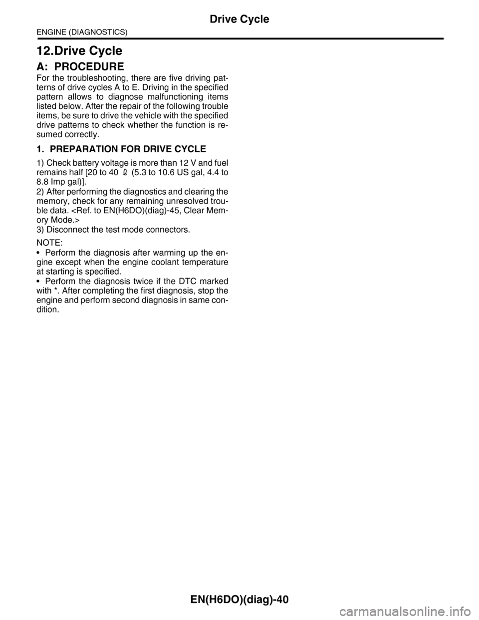
12.Drive Cycle
A: PROCEDURE
For the troubleshooting, there are five driving pat-
terns of drive cycles A to E. Driving in the specified
pattern allows to diagnose malfunctioning items
listed below. After the repair of the following trouble
items, be sure to drive the vehicle with the specified
drive patterns to check whether the function is re-
sumed correctly.
1. PREPARATION FOR DRIVE CYCLE
1) Check battery voltage is more than 12 V and fuel
remains half [20 to 40 2 (5.3 to 10.6 US gal, 4.4 to
8.8 Imp gal)].
2) After performing the diagnostics and clearing the
memory, check for any remaining unresolved trou-
ble data.
3) Disconnect the test mode connectors.
NOTE:
•Perform the diagnosis after warming up the en-
gine except when the engine coolant temperature
at starting is specified.
•Perform the diagnosis twice if the DTC marked
with *. After completing the first diagnosis, stop the
engine and perform second diagnosis in same con-
dition.
Page 1669 of 2453
GD(H6DO)-57
Diagnostic Trouble Code (DTC) Detecting Criteria
GENERAL DESCRIPTION
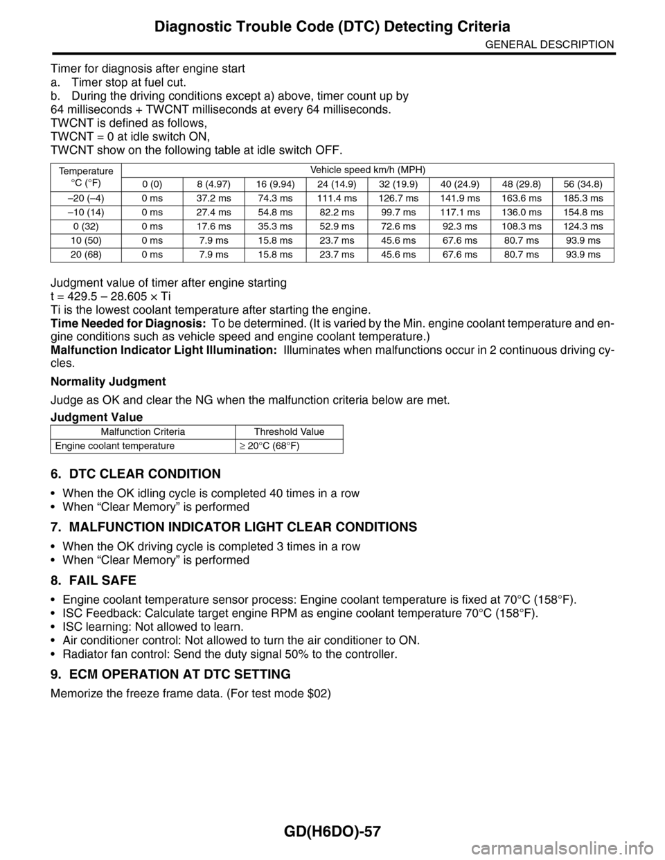
Timer for diagnosis after engine start
a. Timer stop at fuel cut.
b. During the driving conditions except a) above, timer count up by
64 milliseconds + TWCNT milliseconds at every 64 milliseconds.
TWCNT is defined as follows,
TWCNT = 0 at idle switch ON,
TWCNT show on the following table at idle switch OFF.
Judgment value of timer after engine starting
t = 429.5 – 28.605 × Ti
Ti is the lowest coolant temperature after starting the engine.
Time Needed for Diagnosis: To be determined. (It is varied by the Min. engine coolant temperature and en-
gine conditions such as vehicle speed and engine coolant temperature.)
Malfunction Indicator Light Illumination: Illuminates when malfunctions occur in 2 continuous driving cy-
cles.
Normality Judgment
Judge as OK and clear the NG when the malfunction criteria below are met.
6. DTC CLEAR CONDITION
•When the OK idling cycle is completed 40 times in a row
•When “Clear Memory” is performed
7. MALFUNCTION INDICATOR LIGHT CLEAR CONDITIONS
•When the OK driving cycle is completed 3 times in a row
•When “Clear Memory” is performed
8. FAIL SAFE
•Engine coolant temperature sensor process: Engine coolant temperature is fixed at 70°C (158°F).
•ISC Feedback: Calculate target engine RPM as engine coolant temperature 70°C (158°F).
•ISC learning: Not allowed to learn.
•Air conditioner control: Not allowed to turn the air conditioner to ON.
•Radiator fan control: Send the duty signal 50% to the controller.
9. ECM OPERATION AT DTC SETTING
Memorize the freeze frame data. (For test mode $02)
Te m p e r a t u r e
°C (°F)
Ve h i c l e s p e e d k m / h ( M P H )
0 (0) 8 (4.97) 16 (9.94) 24 (14.9) 32 (19.9) 40 (24.9) 48 (29.8) 56 (34.8)
–20 (–4) 0 ms 37.2 ms 74.3 ms 111.4 ms 126.7 ms 141.9 ms 163.6 ms 185.3 ms
–10 (14) 0 ms 27.4 ms 54.8 ms 82.2 ms 99.7 ms 117.1 ms 136.0 ms 154.8 ms
0 (32) 0 ms 17.6 ms 35.3 ms 52.9 ms 72.6 ms 92.3 ms 108.3 ms 124.3 ms
10 (50) 0 ms 7.9 ms 15.8 ms 23.7 ms 45.6 ms 67.6 ms 80.7 ms 93.9 ms
20 (68) 0 ms 7.9 ms 15.8 ms 23.7 ms 45.6 ms 67.6 ms 80.7 ms 93.9 ms
Judgment Value
Malfunction Criteria Threshold Value
Engine coolant temperature≥ 20°C (68°F)
Page 1670 of 2453
GD(H6DO)-58
Diagnostic Trouble Code (DTC) Detecting Criteria
GENERAL DESCRIPTION
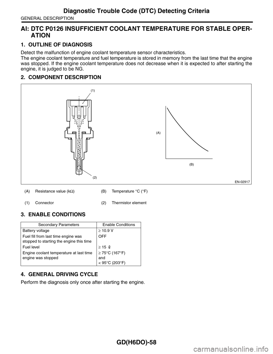
AI: DTC P0126 INSUFFICIENT COOLANT TEMPERATURE FOR STABLE OPER-
ATION
1. OUTLINE OF DIAGNOSIS
Detect the malfunction of engine coolant temperature sensor characteristics.
The engine coolant temperature and fuel temperature is stored in memory from the last time that the engine
was stopped. If the engine coolant temperature does not decrease when it is expected to after starting the
engine, it is judged to be NG.
2. COMPONENT DESCRIPTION
3. ENABLE CONDITIONS
4. GENERAL DRIVING CYCLE
Perform the diagnosis only once after starting the engine.
(A) Resistance value (kΩ)(B)Temperature °C (°F)
(1) Connector (2) Thermistor element
Secondary Parameters Enable Conditions
Battery voltage≥ 10.9 V
Fuel fill from last time engine was
stopped to starting the engine this time
OFF
Fuel level≥ 15 2
Engine coolant temperature at last time
engine was stopped
≥ 75°C (167°F)
and
< 95°C (203°F)
EN-02917
(A)
(2)
(1)
(B)
Page 1671 of 2453
GD(H6DO)-59
Diagnostic Trouble Code (DTC) Detecting Criteria
GENERAL DESCRIPTION
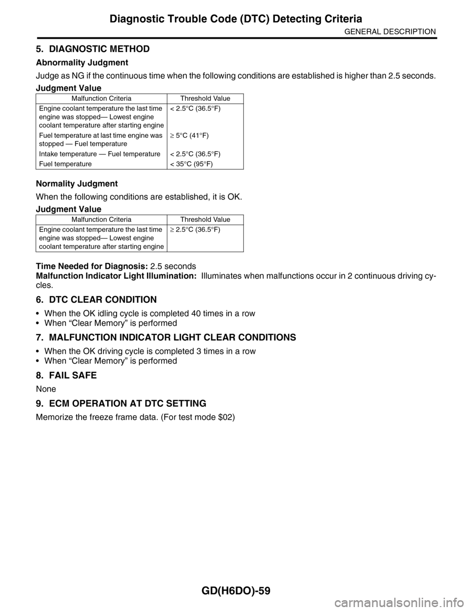
5. DIAGNOSTIC METHOD
Abnormality Judgment
Judge as NG if the continuous time when the following conditions are established is higher than 2.5 seconds.
Normality Judgment
When the following conditions are established, it is OK.
Time Needed for Diagnosis: 2.5 seconds
Malfunction Indicator Light Illumination: Illuminates when malfunctions occur in 2 continuous driving cy-
cles.
6. DTC CLEAR CONDITION
•When the OK idling cycle is completed 40 times in a row
•When “Clear Memory” is performed
7. MALFUNCTION INDICATOR LIGHT CLEAR CONDITIONS
•When the OK driving cycle is completed 3 times in a row
•When “Clear Memory” is performed
8. FAIL SAFE
None
9. ECM OPERATION AT DTC SETTING
Memorize the freeze frame data. (For test mode $02)
Judgment Value
Malfunction Criteria Threshold Value
Engine coolant temperature the last time
engine was stopped— Lowest engine
coolant temperature after starting engine
< 2.5°C (36.5°F)
Fuel temperature at last time engine was
stopped — Fuel temperature
≥ 5°C (41°F)
Intake temperature — Fuel temperature < 2.5°C (36.5°F)
Fuel temperature < 35°C (95°F)
Judgment Value
Malfunction Criteria Threshold Value
Engine coolant temperature the last time
engine was stopped— Lowest engine
coolant temperature after starting engine
≥ 2.5°C (36.5°F)
Page 1706 of 2453
GD(H6DO)-94
Diagnostic Trouble Code (DTC) Detecting Criteria
GENERAL DESCRIPTION
BH:DTC P0196 ENGINE OIL TEMPERATURE SENSOR CIRCUIT RANGE/PER-
FORMANCE
1. OUTLINE OF DIAGNOSIS
Detect for abnormal values in the oil temperature sensor output properties.
Judge as NG when the oil temperature does not rise even though the engine is running under a condition
where it should rise.
2. ENABLE CONDITIONS
3. GENERAL DRIVING CYCLE
Perform the diagnosis continuously after starting the engine.
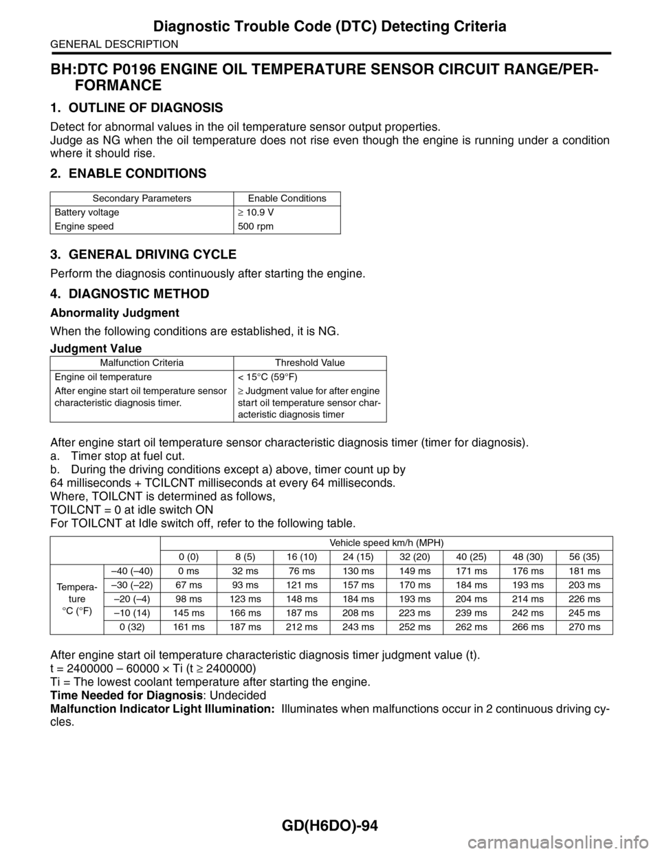
4. DIAGNOSTIC METHOD
Abnormality Judgment
When the following conditions are established, it is NG.
After engine start oil temperature sensor characteristic diagnosis timer (timer for diagnosis).
a. Timer stop at fuel cut.
b. During the driving conditions except a) above, timer count up by
64 milliseconds + TCILCNT milliseconds at every 64 milliseconds.
Where, TOILCNT is determined as follows,
TOILCNT = 0 at idle switch ON
For TOILCNT at Idle switch off, refer to the following table.
After engine start oil temperature characteristic diagnosis timer judgment value (t).
t = 2400000 – 60000 × Ti (t ≥ 2400000)
Ti = The lowest coolant temperature after starting the engine.
Time Needed for Diagnosis: Undecided
Malfunction Indicator Light Illumination: Illuminates when malfunctions occur in 2 continuous driving cy-
cles.
Secondary Parameters Enable Conditions
Battery voltage≥ 10.9 V
Engine speed 500 rpm
Judgment Value
Malfunction Criteria Threshold Value
Engine oil temperature < 15°C (59°F)
After engine start oil temperature sensor
characteristic diagnosis timer.
≥ Judgment value for after engine
start oil temperature sensor char-
acteristic diagnosis timer
Vehicle speed km/h (MPH)
0 (0) 8 (5) 16 (10) 24 (15) 32 (20) 40 (25) 48 (30) 56 (35)
Te m p e r a -
ture
°C (°F)
–40 (–40) 0 ms 32 ms 76 ms 130 ms 149 ms 171 ms 176 ms 181 ms
–30 (–22) 67 ms 93 ms 121 ms 157 ms 170 ms 184 ms 193 ms 203 ms
–20 (–4) 98 ms 123 ms 148 ms 184 ms 193 ms 204 ms 214 ms 226 ms
–10 (14) 145 ms 166 ms 187 ms 208 ms 223 ms 239 ms 242 ms 245 ms
0 (32) 161 ms 187 ms 212 ms 243 ms 252 ms 262 ms 266 ms 270 ms
Page 1744 of 2453
GD(H6DO)-132
Diagnostic Trouble Code (DTC) Detecting Criteria
GENERAL DESCRIPTION
Leak Diagnosis
DTC
P0442 Evaporative Emission Control System Leak Detected (Small Leak)
P0457 Evaporative Emission Control System Leak Detected (Fuel Cap Loose/Off)
Diagnostic method
The diagnostic method consists of creating a sealed vacuum in the fuel tank and then determining the pres-
ence of leakage from the speed at which the tank internal pressure returns to atmospheric pressure.
Mode A: (Estimated evaporation gas amount)
Calculate the tank pressure change amount (P1) when using mode A. After calculating P1, switch to mode B.
Mode B: (Negative pressure sealed)
Introduce negative pressure in the intake manifold to the tank.
Approx. 0 → –1.4 (0 → –10.5, 0 → –0.41) kPa (mmHg, inHg)
When the pressure above (desired negative pressure) is reached, enters Mode C.
In this case, if the tank pressure does not become the desired negative pressure, judge that there is a large
leakage (10 seconds or 25 seconds) in the system.
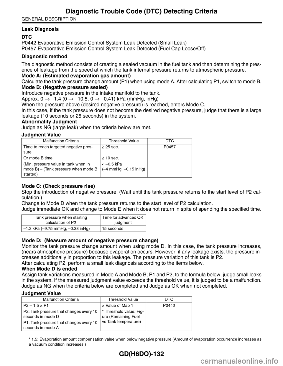
Abnormality Judgment
Judge as NG (large leak) when the criteria below are met.
Mode C: (Check pressure rise)
Stop the introduction of negative pressure. (Wait until the tank pressure returns to the start level of P2 cal-
culation.)
Change to Mode D when the tank pressure returns to the start level of P2 calculation.
Judge immediate OK and change to Mode E when it does not return in spite of spending the specified time.
Mode D: (Measure amount of negative pressure change)
Monitor the tank pressure change amount when using mode D. In this case, the tank pressure increases,
(nears atmospheric pressure) because evaporation occurs. However, if any leakage exists, the pressure in-
creases additionally in proportion to this leakage. The pressure variation of this tank is P2.
After calculating P2, perform a small leak diagnosis according to the items below.
When Mode D is ended
Assign tank variations measured in Mode A and Mode B; P1 and P2, to the formula below, judge small leaks
in the system. If the measured judgment value exceeds the threshold value, it is judged to be a malfunction.
Judge as NG when the criteria below are completed and Judge as OK when not completed.
* 1.5: Evaporation amount compensation value when below negative pressure (Amount of evaporation occurrence increases as
a vacuum condition increases.)
Judgment Value
Malfunction Criteria Threshold Value DTC
Time to reach targeted negative pres-
sure
≥ 25 sec. P0457
Or mode B time≥ 10 sec.
(Min. pressure value in tank when in
mode B) – (Tank pressure when mode B
started)
< –0.5 kPa
(–4 mmHg, –0.15 inHg)
Ta n k p r e s s u r e w h e n s t a r t i n g
calculation of P2
Time for advanced OK
judgment
–1.3 kPa (–9.75 mmHg, –0.38 inHg) 15 seconds
Judgment Value
Malfunction Criteria Threshold Value DTC
P2 – 1.5 × P1 > Value of Map 1 P0442
P2: Tank pressure that changes every 10
seconds in mode D
* Threshold value: Fig-
ure (Remaining Fuel
vs Tank temperature)
P1: Tank pressure that changes every 10
seconds in mode A