2009 SUBARU TRIBECA stop start
[x] Cancel search: stop startPage 1745 of 2453
GD(H6DO)-133
Diagnostic Trouble Code (DTC) Detecting Criteria
GENERAL DESCRIPTION
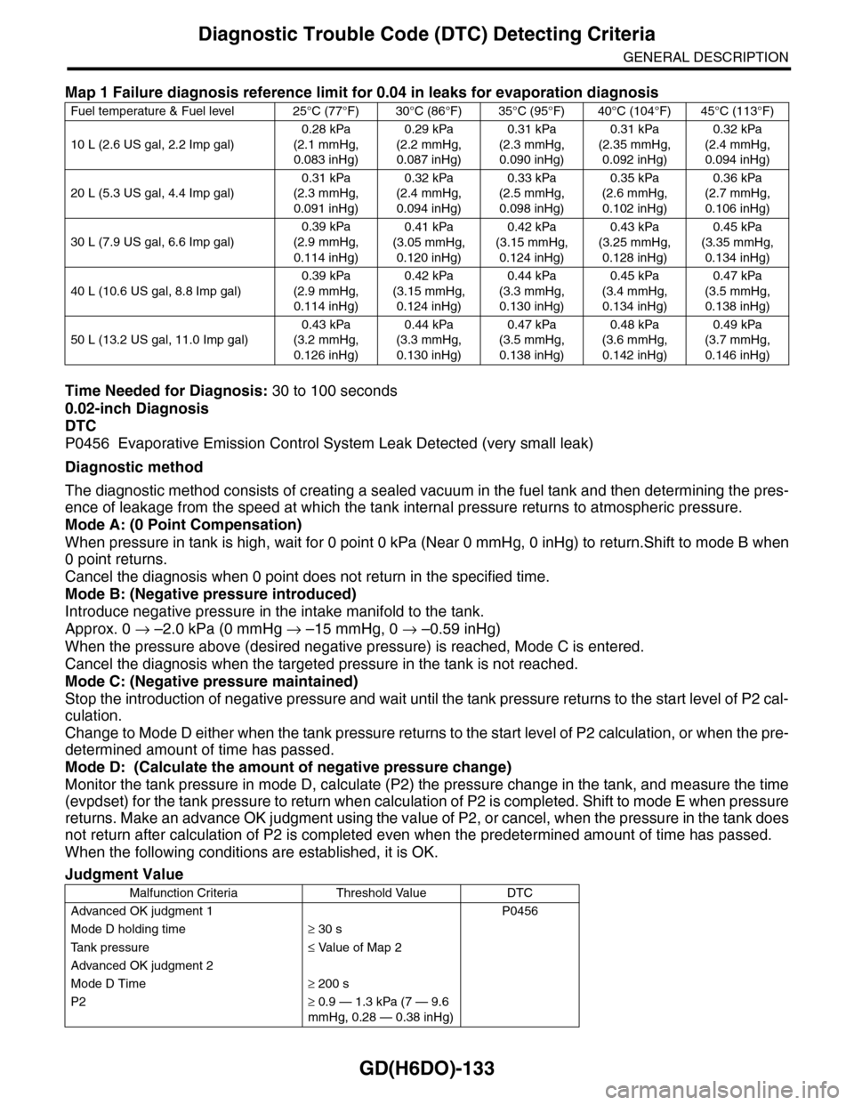
Time Needed for Diagnosis: 30 to 100 seconds
0.02-inch Diagnosis
DTC
P0456 Evaporative Emission Control System Leak Detected (very small leak)
Diagnostic method
The diagnostic method consists of creating a sealed vacuum in the fuel tank and then determining the pres-
ence of leakage from the speed at which the tank internal pressure returns to atmospheric pressure.
Mode A: (0 Point Compensation)
When pressure in tank is high, wait for 0 point 0 kPa (Near 0 mmHg, 0 inHg) to return.Shift to mode B when
0 point returns.
Cancel the diagnosis when 0 point does not return in the specified time.
Mode B: (Negative pressure introduced)
Introduce negative pressure in the intake manifold to the tank.
Approx. 0 → –2.0 kPa (0 mmHg → –15 mmHg, 0 → –0.59 inHg)
When the pressure above (desired negative pressure) is reached, Mode C is entered.
Cancel the diagnosis when the targeted pressure in the tank is not reached.
Mode C: (Negative pressure maintained)
Stop the introduction of negative pressure and wait until the tank pressure returns to the start level of P2 cal-
culation.
Change to Mode D either when the tank pressure returns to the start level of P2 calculation, or when the pre-
determined amount of time has passed.
Mode D: (Calculate the amount of negative pressure change)
Monitor the tank pressure in mode D, calculate (P2) the pressure change in the tank, and measure the time
(evpdset) for the tank pressure to return when calculation of P2 is completed. Shift to mode E when pressure
returns. Make an advance OK judgment using the value of P2, or cancel, when the pressure in the tank does
not return after calculation of P2 is completed even when the predetermined amount of time has passed.
When the following conditions are established, it is OK.
Map 1 Failure diagnosis reference limit for 0.04 in leaks for evaporation diagnosis
Fuel temperature & Fuel level 25°C (77°F) 30°C (86°F) 35°C (95°F) 40°C (104°F) 45°C (113°F)
10 L (2.6 US gal, 2.2 Imp gal)
0.28 kPa
(2.1 mmHg,
0.083 inHg)
0.29 kPa
(2.2 mmHg,
0.087 inHg)
0.31 kPa
(2.3 mmHg,
0.090 inHg)
0.31 kPa
(2.35 mmHg,
0.092 inHg)
0.32 kPa
(2.4 mmHg,
0.094 inHg)
20 L (5.3 US gal, 4.4 Imp gal)
0.31 kPa
(2.3 mmHg,
0.091 inHg)
0.32 kPa
(2.4 mmHg,
0.094 inHg)
0.33 kPa
(2.5 mmHg,
0.098 inHg)
0.35 kPa
(2.6 mmHg,
0.102 inHg)
0.36 kPa
(2.7 mmHg,
0.106 inHg)
30 L (7.9 US gal, 6.6 Imp gal)
0.39 kPa
(2.9 mmHg,
0.114 inHg)
0.41 kPa
(3.05 mmHg,
0.120 inHg)
0.42 kPa
(3.15 mmHg,
0.124 inHg)
0.43 kPa
(3.25 mmHg,
0.128 inHg)
0.45 kPa
(3.35 mmHg,
0.134 inHg)
40 L (10.6 US gal, 8.8 Imp gal)
0.39 kPa
(2.9 mmHg,
0.114 inHg)
0.42 kPa
(3.15 mmHg,
0.124 inHg)
0.44 kPa
(3.3 mmHg,
0.130 inHg)
0.45 kPa
(3.4 mmHg,
0.134 inHg)
0.47 kPa
(3.5 mmHg,
0.138 inHg)
50 L (13.2 US gal, 11.0 Imp gal)
0.43 kPa
(3.2 mmHg,
0.126 inHg)
0.44 kPa
(3.3 mmHg,
0.130 inHg)
0.47 kPa
(3.5 mmHg,
0.138 inHg)
0.48 kPa
(3.6 mmHg,
0.142 inHg)
0.49 kPa
(3.7 mmHg,
0.146 inHg)
Judgment Value
Malfunction Criteria Threshold Value DTC
Advanced OK judgment 1 P0456
Mode D holding time≥ 30 s
Ta n k p r e s s u r e≤ Value of Map 2
Advanced OK judgment 2
Mode D Time≥ 200 s
P2≥ 0.9 — 1.3 kPa (7 — 9.6
mmHg, 0.28 — 0.38 inHg)
Page 1856 of 2453
LU(H6DO)-7
Engine Oil
LUBRICATION
3. Engine Oil
A: INSPECTION
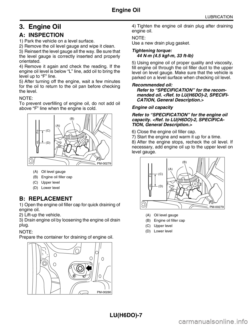
1) Park the vehicle on a level surface.
2) Remove the oil level gauge and wipe it clean.
3) Reinsert the level gauge all the way. Be sure that
the level gauge is correctly inserted and properly
orientated.
4) Remove it again and check the reading. If the
engine oil level is below “L” line, add oil to bring the
level up to “F” line.
5) After turning off the engine, wait a few minutes
for the oil to return to the oil pan before checking
the level.
NOTE:
To prevent overfilling of engine oil, do not add oil
above “F” line when the engine is cold.
B: REPLACEMENT
1) Open the engine oil filler cap for quick draining of
engine oil.
2) Lift-up the vehicle.
3) Drain engine oil by loosening the engine oil drain
plug.
NOTE:
Prepare the container for draining of engine oil.
4) Tighten the engine oil drain plug after draining
engine oil.
NOTE:
Use a new drain plug gasket.
Tightening torque:
44 N·m (4.5 kgf-m, 33 ft-lb)
5) Using engine oil of proper quality and viscosity,
fill engine oil through the oil filler duct to the upper
level on level gauge. Make sure that the vehicle is
parked on a level surface when checking oil level.
Recommended oil:
Refer to “SPECIFICATION” for the recom-
mended oil.
Engine oil capacity
Refer to “SPECIFICATION” for the engine oil
capacity.
6) Close the engine oil filler cap.
7) Start the engine and warm it up for a time.
8) After the engine stops, recheck the oil level. If
necessary, add engine oil up to the upper level on
level gauge.
(A) Oil level gauge
(B) Engine oil filler cap
(C) Upper level
(D) Lower level
PM-00279
(A)
(B)
(C)
(D)
PM-00280
(A) Oil level gauge
(B) Engine oil filler cap
(C) Upper level
(D) Lower level
PM-00279
(A)
(B)
(C)
(D)
Page 1888 of 2453
ME(H6DO)-22
Idle Speed
MECHANICAL
3. Idle Speed
A: INSPECTION
1) Before checking the idle speed, check the fol-
lowing item:
(1) Check the air cleaner element is free from
clogging, ignition timing is correct, spark plugs
are in good condition, and hoses are connected
properly.
(2) Check the malfunction indicator light does
not illuminate.
2) Idle the engine.
3) Stop the engine, and turn the ignition switch to
OFF.
4) Insert the cartridge to Subaru Select Monitor.
5) Connect the Subaru Select Monitor to data link
connector.
6) Turn the ignition switch to ON and Subaru Select
Monitor switch to ON.
7) Select {Each System Check} in Main Menu.
8) Select {Engine} in Selection Menu.
9) Select {Current Data Display & Save} in Engine
Control System Diagnosis.
10) Select {Data Display} in Data Display Menu.
11) Start the engine, and read the engine idle
speed.
12) Check the idle speed when no-loaded. (Head-
light, heater fan, rear defroster, radiator fan, A/C
and etc. are OFF)
Idle speed [No load and gears in neutral]:
650±50 rpm
13) Check the idle speed when loaded. (Turn the A/
C switch to “ON” and operate the compressor for at
least one minute before measurement.)
Idle speed [A/C ON and gears in neutral]:
770±50 rpm
NOTE:
Idle speed cannot be adjusted manually, because
the idle speed is automatically adjusted. If the pre-
scribed idle speed cannot be maintained, refer to
General On-board Diagnosis Table under “Engine
Control System”.
Page 1889 of 2453
ME(H6DO)-23
Ignition Timing
MECHANICAL
4. Ignition Timing
A: INSPECTION
CAUTION:
After warming-up, engine becomes very hot. Be
careful not to burn yourself at measurement.
1) Before checking the ignition timing, check the
following item:
(1) Check the air cleaner element is free from
clogging, spark plugs are in good condition, and
hoses are connected properly.
(2) Check the malfunction indicator light does
not illuminate.
2) Idle the engine.
3) Stop the engine, and turn the ignition switch to
OFF.
4) Insert the cartridge to Subaru Select Monitor.
5) Connect the Subaru Select Monitor to data link
connector.
6) Turn the ignition switch to ON and Subaru Select
Monitor switch to ON.
7) Select {Each System Check} in Main Menu.
8) Select {Engine} in Selection Menu.
9) Select {Current Data Display & Save} in Engine
Control System Diagnosis.
10) Select {Data Display} in Data Display Menu.
11) Start the engine and check the ignition timing at
idle speed.
Ignition timing [BTDC/rpm]:
15°±8°/650
If the timing is not correct, check the ignition control
system. Refer to Engine Control System.
Page 1901 of 2453
ME(H6DO)-35
Engine Assembly
MECHANICAL
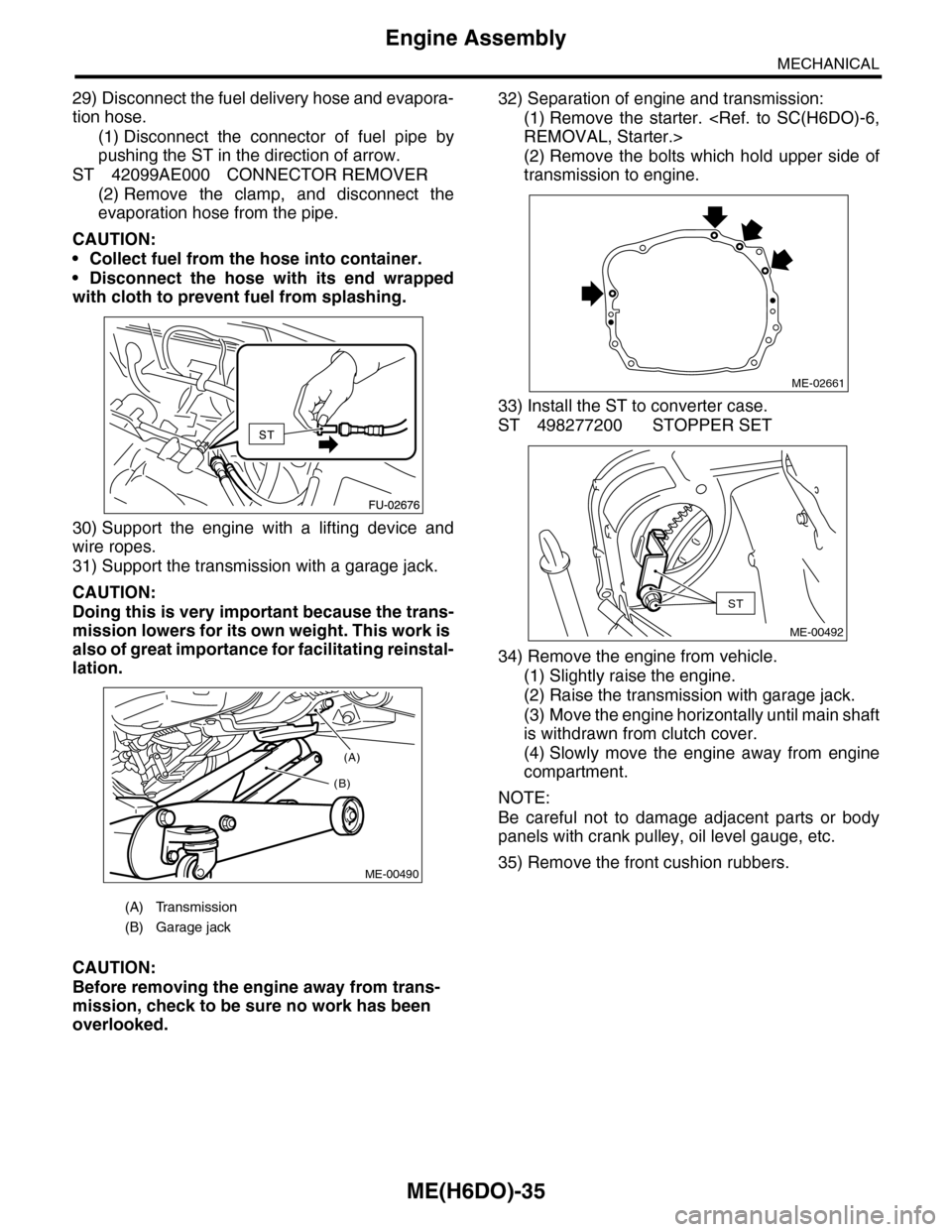
29) Disconnect the fuel delivery hose and evapora-
tion hose.
(1) Disconnect the connector of fuel pipe by
pushing the ST in the direction of arrow.
ST 42099AE000 CONNECTOR REMOVER
(2) Remove the clamp, and disconnect the
evaporation hose from the pipe.
CAUTION:
•Collect fuel from the hose into container.
•Disconnect the hose with its end wrapped
with cloth to prevent fuel from splashing.
30) Support the engine with a lifting device and
wire ropes.
31) Support the transmission with a garage jack.
CAUTION:
Doing this is very important because the trans-
mission lowers for its own weight. This work is
also of great importance for facilitating reinstal-
lation.
CAUTION:
Before removing the engine away from trans-
mission, check to be sure no work has been
overlooked.
32) Separation of engine and transmission:
(1) Remove the starter.
(2) Remove the bolts which hold upper side of
transmission to engine.
33) Install the ST to converter case.
ST 498277200 STOPPER SET
34) Remove the engine from vehicle.
(1) Slightly raise the engine.
(2) Raise the transmission with garage jack.
(3) Move the engine horizontally until main shaft
is withdrawn from clutch cover.
(4) Slowly move the engine away from engine
compartment.
NOTE:
Be careful not to damage adjacent parts or body
panels with crank pulley, oil level gauge, etc.
35) Remove the front cushion rubbers.
(A) Transmission
(B) Garage jack
(A)
(B)
ME-00490
ME-02661
ST
ME-00492
Page 1902 of 2453
ME(H6DO)-36
Engine Assembly
MECHANICAL
B: INSTALLATION
1) Install the front cushion rubbers.
Tightening torque:
35 N·m (3.6 kgf-m, 25.8 ft-lb)
2) Position the engine in engine compartment and
align it with transmission.
NOTE:
Be careful not to damage adjacent parts or body
panels with crank pulley, oil level gauge, etc.
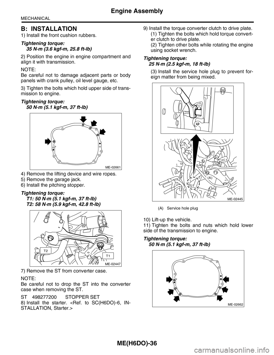
3) Tighten the bolts which hold upper side of trans-
mission to engine.
Tightening torque:
50 N·m (5.1 kgf-m, 37 ft-lb)
4) Remove the lifting device and wire ropes.
5) Remove the garage jack.
6) Install the pitching stopper.
Tightening torque:
T1: 50 N·m (5.1 kgf-m, 37 ft-lb)
T2: 58 N·m (5.9 kgf-m, 42.8 ft-lb)
7) Remove the ST from converter case.
NOTE:
Be careful not to drop the ST into the converter
case when removing the ST.
ST 498277200 STOPPER SET
8) Install the starter.
9) Install the torque converter clutch to drive plate.
(1) Tighten the bolts which hold torque convert-
er clutch to drive plate.
(2) Tighten other bolts while rotating the engine
using socket wrench.
Tightening torque:
25 N·m (2.5 kgf-m, 18 ft-lb)
(3) Install the service hole plug to prevent for-
eign matter from being mixed.
10) Lift-up the vehicle.
11) Tighten the bolts and nuts which hold lower
side of the transmission to engine.
Tightening torque:
50 N·m (5.1 kgf-m, 37 ft-lb)
ME-02661
T2
T1
ME-02447
(A) Service hole plug
(A)
ME-02445
ME-02662
Page 1961 of 2453
SC(H6DO)-3
General Description
STARTING/CHARGING SYSTEMS
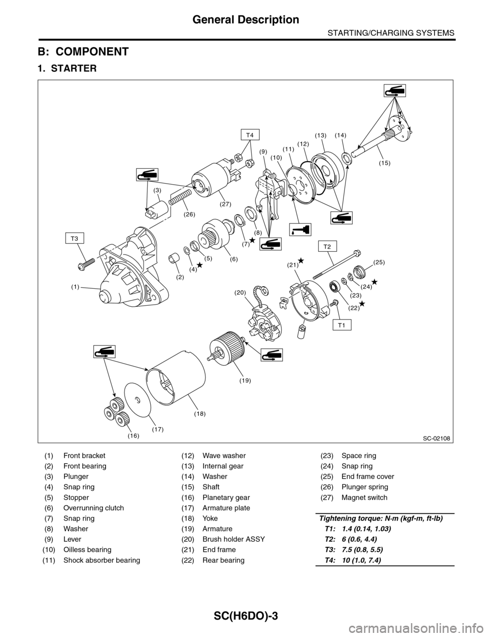
B: COMPONENT
1. STARTER
(1) Front bracket (12) Wave washer (23) Space ring
(2) Front bearing (13) Internal gear (24) Snap ring
(3) Plunger (14) Washer (25) End frame cover
(4) Snap ring (15) Shaft (26) Plunger spring
(5) Stopper (16) Planetary gear (27) Magnet switch
(6) Overrunning clutch (17) Armature plate
(7) Snap ring (18) YokeTightening torque: N·m (kgf-m, ft-lb)
(8) Washer (19) ArmatureT1: 1.4 (0.14, 1.03)
(9) Lever (20) Brush holder ASSYT2: 6 (0.6, 4.4)
(10) Oilless bearing (21) End frameT3: 7.5 (0.8, 5.5)
(11) Shock absorber bearing (22) Rear bearingT4: 10 (1.0, 7.4)
SC-02108
T3
T1
T2
(1)
(2)
T4
(4)(21)
(22)
(23)
(24)
(25)(5)(6)
(7)
(8)
(15)
(14)(13)
(12)(11)
(10)(9)
(3)
(26)
(27)
(16)(17)
(18)
(19)
(20)
Page 1966 of 2453
SC(H6DO)-8
Starter
STARTING/CHARGING SYSTEMS
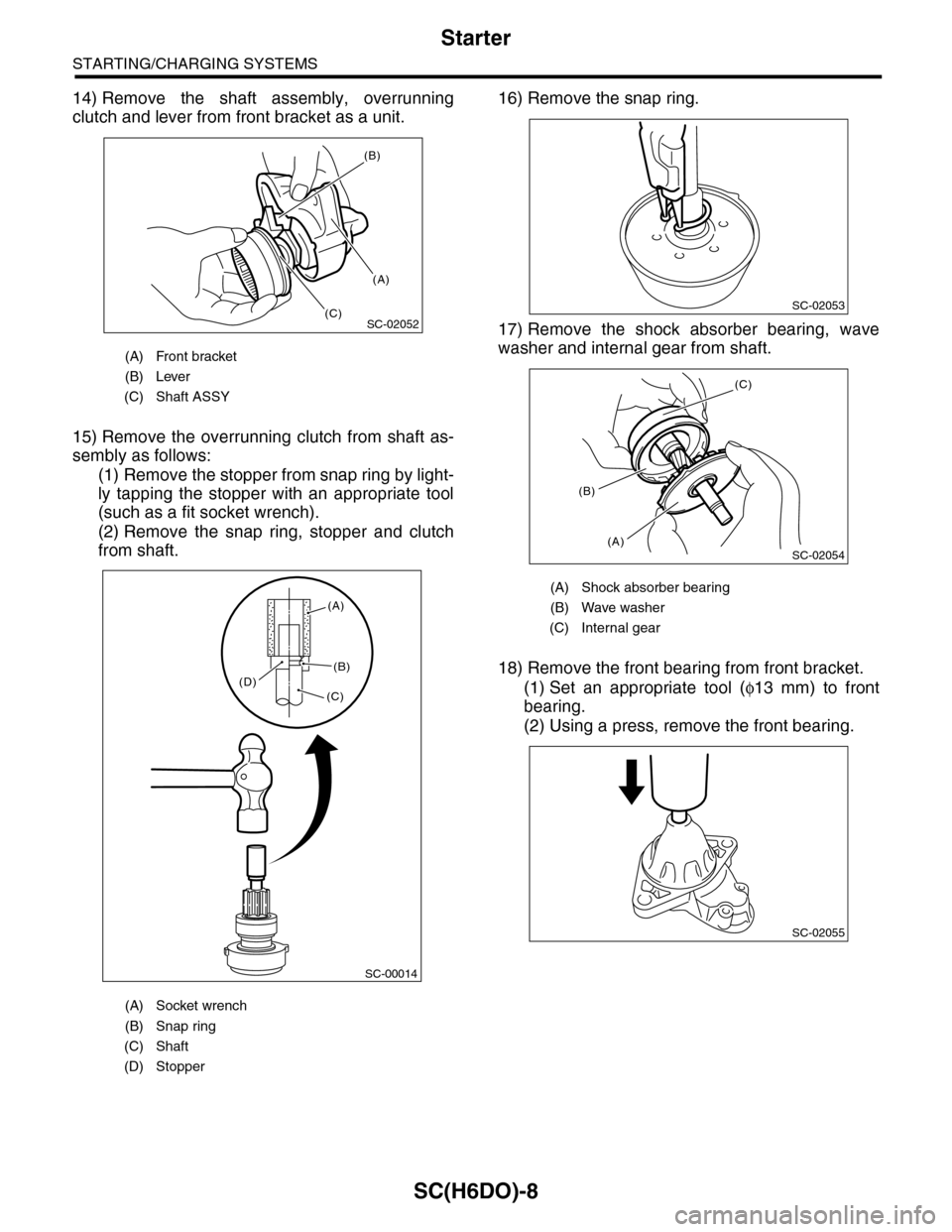
14) Remove the shaft assembly, overrunning
clutch and lever from front bracket as a unit.
15) Remove the overrunning clutch from shaft as-
sembly as follows:
(1) Remove the stopper from snap ring by light-
ly tapping the stopper with an appropriate tool
(such as a fit socket wrench).
(2) Remove the snap ring, stopper and clutch
from shaft.
16) Remove the snap ring.
17) Remove the shock absorber bearing, wave
washer and internal gear from shaft.
18) Remove the front bearing from front bracket.
(1) Set an appropriate tool (φ13 mm) to front
bearing.
(2) Using a press, remove the front bearing.
(A) Front bracket
(B) Lever
(C) Shaft ASSY
(A) Socket wrench
(B) Snap ring
(C) Shaft
(D) Stopper
SC-02052
(B)
(A)
(C)
SC-00014
(A)
(B)
(C)(D)
(A) Shock absorber bearing
(B) Wave washer
(C) Internal gear
SC-02053
SC-02054
(C)
(A)
(B)
SC-02055