Page 49 of 2453

AB(diag)-25
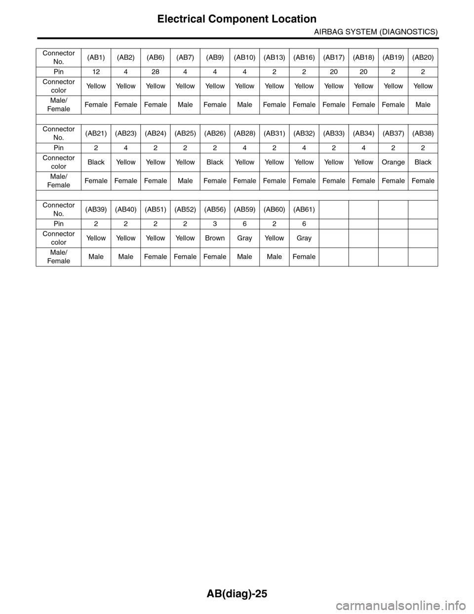
Electrical Component Location
AIRBAG SYSTEM (DIAGNOSTICS)
Connector
No.(AB1) (AB2) (AB6) (AB7) (AB9) (AB10) (AB13) (AB16) (AB17) (AB18) (AB19) (AB20)
Pin 12 4 28 4 4 4 2 2 20 20 2 2
Connector
colorYe l l o w Ye l l o w Ye l l o w Ye l l o w Ye l l o w Ye l l o w Ye l l o w Ye l l o w Ye l l o w Ye l l o w Ye l l o w Ye l l o w
Male/
FemaleFemale Female Female Male Female Male Female Female Female Female Female Male
Connector
No.(AB21) (AB23) (AB24) (AB25) (AB26) (AB28) (AB31) (AB32) (AB33) (AB34) (AB37) (AB38)
Pin 2 4 2 2 2 4 2 4 2 4 2 2
Connector
colorBlack Yellow Yellow Yellow Black Yellow Yellow Yellow Yellow Yellow Orange Black
Male/
FemaleFemale Female Female Male Female Female Female Female Female Female Female Female
Connector
No.(AB39) (AB40) (AB51) (AB52) (AB56) (AB59) (AB60) (AB61)
Pin 2 2 2 2 3 6 2 6
Connector
colorYe l l o w Ye l l o w Ye l l o w Ye l l o w B r o w n G r a y Ye l l o w G r a y
Male/
FemaleMale Male Female Female Female Male Male Female
Page 50 of 2453

AB(diag)-26
Airbag Connector
AIRBAG SYSTEM (DIAGNOSTICS)
5. Airbag Connector
A: PROCEDURE
1. BUCKLE SWITCH
1) How to disconnect:
(1) Move the slide lock (A) in the direction of ar-
row.
(2) While holding the slide lock (A) in moved po-
sition, disconnect the connector.
CAUTION:
When pulling the slide lock or disconnecting
connector, be sure to hold the connector, not
the harness.
2) How to connect:
Holding the connector (A), and push it in carefully
until a clicking sound is heard.
CAUTION:
Be sure to insert the connector in until it is
locked. Then pull it gently to make sure that it is
locked.
2. DRIVER’S AIRBAG MODULE AND PRE-
TENSIONER
1) How to disconnect:
(1) Using a flat tip screwdriver, pry the push lock
upward to unlock.
(2) Pull and disconnect the connector from the
driver’s airbag module assembly or retractor as-
sembly.
2) How to connect:
Connect the connector in the reverse order of dis-
connecting. At this time, be sure to insert the push
lock until a clicking sound is heard.
CAUTION:
•Be sure to insert the connector in until it is
locked. Then pull it gently to make sure that it is
locked.
•Be sure to push the push lock in securely.
NOTE:
The connector cannot be connected when the push
lock is in lock position. To connect the connector,
set the push lock to unlock position.
AB-00721
(A)
AB-00016
AB-00478
AB-00479
AB-00480
Page 51 of 2453

AB(diag)-27
Airbag Connector
AIRBAG SYSTEM (DIAGNOSTICS)
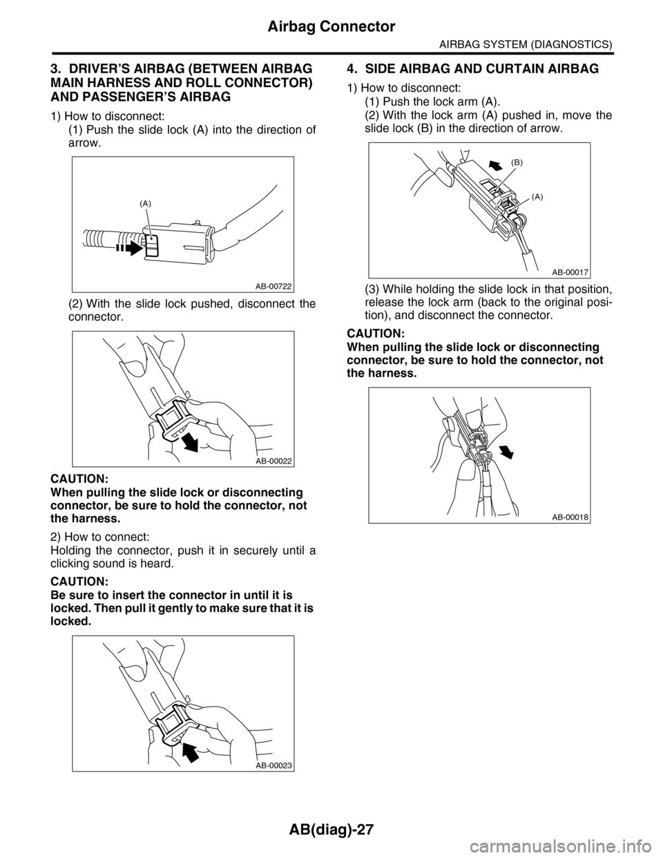
3. DRIVER’S AIRBAG (BETWEEN AIRBAG
MAIN HARNESS AND ROLL CONNECTOR)
AND PASSENGER’S AIRBAG
1) How to disconnect:
(1) Push the slide lock (A) into the direction of
arrow.
(2) With the slide lock pushed, disconnect the
connector.
CAUTION:
When pulling the slide lock or disconnecting
connector, be sure to hold the connector, not
the harness.
2) How to connect:
Holding the connector, push it in securely until a
clicking sound is heard.
CAUTION:
Be sure to insert the connector in until it is
locked. Then pull it gently to make sure that it is
locked.
4. SIDE AIRBAG AND CURTAIN AIRBAG
1) How to disconnect:
(1) Push the lock arm (A).
(2) With the lock arm (A) pushed in, move the
slide lock (B) in the direction of arrow.
(3) While holding the slide lock in that position,
release the lock arm (back to the original posi-
tion), and disconnect the connector.
CAUTION:
When pulling the slide lock or disconnecting
connector, be sure to hold the connector, not
the harness.
AB-00722
(A)
AB-00022
AB-00023
AB-00017
(A)
(B)
AB-00018
Page 52 of 2453
AB(diag)-28
Airbag Connector
AIRBAG SYSTEM (DIAGNOSTICS)
5. FRONT SUB SENSOR, SIDE AIRBAG
SENSOR, CURTAIN AIRBAG SENSOR AND
SEAT POSITION SENSOR LH
1) How to disconnect:
Holding outer part (A), pull it in the direction of ar-
row.
CAUTION:
When pulling the slide lock or disconnecting
connector, be sure to hold the connector, not
the harness.
2) How to connect:
Holding the connector, push it in securely until a
clicking sound is heard.
CAUTION:
•Outer side (A) move back, and so do not put
your hand on the outer part.
•Be sure to insert the connector in until it is
locked. Then pull it gently to make sure that it is
locked.
AB-00024
AB-00025
Page 53 of 2453

AB(diag)-29
Airbag Control Module I/O Signal
AIRBAG SYSTEM (DIAGNOSTICS)
6. Airbag Control Module I/O Signal
A: ELECTRICAL SPECIFICATION
•Terminal numbers in airbag control module connector are shown in the figure.
•Airbag warning light illuminates when the connector is removed from airbag control module.
Item Control module terminal No.
Line end check connector(1)-2
Diagnosis connector(1)-19
Data link connector(1)-12
Combination meter(1)-3
Battery power supply Common use fuse (1)-6
Dedicated fuse (1)-5
Passenger’s airbag module level one + (1)-10
–(1)-11
Passenger’s airbag module level two + (1)-8
–(1)-7
Driver’s airbag module level one + (1)-14
–(1)-13
Driver’s airbag module level two + (1)-16
–(1)-17
Fr o nt su b se ns or L H Powe r su p pl y a n d co mmu-
nication(1)-15
GND (1)-26
Fr o nt su b se ns or RH Powe r su p pl y a n d co mmu-
nication(1)-9
GND (1)-20
Ground line (GND)(1)-27
(1)-28
Passenger’s airbag OFF indicator (1)-1
Passenger’s airbag ON indicator (1)-18
Passenger’s seat belt war ning light (integrated module) (1)-24
Seat belt buckle switch LH + (2)-19
–(2)-2
Seat position sensor LH + (2)-3
–(2)-4
AB-00937
123456789101112
1314151617181920
123456789101112
1314151617181920
1234567891011121314151617
1819202122232425262728
(1)(2) (3)
Page 55 of 2453

AB(diag)-31
Subaru Select Monitor
AIRBAG SYSTEM (DIAGNOSTICS)
7. Subaru Select Monitor
A: OPERATION
1. READ DIAGNOSTIC TROUBLE CODE
(DTC)
When malfunction of airbag system occurs, the
DTC stored in airbag control module will be read
out.
1) Prepare the Subaru Select Monitor kit.
AB(diag)-8, SPECIAL TOOL, PREPARATION
TOOL, General Description.>
2) Connect the diagnosis cable to Subaru Select
Monitor.
3) Insert the cartridge to Subaru Select Monitor.
TION TOOL, General Description.>
4) Connect the Subaru Select Monitor to data link
connector.
(1) Data link connector (1) is located in the low-
er portion of instrument panel (on the driver’s
side).
(2) Connect the diagnosis cable to data link
connector.
CAUTION:
Do not connect the scan tools except for Suba-
ru Select Monitor.
5) Turn the ignition switch to ON (engine OFF) and
turn the Subaru Select Monitor switch to ON.
6) On the «Main Menu» display screen, select the
{Each System Check} and press the [YES] key.
7) On the «System Selection Menu» display
screen, select the {Airbag System} and press the
[YES] key.
8) {Press the [YES] key after the {**MY AIRBAG
SYSTEM} is displayed.
9) On the «Airbag System» screen, select the
{DTC Display}, and then press the [YES] key.
NOTE:
•For details concerning operation procedure, re-
fer to the “SUBARU SELECT MONITOR OPERA-
TION MANUAL”.
•For details concerning DTCs, refer to List of Di-
agnostic Trouble Code (DTC).
45, List of Diagnostic Trouble Code (DTC).>
ABS00111
ABS00112
EN-03693
(1) Power switch
ABS00114
(1)
Page 57 of 2453
AB(diag)-33
Subaru Select Monitor
AIRBAG SYSTEM (DIAGNOSTICS)
B: INSPECTION
1. COMMUNICATION FOR INITIALIZING IMPOSSIBLE
DETECTING CONDITION:
Defective harness connector
TROUBLE SYMPTOM:
Communication is impossible between the airbag control module and the Subaru Select Monitor.
WIRING DIAGRAM:
AB-01299
AB1B40
12345678
910 11 12 13 14 15 16
MAIN SBF
SBF-6
NO.12NO.25
B40
AB6
B31
AB1
E
EE
1
10
12
7
282765
NO.13
IGNITIONSWITCH
AIRBAG CONTROL MODULE
BATTERY
DATA LINK CONNECTOR
123456789101112
AB6
1234567891011121314161715
1819202122232425262728
910
Page 58 of 2453

AB(diag)-34
Subaru Select Monitor
AIRBAG SYSTEM (DIAGNOSTICS)
Step Check Yes No
1CHECK IGNITION SWITCH.Is the ignition switch ON? Go to step 2.Turn the ignition
switch to ON, and
select the airbag
mode using the
Subaru Select
Monitor.
2CHECK BATTERY.
1) Turn the ignition switch to OFF.
2) Measure the battery voltage.
Is the voltage more than 11 V? Go to step 3.Charge or replace
the battery.
3CHECK BATTERY TERMINAL.Is there poor contact at battery
terminal?
Repair or tighten
the battery termi-
nal.
Go to step 4.
4CHECK SUBARU SELECT MONITOR COM-
MUNICATION.
1) Turn the ignition switch to ON.
2) Using the Subaru Select Monitor, check
whether communication to other system can
be executed normally.
Are the system name and
model year displayed on Sub-
aru Select Monitor?
Go to step 9.Go to step 5.
5CHECK AIRBAG CONTROL MODULE CON-
NECTOR.
1) Turn the ignition switch to OFF, disconnect
the battery ground cable, and wait more than
20 seconds.
2) Is the connector of the air bag control mod-
ule (AB6) securely connected?
Is the connector of the air bag
control module securely con-
nected?
Go to step 6.Connect the con-
nector of the air-
bag control
module.
6CHECK SUBARU SELECT MONITOR COM-
MUNICATION.
1) Turn the ignition switch to OFF.
2) Disconnect the airbag control module con-
nector.
3) Turn the ignition switch to ON.
4) Check whether communication to other
systems can be executed normally.
Are the system name and
model year displayed on Sub-
aru Select Monitor?
Replace the airbag
control module.
Airbag Control
Module.>
Go to step 7.
7CHECK HARNESS CONNECTOR BETWEEN
EACH CONTROL MODULE AND DATA LINK
CONNECTOR.
1) Turn the ignition switch to OFF.
2) Disconnect the airbag control module,
ABSCM&H/U, ECM and TCM.
3) Measure the resistance between data link
connector and chassis ground.
Connector & terminal
(B40) No. 10 — Chassis ground:
Is the resistance more than 1
MΩ?
Go to step 8.Repair the har-
ness and connec-
tor between each
control module
and data link con-
nector. (Replace
the harness with-
out repairing the
airbag harness.)
8CHECK THE OUTPUT SIGNAL TO THE AIR-
BAG CONTROL MODULE.
1) Turn the ignition switch to ON in the status
of step 7.
2) Measure the voltage between data link con-
nector and chassis ground.
Connector & terminal
(B40) No. 10 (+) — Chassis ground (–):
Is the voltage less than 1 V? Go to step 9.Repair the har-
ness and connec-
tor between each
control module
and data link con-
nector. (Replace
the harness with-
out repairing the
airbag harness.)