Page 1112 of 2453

WT-6
Tire
WHEEL AND TIRE SYSTEM
2. Tire
A: INSPECTION
1) Take stones, glass, nails etc. out of the tread
groove.
2) Replace tires in the following cases.
CAUTION:
•When replacing a tire, make sure to use only
tires of the same size, construction and load
range as originally installed.
•Use a tire changer when removing the tire
from the wheel.
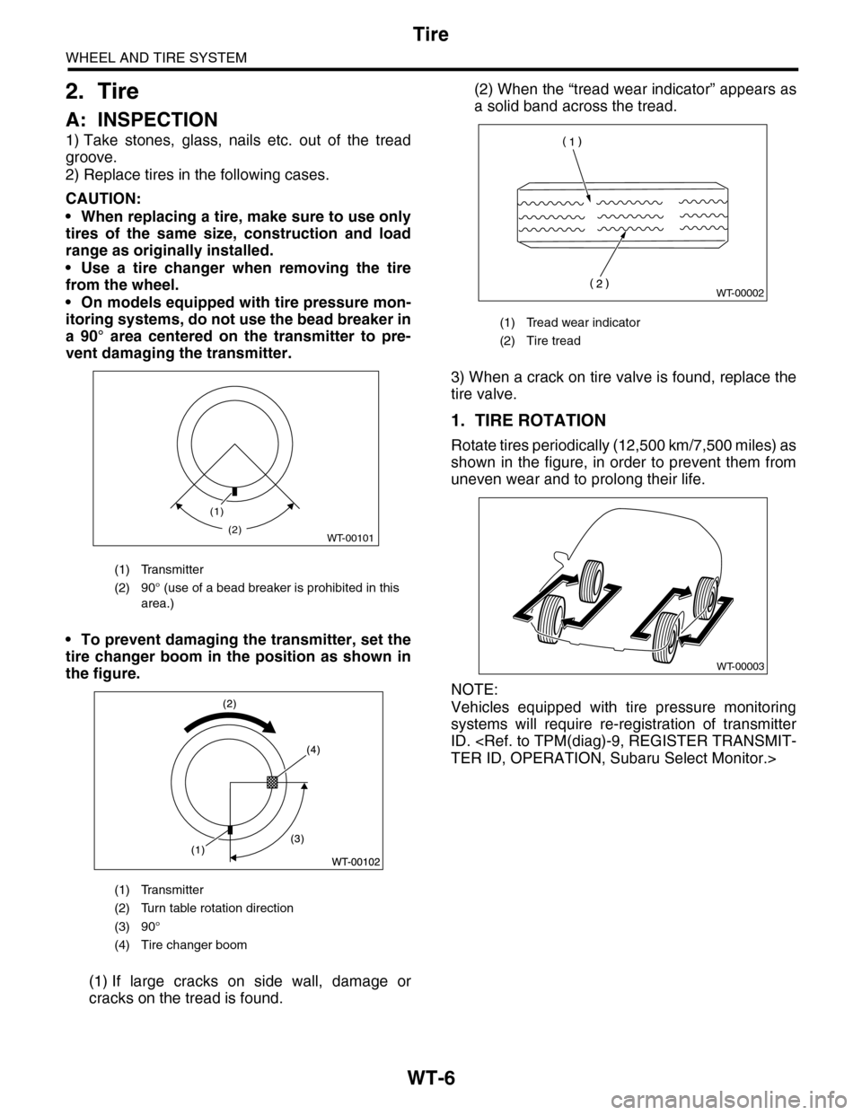
•On models equipped with tire pressure mon-
itoring systems, do not use the bead breaker in
a 90° area centered on the transmitter to pre-
vent damaging the transmitter.
•To prevent damaging the transmitter, set the
tire changer boom in the position as shown in
the figure.
(1) If large cracks on side wall, damage or
cracks on the tread is found.
(2) When the “tread wear indicator” appears as
a solid band across the tread.
3) When a crack on tire valve is found, replace the
tire valve.
1. TIRE ROTATION
Rotate tires periodically (12,500 km/7,500 miles) as
shown in the figure, in order to prevent them from
uneven wear and to prolong their life.
NOTE:
Vehicles equipped with tire pressure monitoring
systems will require re-registration of transmitter
ID.
TER ID, OPERATION, Subaru Select Monitor.>
(1) Transmitter
(2) 90° (use of a bead breaker is prohibited in this
area.)
(1) Transmitter
(2) Turn table rotation direction
(3) 90°
(4) Tire changer boom
(1)
WT-00101(2)
(1) Tread wear indicator
(2) Tire tread
WT-00002
WT-00003
Page 1116 of 2453
WT-10
“T–type” Tire
WHEEL AND TIRE SYSTEM
5. “T–type” Tire
A: NOTE
“T–type” tire for temporary use is equipped as a
spare tire.
CAUTION:
•Do not drive at a speed greater than 100 km/h
(62 MPH).
•For the model with tire pressure monitoring
system, the indicator light may blink when run-
ning with the “T-type” tire.
B: REPLACEMENT
Refer to Aluminum Wheels for removal and instal-
lation procedures of the “T–type”.
REMOVAL, Aluminum Wheel.>
CAUTION:
The “T–type” tire is only for temporary use. Re-
place with a conventional tire as soon as possi-
ble.
C: INSPECTION
1) Check the tire air pressure.
Specifications:
420 kPa (4.2 kg/cm2, 60 psi)
2) Take stones, glass, nails, etc. out of the tread
groove.
3) Check the tires for deformation, cracks, partial
wear, or wear.
CAUTION:
Replace the tire with a new one if defective.
Page 1117 of 2453

WT-11
Tire Pressure Monitoring System
WHEEL AND TIRE SYSTEM
6. Tire Pressure Monitoring
System
A: REMOVAL
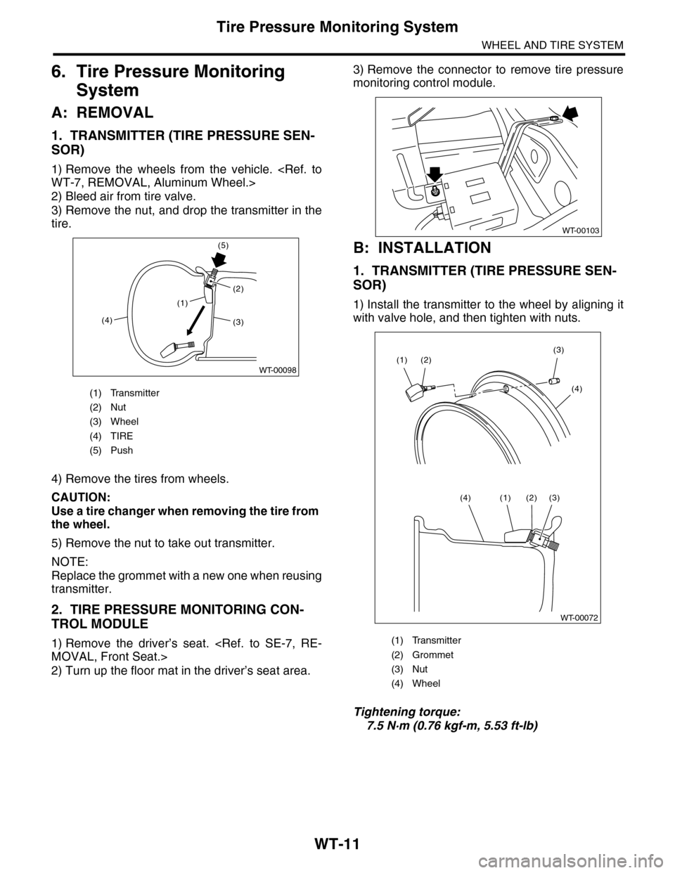
1. TRANSMITTER (TIRE PRESSURE SEN-
SOR)
1) Remove the wheels from the vehicle.
WT-7, REMOVAL, Aluminum Wheel.>
2) Bleed air from tire valve.
3) Remove the nut, and drop the transmitter in the
tire.
4) Remove the tires from wheels.
CAUTION:
Use a tire changer when removing the tire from
the wheel.
5) Remove the nut to take out transmitter.
NOTE:
Replace the grommet with a new one when reusing
transmitter.
2. TIRE PRESSURE MONITORING CON-
TROL MODULE
1) Remove the driver’s seat.
MOVAL, Front Seat.>
2) Turn up the floor mat in the driver’s seat area.
3) Remove the connector to remove tire pressure
monitoring control module.
B: INSTALLATION
1. TRANSMITTER (TIRE PRESSURE SEN-
SOR)
1) Install the transmitter to the wheel by aligning it
with valve hole, and then tighten with nuts.
Tightening torque:
7.5 N·m (0.76 kgf-m, 5.53 ft-lb)
(1) Transmitter
(2) Nut
(3) Wheel
(4) TIRE
(5) Push
(1)
(4)
(5)
(2)
WT-00098
(3)
(1) Transmitter
(2) Grommet
(3) Nut
(4) Wheel
WT-00103
WT-00072
(2)(3)
(4)
(1)
(3)(2)(1)(4)
Page 1118 of 2453
WT-12
Tire Pressure Monitoring System
WHEEL AND TIRE SYSTEM
2) Install the tires to wheels.
CAUTION:
•Use a tire changer when installing tire to
wheel.
•To prevent damaging the transmitter, set the
tire changer boom in the position as shown in
the figure.
3) Install the wheels to vehicle.
STALLATION, Aluminum Wheel.>
4) Register the transmitter ID to the tire pressure
monitoring control module.
REGISTER TRANSMITTER ID, OPERATION,
Subaru Select Monitor.>
2. TIRE PRESSURE MONITORING CON-
TROL MODULE
Install in the reverse order of removal.
Tightening torque:
8 N·m (0.8 kgf-m, 5.8 ft-lb)
C: ADJUSTMENT
Re-register the transmitter ID when transmitter has
been replaced or tires have been rotated.
TPM(diag)-9, REGISTER TRANSMITTER ID, OP-
ERATION, Subaru Select Monitor.>
(1) Transmitter
(2) Turn table rotation direction
(3) 90°
(4) Tire changer boom
Page 2006 of 2453

PM-23
Parking Brake
PERIODIC MAINTENANCE SERVICES
16.Parking Brake
A: INSPECTION
Inspect the brake linings and disc rotor of both
sides of the rear brake at the same time by remov-
ing disc rotor.
1) Inspect the brake shoes for damage or deforma-
tion and check the brake linings for wear.
NOTE:
Always replace both primary and secondary brake
shoes for the left and right wheels at the same time.
Thickness of brake lining (except for back metal):
Standard: 4.0 mm (0.157 in)
Wear limit: 1.5 mm (0.059 in)
2) Check the inside of disk rotor for wear, dents or
other damage. If the inside surface of dick rotor is
streaked, correct the surface with emery cloth
(#200 or more). If it is unevenly worn or tapered,
correct or replace it.
Brake drum inside diameter:
Standard: 210 mm (8.26 in)
Wear limit: 211 mm (8.30 in)
3) If the deformation or wear of back plate, shoe,
etc. is noticeable, replace them.
4) When the shoe return spring tension is exces-
sively weakened, replace it.
5) Check whether the parking brake pedal is at the
predetermined number of notches (5 to 6 notches).
B: ADJUSTMENT
1) Remove the rear tire and release the parking brake.
2) Remove the cover (rubber) installed on the disc rotor.
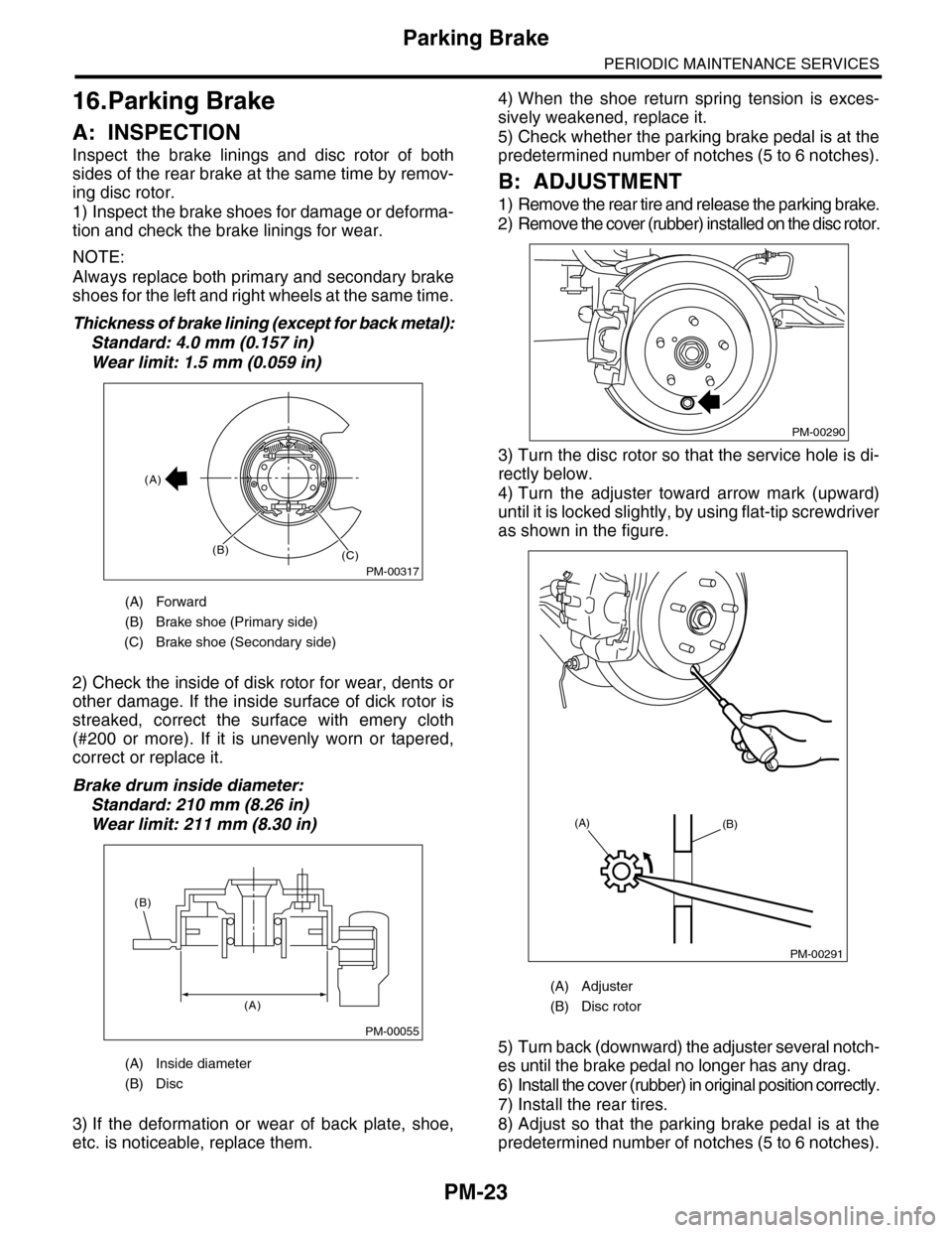
3) Turn the disc rotor so that the service hole is di-
rectly below.
4) Turn the adjuster toward arrow mark (upward)
until it is locked slightly, by using flat-tip screwdriver
as shown in the figure.
5) Turn back (downward) the adjuster several notch-
es until the brake pedal no longer has any drag.
6) Install the cover (rubber) in original position correctly.
7) Install the rear tires.
8) Adjust so that the parking brake pedal is at the
predetermined number of notches (5 to 6 notches).
(A) Forward
(B) Brake shoe (Primary side)
(C) Brake shoe (Secondary side)
(A) Inside diameter
(B) Disc
PM-00317
(A)
(B)(C)
PM-00055
(A)
(B)
(A) Adjuster
(B) Disc rotor
PM-00290
PM-00291
(A)(B)
Page 2011 of 2453
PM-28
Tire Rotation
PERIODIC MAINTENANCE SERVICES
20.Tire Rotation
A: INSPECTION
1) When the tread has worn down to 1.8 mm (2/
0.071 in) or the wear indicator appears across the
tread, replace the tire. (Replace the right and left
tire as a set.)
2) If the tire appears to be worn unevenly, adjust
the wheel alignment.
3) Next, make a tire rotation between front and rear
as shown in the figure, make sure tires are worn
evenly.
4) Re-register the transmitter ID when rotation was
performed.
TRANSMITTER ID, OPERATION, Subaru Select
Monitor.>
(A) New tread
(B) Damaged tread
(C) Tread wear indicator
PM-00079
PM-00080
(A) (B)
(C)
Page:
< prev 1-8 9-16 17-24