2009 SUBARU TRIBECA tires
[x] Cancel search: tiresPage 872 of 2453

FS-24
General Diagnostic Table
FRONT SUSPENSION
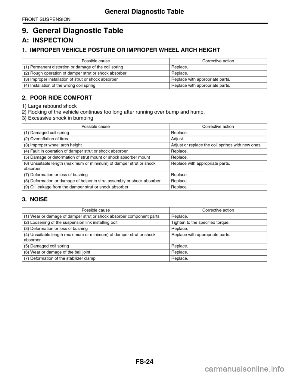
9. General Diagnostic Table
A: INSPECTION
1. IMPROPER VEHICLE POSTURE OR IMPROPER WHEEL ARCH HEIGHT
2. POOR RIDE COMFORT
1) Large rebound shock
2) Rocking of the vehicle continues too long after running over bump and hump.
3) Excessive shock in bumping
3. NOISE
Po ss ibl e c a us e C o r r e ct ive ac ti o n
(1) Permanent distortion or damage of the coil spring Replace.
(2) Rough operation of damper strut or shock absorber Replace.
(3) Improper installation of strut or shock absorber Replace with appropriate parts.
(4) Installation of the wrong coil spring Replace with appropriate parts.
Po ss ibl e ca us e C or r e ct i ve a ct io n
(1) Damaged coil spring Replace.
(2) Overinflation of tires Adjust.
(3) Improper wheel arch height Adjust or replace the coil springs with new ones.
(4) Fault in operation of damper strut or shock absorber Replace.
(5) Damage or deformation of strut mount or shock absorber mount Replace.
(6) Unsuitable length (maximum or minimum) of damper strut or shock
absorber
Replace with appropriate parts.
(7) Deformation or loss of bushing Replace.
(8) Deformation or damage of helper in strut assembly or shock absorber Replace.
(9) Oil leakage from the damper strut or shock absorber Replace.
Po ss ibl e c a us e C o r r e ct ive ac ti o n
(1) Wear or damage of damper strut or shock absorber component parts Replace.
(2) Loosening of the suspension link installing bolt Tighten to the specified torque.
(3) Deformation or loss of bushing Replace.
(4) Unsuitable length (maximum or minimum) of damper strut or shock
absorber
Replace with appropriate parts.
(5) Damaged coil spring Replace.
(6) Wear or damage of the ball joint Replace.
(7) Deformation of the stabilizer clamp Replace.
Page 875 of 2453

PB-4
Parking Brake Pedal
PARKING BRAKE
2. Parking Brake Pedal
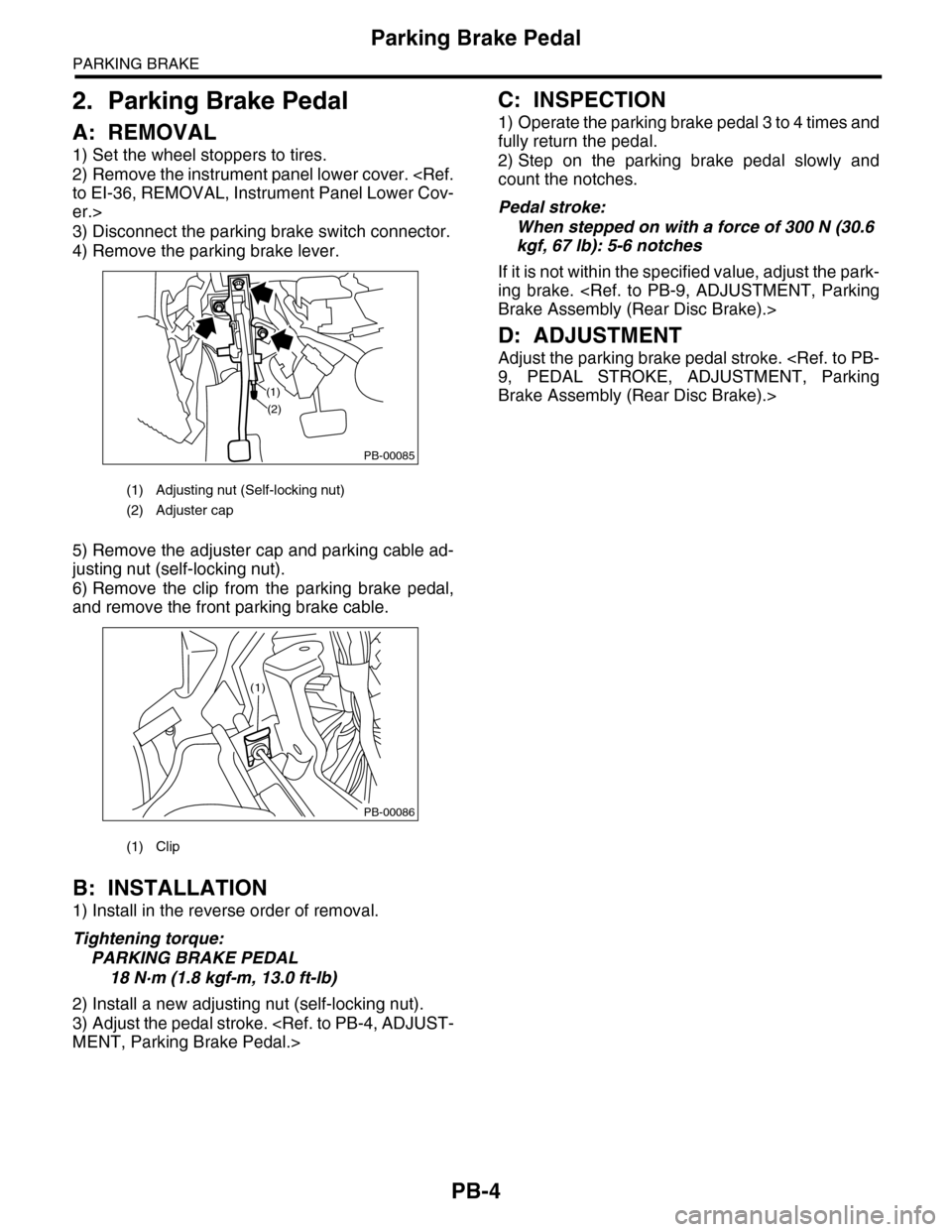
A: REMOVAL
1) Set the wheel stoppers to tires.
2) Remove the instrument panel lower cover.
er.>
3) Disconnect the parking brake switch connector.
4) Remove the parking brake lever.
5) Remove the adjuster cap and parking cable ad-
justing nut (self-locking nut).
6) Remove the clip from the parking brake pedal,
and remove the front parking brake cable.
B: INSTALLATION
1) Install in the reverse order of removal.
Tightening torque:
PARKING BRAKE PEDAL
18 N·m (1.8 kgf-m, 13.0 ft-lb)
2) Install a new adjusting nut (self-locking nut).
3) Adjust the pedal stroke.
C: INSPECTION
1) Operate the parking brake pedal 3 to 4 times and
fully return the pedal.
2) Step on the parking brake pedal slowly and
count the notches.
Pedal stroke:
When stepped on with a force of 300 N (30.6
kgf, 67 lb): 5-6 notches
If it is not within the specified value, adjust the park-
ing brake.
D: ADJUSTMENT
Adjust the parking brake pedal stroke.
Brake Assembly (Rear Disc Brake).>
(1) Adjusting nut (Self-locking nut)
(2) Adjuster cap
(1) Clip
PB-00085
(1)
(2)
PB-00086
(1)
Page 929 of 2453

PS-49
General Diagnostic Table
POWER ASSISTED SYSTEM (POWER STEERING)
10.General Diagnostic Table
A: INSPECTION
*1 If the tires or wheels are wider than standard, the load to the power steering system is increased. Accordingly, in a condition,
for example before fluid warms-up, relief valve may work before reaching maximum turning angle. In this case, steering effort
may be heavy. When the measured hydraulic pressure is normal, there is no abnormal thing. *2 In cold weather, flow resistance will increase due to the cold hydraulic fluid, and steering effort will be heavier. After warming-up en-
gine, turn the steering wheel from stop to stop several times to warm-up fluid. If steering effort reduces normally, function is normal. *3 I n c o l d w e a t h e r o r w i t h i n s u f f i c i e n t w a r m – u p o f t h e e n g i n e , s t e e r i n g e f f o r t m a y b e h e a v y d u e t o e x c e s s i v e d r o p o f i d l e r p m w h en
turning the steering wheel. In this case, start the vehicle with increasing engine speed than usual. If steering effort reduces nor-
mally, function is normal.
Tr o u b l e P o s s i b l e c a u s e C o r r e c t i v e a c t i o n
•Steering effort is heavy in all
ranges.
•Steering effort is heavy at
stand still.
•Steering wheel vibrates
when turning.
1. Pulley belt
•Unequal length of pulley belts
•Contact with oil or grease
•Looseness or damage of the pulley belt
•Poor uniformity of the pulley belt cross section
•Pulley belt touches to pulley bottom
•Poor revolution of pulleys (except oil pump pulley)
•Poor revolution of oil pump pulley
Adjust or replace.
2. Tire and wheel
•Improper tire out of specifications*1
•Improper wheel out of specifications*1
•Tires not properly inflated
Replace or reinflate.
3. Fluid
•Low fluid level
•Air entry in fluid
•Entry of dust in the fluid
•Fluid deterioration
•Inadequate warm–up of fluid *2
Refill, bleed air,
replace or instruct cus-
tomer.
4. Idle speed
•Lower idle speed
•Excessive drop of idle speed at start or when turning the steering
wheel *3
Adjust or instruct cus-
tomer.
5. Measure the hydraulic pressure.
Replace the problem
parts.
6. Measure the steering wheel effort.
•Vehicle leads to one side or
the other.
•Returning force of steering
wheel to center is poor.
•Steering wheel vibrates
when turning.
1. Fluid line
•Folded hose
•Flattened pipe
Correct or replace.
2. Tire and wheel
•Flat tire
•Mixed use of different tires
•Mixed use of different wheels
•Abnormal wear of tire
•Unequal tread remaining
•Unequal pressure of tire
Adjust, fix or replace.
3. Front alignment
•Improper or unequal caster
•Improper or unequal toe–in
•Loose suspension connections
Adjust or retighten.
4. Others
•Damaged joint assembly
•Unbalanced height
•Unbalanced weight
Replace, adjust or
instruct customer.
5. Measure the steering wheel effort.
Page 950 of 2453

RS-17
General Diagnostic Table
REAR SUSPENSION
10.General Diagnostic Table
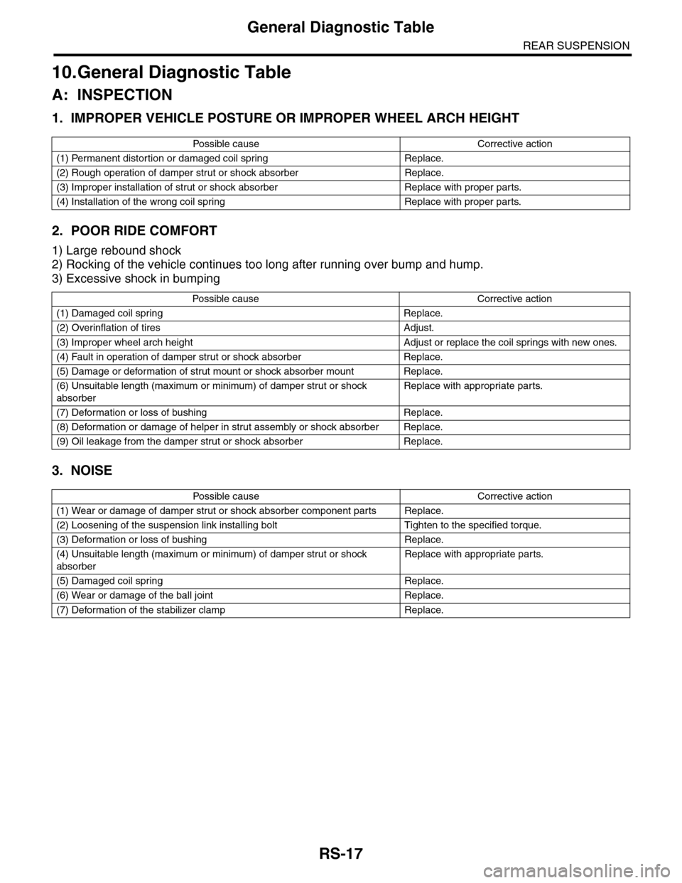
A: INSPECTION
1. IMPROPER VEHICLE POSTURE OR IMPROPER WHEEL ARCH HEIGHT
2. POOR RIDE COMFORT
1) Large rebound shock
2) Rocking of the vehicle continues too long after running over bump and hump.
3) Excessive shock in bumping
3. NOISE
Po ss ibl e c a us e C o r r e ct ive ac ti o n
(1) Permanent distortion or damaged coil spring Replace.
(2) Rough operation of damper strut or shock absorber Replace.
(3) Improper installation of strut or shock absorber Replace with proper parts.
(4) Installation of the wrong coil spring Replace with proper parts.
Po ss ibl e ca us e C or r e ct i ve a ct io n
(1) Damaged coil spring Replace.
(2) Overinflation of tires Adjust.
(3) Improper wheel arch height Adjust or replace the coil springs with new ones.
(4) Fault in operation of damper strut or shock absorber Replace.
(5) Damage or deformation of strut mount or shock absorber mount Replace.
(6) Unsuitable length (maximum or minimum) of damper strut or shock
absorber
Replace with appropriate parts.
(7) Deformation or loss of bushing Replace.
(8) Deformation or damage of helper in strut assembly or shock absorber Replace.
(9) Oil leakage from the damper strut or shock absorber Replace.
Po ss ibl e c a us e C o r r e ct ive ac ti o n
(1) Wear or damage of damper strut or shock absorber component parts Replace.
(2) Loosening of the suspension link installing bolt Tighten to the specified torque.
(3) Deformation or loss of bushing Replace.
(4) Unsuitable length (maximum or minimum) of damper strut or shock
absorber
Replace with appropriate parts.
(5) Damaged coil spring Replace.
(6) Wear or damage of the ball joint Replace.
(7) Deformation of the stabilizer clamp Replace.
Page 953 of 2453

TPM(diag)-3
General Description
TIRE PRESSURE MONITORING SYSTEM (DIAGNOSTICS)
2. General Description
A: CAUTION
1. SRS AIRBAG SYSTEM
Airbag system wiring harness is routed near the
TPM control module.
CAUTION:
•Wiring harnesses of all airbag system are yel-
low. Do not use the electrical test equipment on
these circuits.
•Be careful not to damage the airbag system
wiring harness when servicing the tire pressure
monitoring control module.
2. TIRE PRESSURE MONITORING CON-
TROL MODULE
•If the alteration of tire rotation, the installation po-
sition or the replacement of transmitter is per-
formed, ID registration for the transmitter is
required.
Monitor.>
•When adjusting tire pressure indoors in winter,
there is a big temperature difference between the
indoor facilities and outside. Once the car is outside
where the temperature is lower, the air pressure in
the tires will drop, causing the tire pressure warning
light to come on, even if the pressure in the tires
was adjusted to standard values indoors. To avoid
this, it is necessary to adjust the tire pressure to the
high side in consideration of the difference in tem-
perature between inside and outside.
B: INSPECTION
Before performing diagnosis, check the following
item which might affect the quality of the tire pres-
sure monitoring system.
1. TIRE
•Inspect that the tire pressure is within the speci-
fication while the tire is cool. (Refer to Tire Caution
Label.)
•Check the tires for damage or the insertion of for-
eign matters.
2. BATTERY
Check that amount of battery fluid, gravity and volt-
age are within the specifications.
Standard voltage: 12 V or more
Specific gravity: 1.260 or more
Te m p e r a -
ture
°C (°F)
Indoor
tempera-
ture
15.5 (60)
Ambient
tempera-
ture
–1 (30) –12 (10) –23 (–10)
Reference
for adjusting
tire pres-
sure
kPa (psi)
Fr o n t 25 0 ( 36 ) 26 5 ( 3 8 ) 2 8 0 ( 4 0)
Rear 240 (35) 255 (37) 270 (39)
Page 959 of 2453
![SUBARU TRIBECA 2009 1.G Service Workshop Manual TPM(diag)-9
Subaru Select Monitor
TIRE PRESSURE MONITORING SYSTEM (DIAGNOSTICS)
2. DATA DISPLAY
1) On the «Main Menu» display screen, select the {Each System Check} and press the [YES] key.
2) On th SUBARU TRIBECA 2009 1.G Service Workshop Manual TPM(diag)-9
Subaru Select Monitor
TIRE PRESSURE MONITORING SYSTEM (DIAGNOSTICS)
2. DATA DISPLAY
1) On the «Main Menu» display screen, select the {Each System Check} and press the [YES] key.
2) On th](/manual-img/17/7322/w960_7322-958.png)
TPM(diag)-9
Subaru Select Monitor
TIRE PRESSURE MONITORING SYSTEM (DIAGNOSTICS)
2. DATA DISPLAY
1) On the «Main Menu» display screen, select the {Each System Check} and press the [YES] key.
2) On the «System Selection Menu» display screen, select the {Tire Pressure Monitor} and press the [YES]
key.
3) Press the [YES] key after the {Tire Pressure Monitor} is displayed.
4) On the «Tire pressure monitor diagnosis» display screen, select the {Data Display}, and then press the
[YES] key, then necessary data will be displayed.
•A list of the support data is shown in the following table.
3. CLEAR MEMORY
1) On the «Main Menu», select the {2. Each Sys-
tem Check} and press the [YES] key.
2) On the «System Selection Menu» display
screen, select the {Tire Pressure Monitor} and
press the [YES] key.
3) Press the [YES] key after the {Tire Pressure
Monitor} is displayed.
4) On the «Tire Pressure Monitor Diagnosis» dis-
play screen, select the {Memory Clear} and press
the [YES] key.
5) When «Done» and «Turn ignition switch OFF»
are shown on the display screen, turn the Subaru
Select Monitor and ignition switch to OFF.
NOTE:
For details concerning operation procedure, refer
to the “SUBARU SELECT MONITOR OPERATION
MANUAL”.
4. REGISTER TRANSMITTER ID
Perform the procedures below to register the trans-
mitter.
•Transmitter replaced.
•Switched the position of the transmitter (rotated
tires)
•Replaced the tire pressure monitoring control
module.
NOTE:
•If registration of the transmitter ID is not possible
after 2 attempts, replace the tire pressure monitor-
ing control module.
REMOVAL, Tire Pressure Monitoring System.>
•If the ignition switch and Subaru Select Monitor
power are turned OFF while registering the trans-
mitter, or if registration is not possible for more than
5 minutes, the registration mode is cancelled.
•When rotating tires, there is no affect on the per-
formance or functions of the tire pressure monitor-
ing control module even if the transmitter (ID) is not
registered, however, the tire position displayed on
the Subaru Select Monitor will be incorrect.
1) Adjust all tire pressures to the specifications.
NOTE:
Refer to the tire caution label on the driver's side
door for the correct tire pressure.
Display Contents to be monitored Unit of measure
FR FN Code
LEARN, LOW BAT, OFF, WAKE, RE ME, NOR-
MAL
LEARN: Transmitted transmitter ID using the transmit-
ter registration tool
LOW BAT: Transmitter battery voltage running low
OFF: Transmitter function stops (no data transmission)
RE ME: Tire air changes ±8.4 kPa
WA K E : S t a r t ed tr an sm it t i ng da t a f r o m a s t op p ed st a te
NORMAL: Conditions other than above
FL FN Code
RR FN Code
RL FN Code
FR tire pressureVa l u e c o nve r t e d t o t i r e p r e s s u r e f r o m d a t a d e l i v -
ered from transmitter is displayed.
(It may be different from values measured by the
direct contact meter.)
kPa, psig, mmHg, inHg
FL tire pressurekPa, psig, mmHg, inHg
RR tire pressurekPa, psig, mmHg, inHg
RL tire pressurekPa, psig, mmHg, inHg
Ve h i c l e S p e e dVe h i c l e s p e e d s i g n a l w h i c h i s i n p u t i n c o n t r o l
module.km/h, MPH
Pressure warning Threshold where tire pressure warning light lights kPa, psig, mmHg, inHg
Return pressureThreshold where tire pressure warning light goes
outkPa, psig, mmHg, inHg
Page 972 of 2453

TPM(diag)-22
Tire Pressure Warning Light/Trouble Indicator Light Illumination Pattern (DTC)
TIRE PRESSURE MONITORING SYSTEM (DIAGNOSTICS)
C: TIRE PRESSURE WARNING LIGHT DOES NOT COME OFF
DETECTING CONDITION:
•Defective combination meter
•Defective harness
•Tires pressure drop
•Transmitter ID not registered
TROUBLE SYMPTOM:
Tire pressure warning light does not go off after engine starts.
WIRING DIAGRAM:
TPM00019
TO POWER SUPPLY CIRCUIT
FB-36 F/B FUSE NO.5(IG)
26
COMBINATIONMETERA:i10
A3
A10
TIRE INFLATION PRESSURE WARNINGLIGHT
FB-17F/B FUSE NO. 7 (B)
i102
R167
R211
FB-48F/B FUSE NO. 4 (IG)
A4
INVERTING CIRCUIT
15
5
9
TPM CONTROL MODULE
i102
1238910411 12 1314 15 16567
A:i10
12345 678910111219 20 2113 14 15 161718 22
R211
123456789101112
Step Check Yes No
1CHECK DIAGNOSTIC TROUBLE CODE
(DTC)
Connect Subaru Select Monitor, read Diagnos-
tic Trouble Code.
OPERATION, Subaru Select Monitor.>
Is DTC displayed? Perform the diag-
nosis according to
DTC.
of Diagnostic Trou-
ble Code (DTC).>
Go to step 2.
Page 978 of 2453

TPM(diag)-28
Diagnostic Procedure with Diagnostic Trouble Code (DTC)
TIRE PRESSURE MONITORING SYSTEM (DIAGNOSTICS)
11.Diagnostic Procedure with Diagnostic Trouble Code (DTC)
A: DTC 11 FL AIR PRESSURE DECREASE
NOTE:
Refer to DTC 14 for diagnostic procedure.
B: DTC 12 FR AIR PRESSURE DECREASE
NOTE:
Refer to DTC 14 for diagnostic procedure.
C: DTC 13 RR AIR PRESSURE DECREASE
NOTE:
Refer to DTC 14 for diagnostic procedure.
D: DTC 14 RL AIR PRESSURE DECREASE
DTC DETECTING CONDITION:
Inflation pressure of each tire reduces under specifications (188 kPs (1.9 kgf/cm2, 27.3 psi) or less).
TROUBLE SYMPTOM:
Tire pressure warning light illuminates.
CAUTION:
When driving vehicle to perform driving test, there should be always 2 persons (driver and checker)
to check.
Step Check Yes No
1CHECK THE TIRES.
Lift-up the vehicle and check for damage in the
tires.
Are there cracks or damage? Replace the tire.
Go to step 2.
2CHECK THE TIRES.
Check the tire air pressure.
Is the tire pressure in the spec-
ifications?
Go to step 3.Adjust the air pres-
sure.
3CHECK THE TRANSMITTER
Drive the vehicle at a speed more than 40 km/h
(25 MPH) and compare the data from the
transmitter on the four wheels.
Is there a transmitter with dif-
ferent data?
Replace the trans-
mitter (tire pres-
sure sensor)
Pressure Monitor-
ing System.>.
Go to step 4.
4PERFORM DRIVING TEST.
1) Perform the clear memory mode.
Subaru Select Monitor.>
2) Perform the driving test.
Mode.>
3) Read the DTC.
OPERATION, Subaru Select Monitor.>
Is DTC displayed? Record the DTC.
Pe r for m t h e r e pa i r
according to DTC.
of Diagnostic Trou-
ble Code (DTC).>
Finish the diagno-
sis.