Page 1993 of 2453
PM-10
V-belt
PERIODIC MAINTENANCE SERVICES
6. V-belt
A: INSPECTION
1) Replace the belts if cracks, fraying or wear are
found.
2) Make sure that the V-belt automatic belt tension
indicator (A) is within the range of its use limit (D).
B: REPLACEMENT
1) Remove the cover.
2) Fit the tool to the belt tensioner mounting bolt.
3) Turn the tool in the direction of the arrow, and
loosen the V-belt to remove it.
4) Install in the reverse order of removal.
(A) Indicator
(B) Generator
(C) Power steering oil pump
(D) Service limit
(B)
(A)
(D)
(C)
ME-00475
(1) Power steering oil pump
(2) Belt tension adjuster
(3) Crank pulley
(4) A/C compressor
(5) Belt idler
(6) Generator
PM-00301
(1)(6)
(4)
(5)(2)
(3)ME-00474
Page 2040 of 2453
5AT-24
General Description
AUTOMATIC TRANSMISSION
499587100 OIL SEAL
INSTALLER
Used for installing the oil seal.
499787500 ADAPTER Used for removing and installing drive pinion lock
nut.
499575400 GAUGE Used for measuring height of total end play.
18762AA000 COMPRESSOR
SPECIAL TOOL
Used for disassembling multi-plate clutch for shift
transmission.
499755602
(Newly adopted tool)
PRESS Used for installing the parking gear.
ILLUSTRATION TOOL NUMBER DESCRIPTION REMARKS
ST-499587100
ST-499787500
ST-499575400
ST18762AA000
ST-499755602
Page 2079 of 2453

5AT-63
Extension Case
AUTOMATIC TRANSMISSION
24.Extension Case
A: REMOVAL
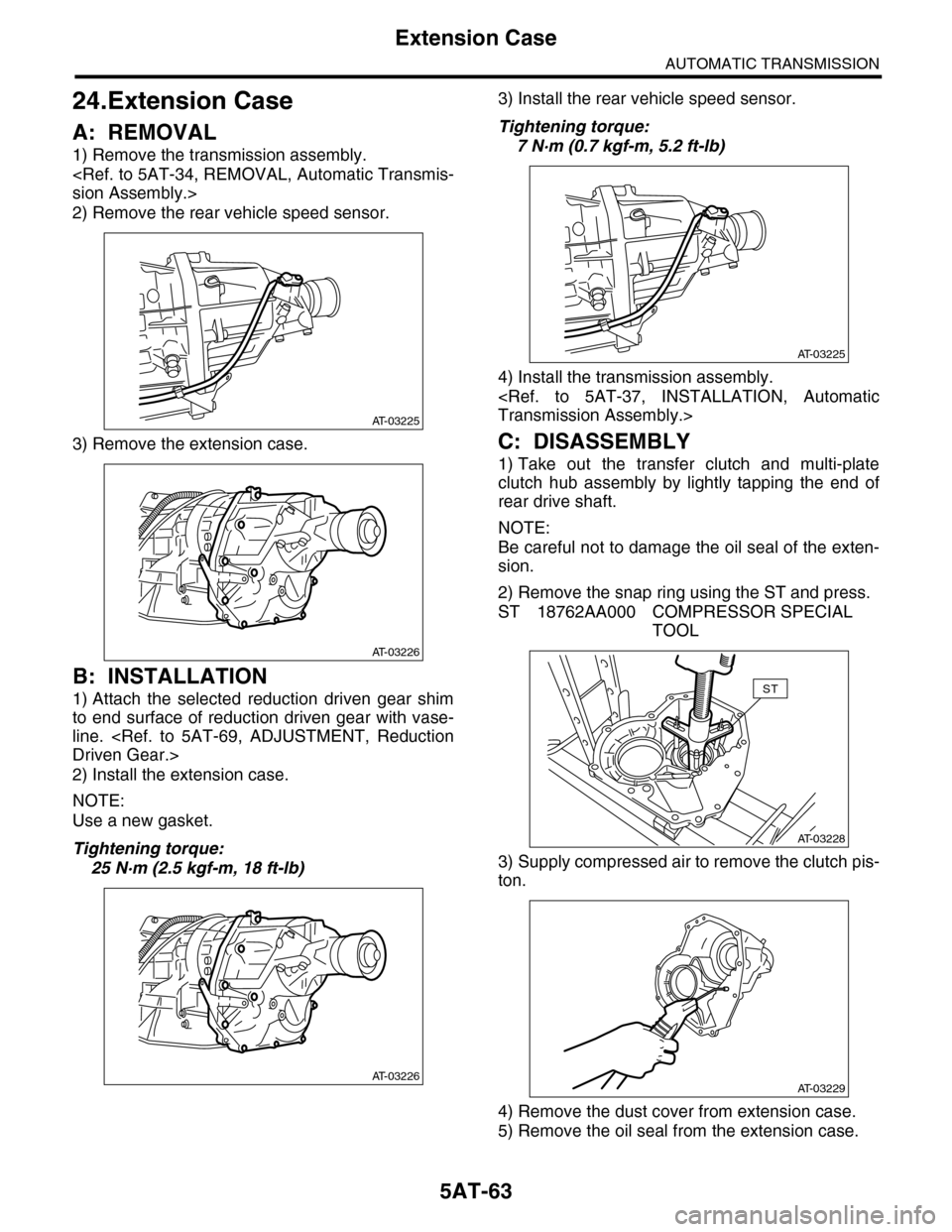
1) Remove the transmission assembly.
sion Assembly.>
2) Remove the rear vehicle speed sensor.
3) Remove the extension case.
B: INSTALLATION
1) Attach the selected reduction driven gear shim
to end surface of reduction driven gear with vase-
line.
Driven Gear.>
2) Install the extension case.
NOTE:
Use a new gasket.
Tightening torque:
25 N·m (2.5 kgf-m, 18 ft-lb)
3) Install the rear vehicle speed sensor.
Tightening torque:
7 N·m (0.7 kgf-m, 5.2 ft-lb)
4) Install the transmission assembly.
Transmission Assembly.>
C: DISASSEMBLY
1) Take out the transfer clutch and multi-plate
clutch hub assembly by lightly tapping the end of
rear drive shaft.
NOTE:
Be careful not to damage the oil seal of the exten-
sion.
2) Remove the snap ring using the ST and press.
ST 18762AA000 COMPRESSOR SPECIAL
TOOL
3) Supply compressed air to remove the clutch pis-
ton.
4) Remove the dust cover from extension case.
5) Remove the oil seal from the extension case.
AT-03225
AT-03226
AT-03226
AT-03225
AT-03228
ST
AT-03229
Page 2080 of 2453
5AT-64
Extension Case
AUTOMATIC TRANSMISSION
D: ASSEMBLY
1) Press-fit the new oil seal using ST and the press.
ST 498057300 INSTALLER
2) Press-fit the dust cover.
3) Insert the transfer clutch assembly, spring re-
tainer, return spring and clutch spring retainer.
4) Using the ST and compressor, install the snap
ring.
ST 18762AA000 COMPRESSOR SPECIAL
TOOL
5) Install the transfer clutch.
STALLATION, Transfer Clutch.>
6) Install the multi-plate hub assembly.
E: INSPECTION
•Use compressed air to make sure the extension
case routes are not clogged or leaking.
•Inspect the extension end play, and adjust it to
within the standard value.
(A) Clutch spring retainer
(B) Return spring
(C) Spring retainer
(D) Transfer clutch piston
AT-03230
(A)(B)(C)
(D)
AT-03228
ST
Page 2094 of 2453

5AT-78
Oil Pump Cover
AUTOMATIC TRANSMISSION
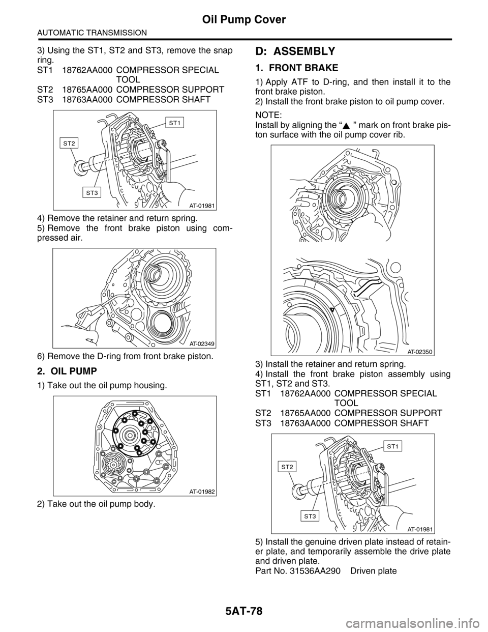
3) Using the ST1, ST2 and ST3, remove the snap
ring.
ST1 18762AA000 COMPRESSOR SPECIAL
TOOL
ST2 18765AA000 COMPRESSOR SUPPORT
ST3 18763AA000 COMPRESSOR SHAFT
4) Remove the retainer and return spring.
5) Remove the front brake piston using com-
pressed air.
6) Remove the D-ring from front brake piston.
2. OIL PUMP
1) Take out the oil pump housing.
2) Take out the oil pump body.
D: ASSEMBLY
1. FRONT BRAKE
1) Apply ATF to D-ring, and then install it to the
front brake piston.
2) Install the front brake piston to oil pump cover.
NOTE:
Install by aligning the “ ” mark on front brake pis-
ton surface with the oil pump cover rib.
3) Install the retainer and return spring.
4) Install the front brake piston assembly using
ST1, ST2 and ST3.
ST1 18762AA000 COMPRESSOR SPECIAL
TOOL
ST2 18765AA000 COMPRESSOR SUPPORT
ST3 18763AA000 COMPRESSOR SHAFT
5) Install the genuine driven plate instead of retain-
er plate, and temporarily assemble the drive plate
and driven plate.
Part No. 31536AA290 Driven plate
AT-01981
ST1
ST2
ST3
AT-02349
AT-01982
AT-02350
AT-01981
ST1
ST2
ST3
Page:
< prev 1-8 9-16 17-24