2009 SUBARU TRIBECA ac compressor oil
[x] Cancel search: ac compressor oilPage 363 of 2453
AC-37
Evaporator
HVAC SYSTEM (HEATER, VENTILATOR AND A/C)
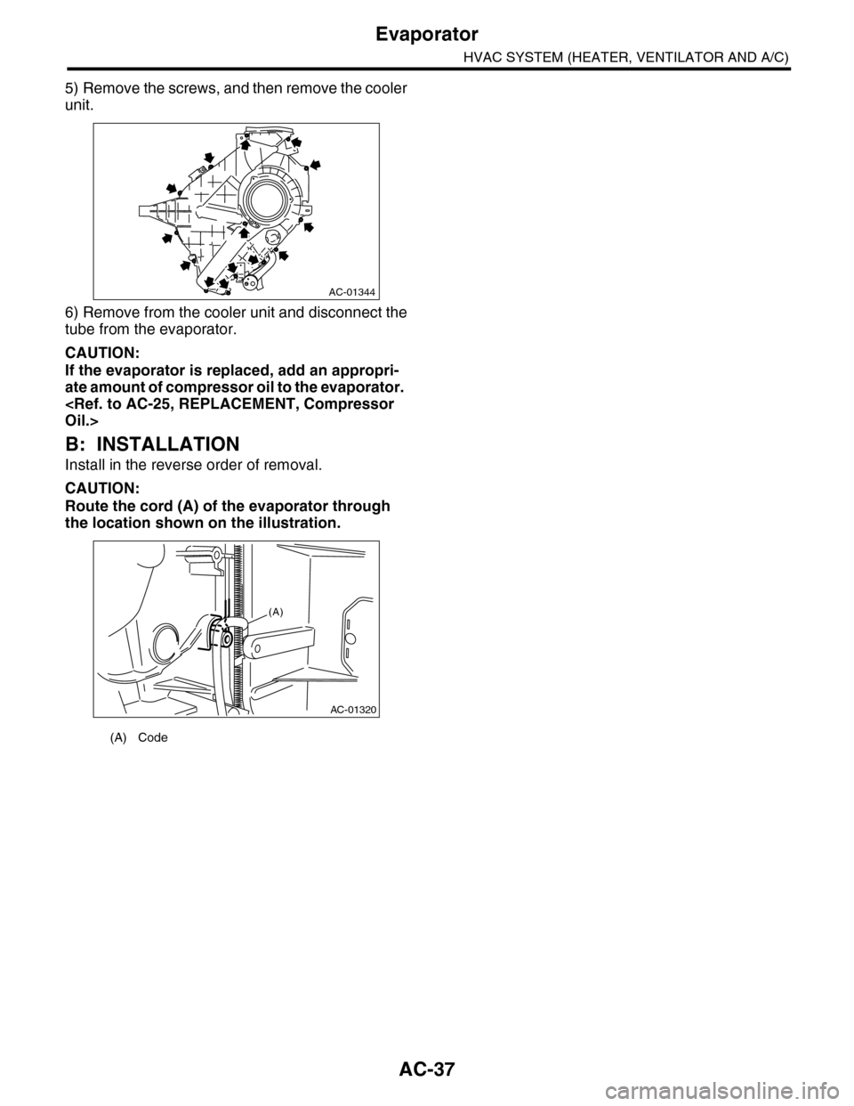
5) Remove the screws, and then remove the cooler
unit.
6) Remove from the cooler unit and disconnect the
tube from the evaporator.
CAUTION:
If the evaporator is replaced, add an appropri-
ate amount of compressor oil to the evaporator.
B: INSTALLATION
Install in the reverse order of removal.
CAUTION:
Route the cord (A) of the evaporator through
the location shown on the illustration.
(A) Code
AC-01344
AC-01320
(A)
Page 853 of 2453
FS-5
General Description
FRONT SUSPENSION
2. GENERAL TOOL
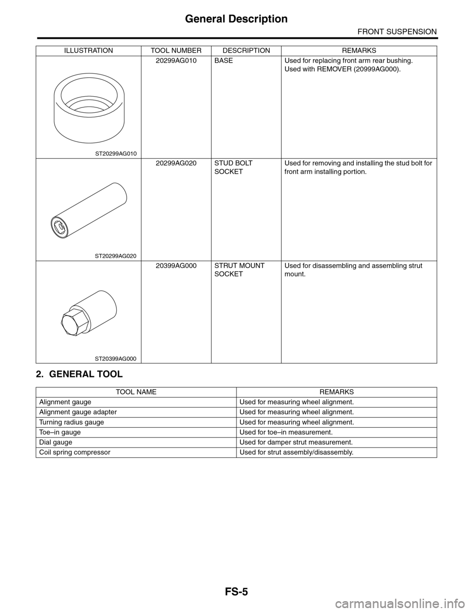
20299AG010 BASE Used for replacing front arm rear bushing.
Used with REMOVER (20999AG000).
20299AG020 STUD BOLT
SOCKET
Used for removing and installing the stud bolt for
front arm installing portion.
20399AG000 STRUT MOUNT
SOCKET
Used for disassembling and assembling strut
mount.
TOOL NAME REMARKS
Alignment gauge Used for measuring wheel alignment.
Alignment gauge adapter Used for measuring wheel alignment.
Tu r n i n g r a d i u s g a u g e U s e d f o r m e a s u r i n g w h e e l a l i g n m e n t .
To e – i n g a u g e U s e d f o r t o e – i n m e a s u r e m e n t .
Dial gauge Used for damper strut measurement.
Coil spring compressor Used for strut assembly/disassembly.
ILLUSTRATION TOOL NUMBER DESCRIPTION REMARKS
ST20299AG010
ST20299AG020
ST20399AG000
Page 868 of 2453

FS-20
Front Strut
FRONT SUSPENSION
C: DISASSEMBLY
1) Using a coil spring compressor, compress the
coil spring.
2) Using the ST, remove the self–locking nut.
ST 20399AG000 STRUT MOUNT SOCKET
3) Remove the strut mount, spacer and upper
spring seat from strut.
4) Gradually decrease the compression force of
compressor, and remove the coil spring.
5) Remove the dust cover and helper spring.
D: ASSEMBLY
1) Before installing the coil spring, strut mount, etc.
on strut, check for the presence of air in the damp-
ening force generating mechanism of the strut
since air prevents proper dampening force produc-
tion.
2) Checking for presence of air
(1) Place the strut vertically with the piston rod
facing up.
(2) Move the piston rod to the center of its entire
stroke.
(3) While holding the piston rod end with fin-
gers, move the rod up and down.
(4) If the piston rod moves more than 10 mm
(0.39 in) in the former step, purge air from the
strut.
3) Air purging procedure
(1) Place the strut vertically with the piston rod
facing up.
(2) Fully extend the piston rod.
(3) With the piston rod fully extended, place the
piston rod side down. The strut must stand ver-
tically.
(4) Fully retract the piston rod.
(5) Repeat 3 or 4 times from the step (1).
NOTE:
After purging air from the strut, be sure to place the
strut with the piston rod facing up. If the strut is laid
down for any reason, check for the entry of air in ac-
cordance with “Checking for presence of air”
4) Using a coil spring compressor, compress the
coil spring.
NOTE:
Make sure that the vertical install direction of the
coil spring is as shown in the figure.
5) Set the coil spring correctly so that its end face
seats well in the spring seat as shown in the figure.
6) Install the helper and dust cover to the piston
rod.
FS-00040
FS-00041
ST
(1) Place the flat end on the top side.
(2) Identification paint
(1) Coil spring end face
FS-00216
(2)
(1)
FS-00043
(1)
Page 939 of 2453

RS-6
General Description
REAR SUSPENSION
2. GENERAL TOOL
28099PA090 OIL SEAL PROTEC-
TOR
•Used for installing the rear drive shaft to the
rear differential.
•For oil seal protection
TOOL NAME REMARKS
Alignment tester Used for measuring wheel alignment.
To e – i n g a u g e U s e d f o r t o e – i n m e a s u r e m e n t .
Jack Used for removing and installing suspension.
Bearing puller Used for removing bushings.
Coil spring compressor Used for disassembling and assembling shock absorber.
ILLUSTRATION TOOL NUMBER DESCRIPTION REMARKS
ST28099PA090
Page 1189 of 2453
EN(H6DO)(diag)-28
Subaru Select Monitor
ENGINE (DIAGNOSTICS)
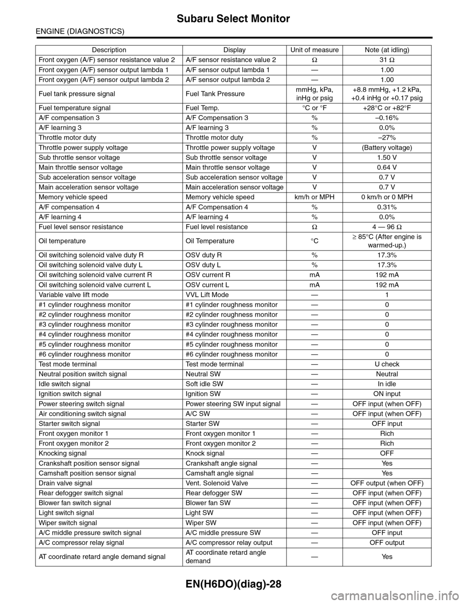
Fr o nt ox yg e n ( A / F) s en so r r es is t an ce val ue 2 A / F s en s or r e si st a nc e val u e 2Ω31 Ω
Fr o nt ox yg e n ( A / F) s en so r ou t p ut la m bd a 1 A / F s en s or o ut p ut l am bd a 1 — 1 . 00
Fr o nt ox yg e n ( A / F) s en so r ou t p ut la m bd a 2 A / F s en s or o ut p ut l am bd a 2 — 1 . 00
Fuel tank pressure signal Fuel Tank PressuremmHg, kPa,
inHg or psig
+8.8 mmHg, +1.2 kPa,
+0.4 inHg or +0.17 psig
Fuel temperature signal Fuel Temp. °C or °F +28°C or +82°F
A/F compensation 3 A/F Compensation 3 % –0.16%
A/F learning 3 A/F learning 3 % 0.0%
Throttle motor duty Throttle motor duty % –27%
Throttle power supply voltage Throttle power supply voltage V (Battery voltage)
Sub throttle sensor voltage Sub throttle sensor voltage V 1.50 V
Main throttle sensor voltage Main throttle sensor voltage V 0.64 V
Sub acceleration sensor voltage Sub acceleration sensor voltage V 0.7 V
Main acceleration sensor voltage Main acceleration sensor voltage V 0.7 V
Memory vehicle speed Memory vehicle speed km/h or MPH 0 km/h or 0 MPH
A/F compensation 4 A/F Compensation 4 % 0.31%
A/F learning 4 A/F learning 4 % 0.0%
Fuel level sensor resistance Fuel level resistanceΩ4 — 96 Ω
Oil temperature Oil Temperature °C≥ 85°C (After engine is
warmed-up.)
Oil switching solenoid valve duty R OSV duty R % 17.3%
Oil switching solenoid valve duty L OSV duty L % 17.3%
Oil switching solenoid valve current R OSV current R mA 192 mA
Oil switching solenoid valve current L OSV current L mA 192 mA
Va r i a b l e va l v e l i f t m o d e V V L L i f t M o d e — 1
#1 cylinder roughness monitor #1 cylinder roughness monitor — 0
#2 cylinder roughness monitor #2 cylinder roughness monitor — 0
#3 cylinder roughness monitor #3 cylinder roughness monitor — 0
#4 cylinder roughness monitor #4 cylinder roughness monitor — 0
#5 cylinder roughness monitor #5 cylinder roughness monitor — 0
#6 cylinder roughness monitor #6 cylinder roughness monitor — 0
Te s t m o d e t e r m i n a l Te s t m o d e t e r m i n a l — U c h e c k
Neutral position switch signal Neutral SW — Neutral
Idle switch signal Soft idle SW — In idle
Ignition switch signal Ignition SW — ON input
Pow er s te e r in g sw it c h s ig n al Powe r st ee r i ng S W i n pu t si gn a l — O FF i np u t ( w h e n OF F )
Air conditioning switch signal A/C SW — OFF input (when OFF)
Starter switch signal Starter SW — OFF input
Fr o nt ox yg e n mo n it o r 1 Fr o n t oxy ge n m on i to r 1 — Ri ch
Fr o nt ox yg e n mo n it o r 2 Fr o n t oxy ge n m on i to r 2 — Ri ch
Knocking signal Knock signal — OFF
Crankshaft position sensor signal Crankshaft angle signal — Yes
Camshaft position sensor signal Camshaft angle signal — Yes
Drain valve signal Vent. Solenoid Valve — OFF output (when OFF)
Rear defogger switch signal Rear defogger SW — OFF input (when OFF)
Blower fan switch signal Blower fan SW — OFF input (when OFF)
Light switch signal Light SW — OFF input (when OFF)
Wiper switch signal Wiper SW — OFF input (when OFF)
A/C middle pressure switch signal A/C middle pressure SW — OFF input
A/C compressor relay signal A/C compressor relay output — OFF output
AT c o o r d i n a t e r e t a r d a n g l e d e m a n d s i g n a lAT c o o r d i n a t e r e t a r d a n g l e
demand—Yes
Description Display Unit of measure Note (at idling)
Page 1193 of 2453
![SUBARU TRIBECA 2009 1.G Service Workshop Manual EN(H6DO)(diag)-32
Subaru Select Monitor
ENGINE (DIAGNOSTICS)
7. LED OPERATION MODE FOR ENGINE
1) On the «Main Menu» display screen, select the {Each System Check} and press the [YES] key.
2) On the SUBARU TRIBECA 2009 1.G Service Workshop Manual EN(H6DO)(diag)-32
Subaru Select Monitor
ENGINE (DIAGNOSTICS)
7. LED OPERATION MODE FOR ENGINE
1) On the «Main Menu» display screen, select the {Each System Check} and press the [YES] key.
2) On the](/manual-img/17/7322/w960_7322-1192.png)
EN(H6DO)(diag)-32
Subaru Select Monitor
ENGINE (DIAGNOSTICS)
7. LED OPERATION MODE FOR ENGINE
1) On the «Main Menu» display screen, select the {Each System Check} and press the [YES] key.
2) On the «System Selection Menu» display screen, select the {Engine} and press the [YES] key.
3) Press the [YES] key after the information of engine type has been displayed.
4) On the «Engine Diagnosis» display screen, select the {Current Data Display/Save}, and then press the
[YES] key.
5) On the «Data Display» screen, select the {Data LED Display} and press the [YES] key.
6) Using the scroll key, scroll the display screen up or down until the desired data is shown.
•A list of the support data is shown in the following table.
NOTE:
For detailed operation procedure, refer to the “SUBARU SELECT MONITOR OPERATION MANUAL”.
Description Display Message When LED “ON” required
Te s t m o d e s i g n a l Te s t m o d e t e r m i n a l D c h e c k / U c h e c k D c h e c k
Neutral position switch signal Neutral SW Neutral/Other than neutral Neutral
Idle switch signal Soft idle SW Idle/Other than idle In idle
Ignition switch signal Ignition SW ON Input/OFF Input ON input
Pow er s te e r in g sw it c h s ig n al Pow er s te e r in g S W ON I np u t/ O FF I np u t ON i np ut
Air conditioning switch signal A/C SW ON Input/OFF Input ON input
Starter switch signal Starter SW ON Input/OFF Input ON input
Fr o nt ox yg e n mo n it o r 1 Ft O 2 mo n it o r 1 Le a n/ Ri ch Ric h
Fr o nt ox yg e n mo n it o r 2 Ft O 2 mo n it o r 2 Le a n/ Ri ch Ric h
Knocking signal Knock signal Yes/No Yes
Crankshaft position sensor signal Crankshaft angle signal Yes/No Yes
Camshaft position sensor signal Camshaft angle signal Yes/No Yes
Rear defogger switch signal Rear defogger SW ON Input/OFF Input ON input
Blower fan switch signal Blower fan SW ON Input/OFF Input ON input
Light switch signal Light SW ON Input/OFF Input ON input
Wiper switch signal Wiper SW ON Input/OFF Input ON input
A/C middle pressure switch signal A/C middle pressure SW ON Input/OFF Input ON input
Air conditioner compressor relay sig-
nalCompressor relay ON output/OFF output ON output
Drain valve signal Vent. Solenoid Valve ON or OFF When drain valve is ON.
AT r e t a r d a n g l e d e m a n d s i g n a l AT r e t a r d a n g l e d e m a n d Ye s / N o Ye s
AT f u e l c u t s i g n a l AT f u e l c u t Ye s / N o Ye s
VDC torque down prohibition output Torque down output ON/OFF Prohibition
VDC torque down demand Torque down demand Yes/No Yes
AT c o o r d i n a t e p e r m i s s i o n s i g n a lAT c o o r d i n a t e p e r m i s s i o n
signalON/OFF Permission
Electronic throttle control motor relay
signalETC motor relay ON/OFF ON
Stop light switch signal Stop SW ON Input/OFF Input ON input
SET/COAST switch signal SET/CST SW ON Input/OFF Input ON input
RESUME/ACCEL switch signal RES/ACC SW ON Input/OFF Input ON input
Brake switch signal Brake SW ON Input/OFF Input ON input
Main switch signal Main SW ON Input/OFF Input ON input
Body integrated unit data reception Body Int. Unit Data Yes/No Yes
Body integrated unit counter update Body Int. Unit Count Yes/No Yes
Cruise control cancel switch signal CC Cancel SW ON Input/OFF Input ON input
Va r i a b l e va l v e l i f t d i a g n o s i s o i l p r e s -
sure switch signal 1Oil Temperature SW1 ON/OFF ON
Va r i a b l e va l v e l i f t d i a g n o s i s o i l p r e s -
sure switch signal 2Oil Temperature SW2 ON/OFF ON
Page 1897 of 2453
ME(H6DO)-31
V-belt
MECHANICAL
9. V-belt
A: REMOVAL
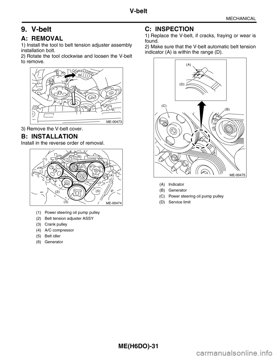
1) Install the tool to belt tension adjuster assembly
installation bolt.
2) Rotate the tool clockwise and loosen the V-belt
to remove.
3) Remove the V-belt cover.
B: INSTALLATION
Install in the reverse order of removal.
C: INSPECTION
1) Replace the V-belt, if cracks, fraying or wear is
found.
2) Make sure that the V-belt automatic belt tension
indicator (A) is within the range (D).
(1) Power steering oil pump pulley
(2) Belt tension adjuster ASSY
(3) Crank pulley
(4) A/C compressor
(5) Belt idler
(6) Generator
ME-00473
(1)(6)
(4)
(5)(2)
(3)ME-00474
(A) Indicator
(B) Generator
(C) Power steering oil pump pulley
(D) Service limit
(B)
(A)
(D)
(C)
ME-00475
Page 1906 of 2453
ME(H6DO)-40
Preparation for Overhaul
MECHANICAL
12.Preparation for Overhaul
A: REMOVAL
1) Remove the engine assembly from the body.
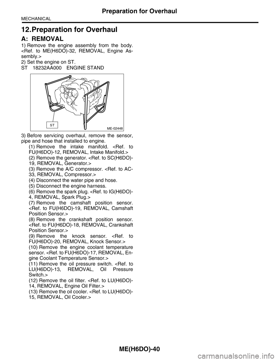
2) Set the engine on ST.
ST 18232AA000 ENGINE STAND
3) Before servicing overhaul, remove the sensor,
pipe and hose that installed to engine.
(1) Remove the intake manifold.
(2) Remove the generator.
(3) Remove the A/C compressor.
(4) Disconnect the water pipe and hose.
(5) Disconnect the engine harness.
(6) Remove the spark plug.
(7) Remove the camshaft position sensor.
(8) Remove the crankshaft position sensor.
(9) Remove the knock sensor.
(10) Remove the engine coolant temperature
sensor.
(11) Remove the oil pressure switch.
Switch.>
(12) Remove the oil filter.
(13) Remove the oil cooler.
STME-02448