Page 1801 of 2453
GD(H6DO)-189
Diagnostic Trouble Code (DTC) Detecting Criteria
GENERAL DESCRIPTION
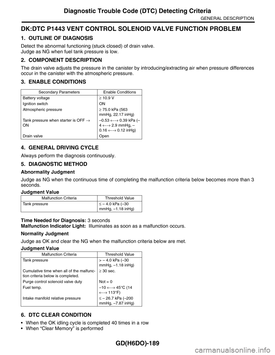
DK:DTC P1443 VENT CONTROL SOLENOID VALVE FUNCTION PROBLEM
1. OUTLINE OF DIAGNOSIS
Detect the abnormal functioning (stuck closed) of drain valve.
Judge as NG when fuel tank pressure is low.
2. COMPONENT DESCRIPTION
The drain valve adjusts the pressure in the canister by introducing/extracting air when pressure differences
occur in the canister with the atmospheric pressure.
3. ENABLE CONDITIONS
4. GENERAL DRIVING CYCLE
Always perform the diagnosis continuously.
5. DIAGNOSTIC METHOD
Abnormality Judgment
Judge as NG when the continuous time of completing the malfunction criteria below becomes more than 3
seconds.
Time Needed for Diagnosis: 3 seconds
Malfunction Indicator Light: Illuminates as soon as a malfunction occurs.
Normality Judgment
Judge as OK and clear the NG when the malfunction criteria below are met.
6. DTC CLEAR CONDITION
•When the OK idling cycle is completed 40 times in a row
•When “Clear Memory” is performed
Secondary Parameters Enable Conditions
Battery voltage≥ 10.9 V
Ignition switch ON
Atmospheric pressure≥ 75.0 kPa (563
mmHg, 22.17 inHg)
Ta n k p r e s s u r e w h e n s t a r t e r i s O F F →
ON
–0.53 ←→ 0.39 kPa (–
4 ←→ 2.9 mmHg, –
0.16 ←→ 0.12 inHg)
Drain valve Open
Judgment Value
Malfunction Criteria Threshold Value
Ta n k p r e s s u r e≤ – 4.0 kPa (–30
mmHg, –1.18 inHg)
Judgment Value
Malfunction Criteria Threshold Value
Ta n k p r e s s u r e > – 4 . 0 k P a ( – 3 0
mmHg, –1.18 inHg)
Cumulative time when all of the malfunc-
tion criteria below is completed.
≥ 30 sec.
Purge control solenoid valve duty Not = 0
Fuel temp. –10 ←→ 45°C (14
←→ 113°F)
Intake manifold relative pressure≤ – 26.7 kPa (–200
mmHg, –7.87 inHg)
Page 1809 of 2453
GD(H6DO)-197
Diagnostic Trouble Code (DTC) Detecting Criteria
GENERAL DESCRIPTION
DY:DTC P2096 POST CATALYST FUEL TRIM SYSTEM TOO LEAN (BANK 1)
1. OUTLINE OF DIAGNOSIS
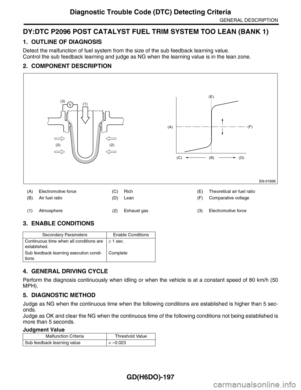
Detect the malfunction of fuel system from the size of the sub feedback learning value.
Control the sub feedback learning and judge as NG when the learning value is in the lean zone.
2. COMPONENT DESCRIPTION
3. ENABLE CONDITIONS
4. GENERAL DRIVING CYCLE
Perform the diagnosis continuously when idling or when the vehicle is at a constant speed of 80 km/h (50
MPH).
5. DIAGNOSTIC METHOD
Judge as NG when the continuous time when the following conditions are established is higher than 5 sec-
onds.
Judge as OK and clear the NG when the continuous time of the following conditions not being established is
more than 5 seconds.
(A) Electromotive force (C) Rich (E) Theoretical air fuel ratio
(B) Air fuel ratio (D) Lean (F) Comparative voltage
(1) Atmosphere (2) Exhaust gas (3) Electromotive force
Secondary Parameters Enable Conditions
Continuous time when all conditions are
established.
≥ 1 sec.
Sub feedback learning execution condi-
tions
Complete
Judgment Value
Malfunction Criteria Threshold Value
Sub feedback learning value < –0.023
EN-01696
(3)V(1)
(2) (2)
(E)
(F)
(C) (B) (D)
(A)
Page 1811 of 2453
GD(H6DO)-199
Diagnostic Trouble Code (DTC) Detecting Criteria
GENERAL DESCRIPTION
DZ:DTC P2097 POST CATALYST FUEL TRIM SYSTEM TOO RICH (BANK 1)
1. OUTLINE OF DIAGNOSIS
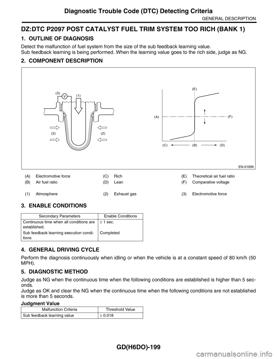
Detect the malfunction of fuel system from the size of the sub feedback learning value.
Sub feedback learning is being performed. When the learning value goes to the rich side, judge as NG.
2. COMPONENT DESCRIPTION
3. ENABLE CONDITIONS
4. GENERAL DRIVING CYCLE
Perform the diagnosis continuously when idling or when the vehicle is at a constant speed of 80 km/h (50
MPH).
5. DIAGNOSTIC METHOD
Judge as NG when the continuous time when the following conditions are established is higher than 5 sec-
onds.
Judge as OK and clear the NG when the continuous time when the following conditions are not established
is more than 5 seconds.
(A) Electromotive force (C) Rich (E) Theoretical air fuel ratio
(B) Air fuel ratio (D) Lean (F) Comparative voltage
(1) Atmosphere (2) Exhaust gas (3) Electromotive force
Secondary Parameters Enable Conditions
Continuous time when all conditions are
established.
≥ 1 sec.
Sub feedback learning execution condi-
tions
Completed
Judgment Value
Malfunction Criteria Threshold Value
Sub feedback learning value≥ 0.018
EN-01696
(3)V(1)
(2) (2)
(E)
(F)
(C) (B) (D)
(A)
Page 1812 of 2453
GD(H6DO)-200
Diagnostic Trouble Code (DTC) Detecting Criteria
GENERAL DESCRIPTION
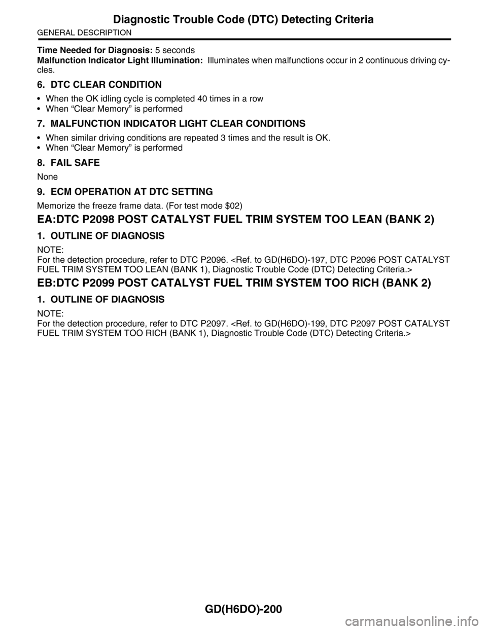
Time Needed for Diagnosis: 5 seconds
Malfunction Indicator Light Illumination: Illuminates when malfunctions occur in 2 continuous driving cy-
cles.
6. DTC CLEAR CONDITION
•When the OK idling cycle is completed 40 times in a row
•When “Clear Memory” is performed
7. MALFUNCTION INDICATOR LIGHT CLEAR CONDITIONS
•When similar driving conditions are repeated 3 times and the result is OK.
•When “Clear Memory” is performed
8. FAIL SAFE
None
9. ECM OPERATION AT DTC SETTING
Memorize the freeze frame data. (For test mode $02)
EA:DTC P2098 POST CATALYST FUEL TRIM SYSTEM TOO LEAN (BANK 2)
1. OUTLINE OF DIAGNOSIS
NOTE:
For the detection procedure, refer to DTC P2096.
FUEL TRIM SYSTEM TOO LEAN (BANK 1), Diagnostic Trouble Code (DTC) Detecting Criteria.>
EB:DTC P2099 POST CATALYST FUEL TRIM SYSTEM TOO RICH (BANK 2)
1. OUTLINE OF DIAGNOSIS
NOTE:
For the detection procedure, refer to DTC P2097.
FUEL TRIM SYSTEM TOO RICH (BANK 1), Diagnostic Trouble Code (DTC) Detecting Criteria.>
Page 1841 of 2453
IG(H6DO)-6
Spark Plug
IGNITION
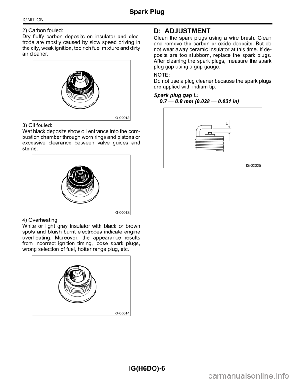
2) Carbon fouled:
Dry fluffy carbon deposits on insulator and elec-
trode are mostly caused by slow speed driving in
the city, weak ignition, too rich fuel mixture and dirty
air cleaner.
3) Oil fouled:
Wet black deposits show oil entrance into the com-
bustion chamber through worn rings and pistons or
excessive clearance between valve guides and
stems.
4) Overheating:
White or light gray insulator with black or brown
spots and bluish burnt electrodes indicate engine
overheating. Moreover, the appearance results
from incorrect ignition timing, loose spark plugs,
wrong selection of fuel, hotter range plug, etc.
D: ADJUSTMENT
Clean the spark plugs using a wire brush. Clean
and remove the carbon or oxide deposits. But do
not wear away ceramic insulator at this time. If de-
posits are too stubborn, replace the spark plugs.
After cleaning the spark plugs, measure the spark
plug gap using a gap gauge.
NOTE:
Do not use a plug cleaner because the spark plugs
are applied with iridium tip.
Spark plug gap L:
0.7 — 0.8 mm (0.028 — 0.031 in)
IG-00012
IG-00013
IG-00014
IG-02035
L
Page 1886 of 2453
ME(H6DO)-20
General Description
MECHANICAL
2. GENERAL TOOL
E: PROCEDURE
It is possible to conduct the following service procedures with engine on vehicle, however, the procedures
described in this section are based on the condition that the engine is removed from vehicle.
•Camshaft
•Cylinder head
18471AA000 FUEL PIPE
ADAPTER
Used for measuring fuel pressure.
42075AG690 FUEL HOSE Used for measuring fuel pressure.
This is a genuine Subaru part.
TOOL NAME REMARKS
Compression gauge Used for measuring compression.
ILLUSTRATION TOOL NUMBER DESCRIPTION REMARKS
Page 1887 of 2453
ME(H6DO)-21
Compression
MECHANICAL
2. Compression
A: INSPECTION
CAUTION:
After warming-up, engine becomes very hot. Be
careful not to burn yourself during measure-
ment.
1) After warming-up the engine, turn the ignition
switch to OFF.
2) Make sure that the battery is fully charged.
3) Release the fuel pressure.
PRESSURE, PROCEDURE, Fuel.>
4) Remove all the spark plugs.
4, REMOVAL, Spark Plug.>
5) Check the starter motor for satisfactory perfor-
mance and operation.
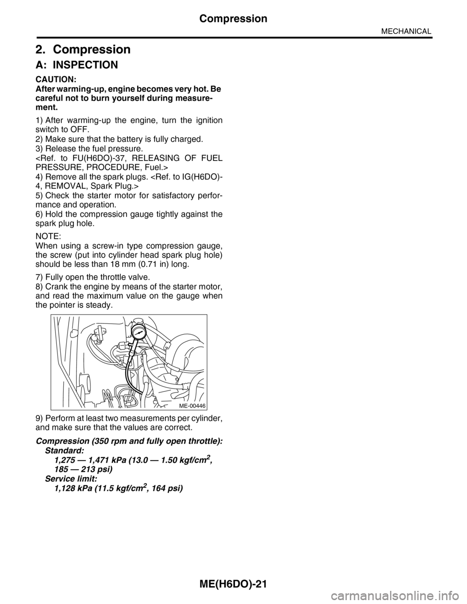
6) Hold the compression gauge tightly against the
spark plug hole.
NOTE:
When using a screw-in type compression gauge,
the screw (put into cylinder head spark plug hole)
should be less than 18 mm (0.71 in) long.
7) Fully open the throttle valve.
8) Crank the engine by means of the starter motor,
and read the maximum value on the gauge when
the pointer is steady.
9) Perform at least two measurements per cylinder,
and make sure that the values are correct.
Compression (350 rpm and fully open throttle):
Standard:
1,275 — 1,471 kPa (13.0 — 1.50 kgf/cm2,
185 — 213 psi)
Service limit:
1,128 kPa (11.5 kgf/cm2, 164 psi)
ME-00446
Page 1892 of 2453
ME(H6DO)-26
Fuel Pressure
MECHANICAL
7. Fuel Pressure
A: INSPECTION
WARNING:
Before removing the fuel pressure gauge, re-
lease the fuel pressure.
1) Release the fuel pressure.
PRESSURE, PROCEDURE, Fuel.>
2) Disconnect the fuel delivery hose and connect
fuel pressure gauge.
(1) Disconnect the fuel delivery hose using the
ST1.
ST1 42099AE000 CONNECTOR REMOVER
(2) Connect the fuel pressure meter using the
ST2 and ST3.
NOTE:
ST2 is a genuine Subaru part.
ST2 42075AG690 FUEL HOSE
ST3 18471AA000 FUEL PIPE ADAPTER
3) Install the fuse of fuel pump to main fuse box.
4) Start the engine.
5) Measure the fuel pressure after warming up the
engine.
Fuel pressure:
Standard: 338 — 348 kPa (3.4 — 3.5 kgf/cm2,
49 — 50.5 psi)
NOTE:
The fuel pressure gauge registers 10 to 20 kPa (0.1
to 0.2 kgf/cm2, 1 to 3 psi) higher than standard val-
ues during high-altitude operations.
(A) ST 2
(B) ST 3
ME-02666
(A)
(B)
FU-01122