2009 SUBARU TRIBECA display
[x] Cancel search: displayPage 1010 of 2453
![SUBARU TRIBECA 2009 1.G Service Workshop Manual VDC(diag)-18
Subaru Select Monitor
VEHICLE DYNAMICS CONTROL (VDC) (DIAGNOSTICS)
3. CLEAR MEMORY MODE
1) On the «Main Menu», select the {2. Each Sys-
tem Check} and press the [YES] key.
2) On SUBARU TRIBECA 2009 1.G Service Workshop Manual VDC(diag)-18
Subaru Select Monitor
VEHICLE DYNAMICS CONTROL (VDC) (DIAGNOSTICS)
3. CLEAR MEMORY MODE
1) On the «Main Menu», select the {2. Each Sys-
tem Check} and press the [YES] key.
2) On](/manual-img/17/7322/w960_7322-1009.png)
VDC(diag)-18
Subaru Select Monitor
VEHICLE DYNAMICS CONTROL (VDC) (DIAGNOSTICS)
3. CLEAR MEMORY MODE
1) On the «Main Menu», select the {2. Each Sys-
tem Check} and press the [YES] key.
2) On the «System Selection Menu» display
screen, select the {Brake Control} and press the
[YES] key.
3) Press the [YES] key after {VDC AWD AT} is dis-
played.
4) On the «Brake Control Diagnosis» display
screen, select the {Memory Clear} and press the
[YES] key.
5) When “Done” and “Turn ignition switch OFF” are
shown on the display screen, turn the Subaru Se-
lect Monitor and ignition switch to OFF.
NOTE:
For details concerning operation procedure, refer
to the “SUBARU SELECT MONITOR OPERATION
MANUAL”.
4. SEQUENCE CONTROL
5. FREEZE FRAME DATA
NOTE:
•Data stored at the time of trouble occurrence is
shown on display.
•Each time trouble occurs, the latest information
is stored in the freeze frame data in memory.
Display Contents to be monitored
Clear memory? DTC deleting function
Display Contents to be monitoredReference tar-
get
ABS
sequence
control
Operate the valve and
pump motor continuously
to perform the ABS
sequence control.
Sequence Con-
trol.>
VDC
sequence
control
Operate the valve and
pump motor continuously
to perform the VDC
sequence control.
Sequence Con-
trol.>
Display Contents to be monitored
IG CounterNumber of times ignition switch turned to
ON is displayed.
DTC The recorded failure code is displayed.
FR Wheel
Speed
Wheel speed detected by front ABS
wheel speed sensor RH is displayed in
km/h or MPH.
FL Wheel Speed
Wheel speed detected by front ABS
wheel speed sensor LH is displayed in
km/h or MPH.
RR Wheel
Speed
Wheel speed detected by rear ABS
wheel speed sensor RH is displayed in
km/h or MPH.
RL Wheel
Speed
Wheel speed detected by rear ABS
wheel speed sensor LH is displayed in
km/h or MPH.
Ve h i c l e S p e e dVe h i c l e s p e e d c a l c u l a t e d b y V D C c o n t r o l
module is displayed.
G Sensor First
ShaftThe sensor value for a 45° angle crossed
2 axis G sensor is displayed.G Sensor Sec-
ond Shaft
Ya w R a t e S e n -
sor
Ve h i c l e a n g u l a r s p e e d d e t e c t e d b y y a w
rate sensor is displayed.
IG power supply
voltage
Vo l t a g e s u p p l i e d t o V D C c o n t r o l m o d u l e
is displayed.
Steering Angle
Sensor
Steering angle detected by steering
angle sensor is displayed.
Pressure sen-
sor output
Brake fluid pressure detected by pres-
sure sensor is displayed.
Engine SpeedEngine speed on malfunction occur-
rence is displayed.
Acceleration
Opening AngleAcceleration opening is displayed.
Gear positionGear position on malfunction occurrence
is displayed.
Steering Angle
Sensor Malfunc-
tion Code
The recorded steering angle sensor fail-
ure code is displayed?
ABS Control
FlagABS control condition is displayed.
EBD Control
FlagEBD control condition is displayed.
Brake Switch Brake ON/OFF is displayed.
TCS Control
FlagTCS control condition is displayed.
VDC Control
FlagVDC control condition is displayed.
E/G Control Flag
Absolute angle
recognition flag
Whether the absolute angle was deter-
mined is displayed.
OFF Switch Sig-
nal
Operation condition of TCS OFF switch
is displayed.
Page 1012 of 2453
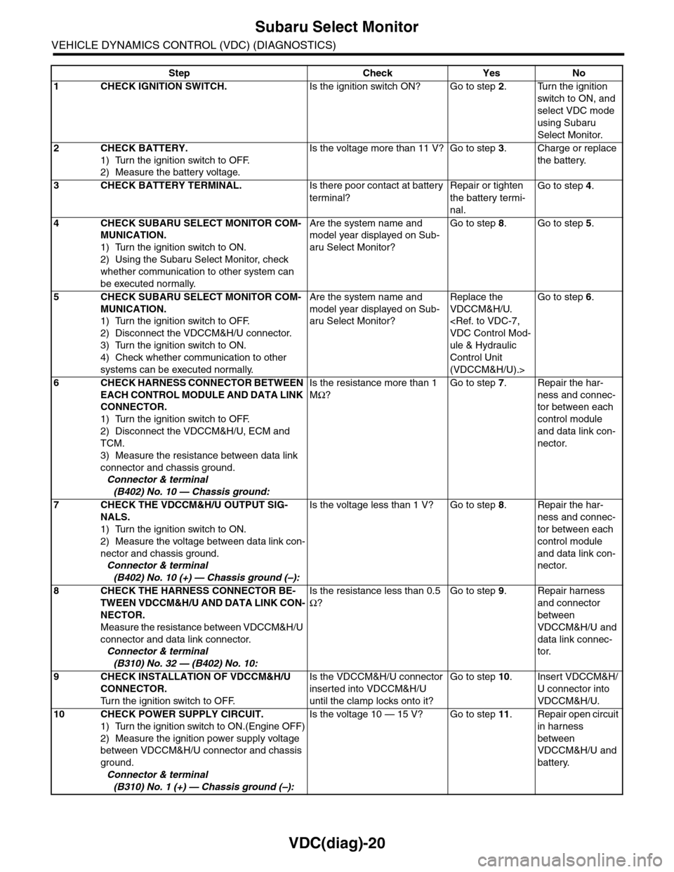
VDC(diag)-20
Subaru Select Monitor
VEHICLE DYNAMICS CONTROL (VDC) (DIAGNOSTICS)
Step Check Yes No
1CHECK IGNITION SWITCH.Is the ignition switch ON? Go to step 2.Turn the ignition
switch to ON, and
select VDC mode
using Subaru
Select Monitor.
2CHECK BATTERY.
1) Turn the ignition switch to OFF.
2) Measure the battery voltage.
Is the voltage more than 11 V? Go to step 3.Charge or replace
the battery.
3CHECK BATTERY TERMINAL.Is there poor contact at battery
terminal?
Repair or tighten
the battery termi-
nal.
Go to step 4.
4CHECK SUBARU SELECT MONITOR COM-
MUNICATION.
1) Turn the ignition switch to ON.
2) Using the Subaru Select Monitor, check
whether communication to other system can
be executed normally.
Are the system name and
model year displayed on Sub-
aru Select Monitor?
Go to step 8.Go to step 5.
5CHECK SUBARU SELECT MONITOR COM-
MUNICATION.
1) Turn the ignition switch to OFF.
2) Disconnect the VDCCM&H/U connector.
3) Turn the ignition switch to ON.
4) Check whether communication to other
systems can be executed normally.
Are the system name and
model year displayed on Sub-
aru Select Monitor?
Replace the
VDCCM&H/U.
ule & Hydraulic
Control Unit
(VDCCM&H/U).>
Go to step 6.
6CHECK HARNESS CONNECTOR BETWEEN
EACH CONTROL MODULE AND DATA LINK
CONNECTOR.
1) Turn the ignition switch to OFF.
2) Disconnect the VDCCM&H/U, ECM and
TCM.
3) Measure the resistance between data link
connector and chassis ground.
Connector & terminal
(B402) No. 10 — Chassis ground:
Is the resistance more than 1
MΩ?
Go to step 7.Repair the har-
ness and connec-
tor between each
control module
and data link con-
nector.
7CHECK THE VDCCM&H/U OUTPUT SIG-
NALS.
1) Turn the ignition switch to ON.
2) Measure the voltage between data link con-
nector and chassis ground.
Connector & terminal
(B402) No. 10 (+) — Chassis ground (–):
Is the voltage less than 1 V? Go to step 8.Repair the har-
ness and connec-
tor between each
control module
and data link con-
nector.
8CHECK THE HARNESS CONNECTOR BE-
TWEEN VDCCM&H/U AND DATA LINK CON-
NECTOR.
Measure the resistance between VDCCM&H/U
connector and data link connector.
Connector & terminal
(B310) No. 32 — (B402) No. 10:
Is the resistance less than 0.5
Ω?
Go to step 9.Repair harness
and connector
between
VDCCM&H/U and
data link connec-
tor.
9CHECK INSTALLATION OF VDCCM&H/U
CONNECTOR.
Tu r n t h e i g n i t i o n s w i t c h t o O F F.
Is the VDCCM&H/U connector
inserted into VDCCM&H/U
until the clamp locks onto it?
Go to step 10.Insert VDCCM&H/
U connector into
VDCCM&H/U.
10 CHECK POWER SUPPLY CIRCUIT.
1) Turn the ignition switch to ON.(Engine OFF)
2) Measure the ignition power supply voltage
between VDCCM&H/U connector and chassis
ground.
Connector & terminal
(B310) No. 1 (+) — Chassis ground (–):
Is the voltage 10 — 15 V? Go to step 11.Repair open circuit
in harness
between
VDCCM&H/U and
battery.
Page 1018 of 2453
VDC(diag)-26
Warning Light Illumination Pattern
VEHICLE DYNAMICS CONTROL (VDC) (DIAGNOSTICS)
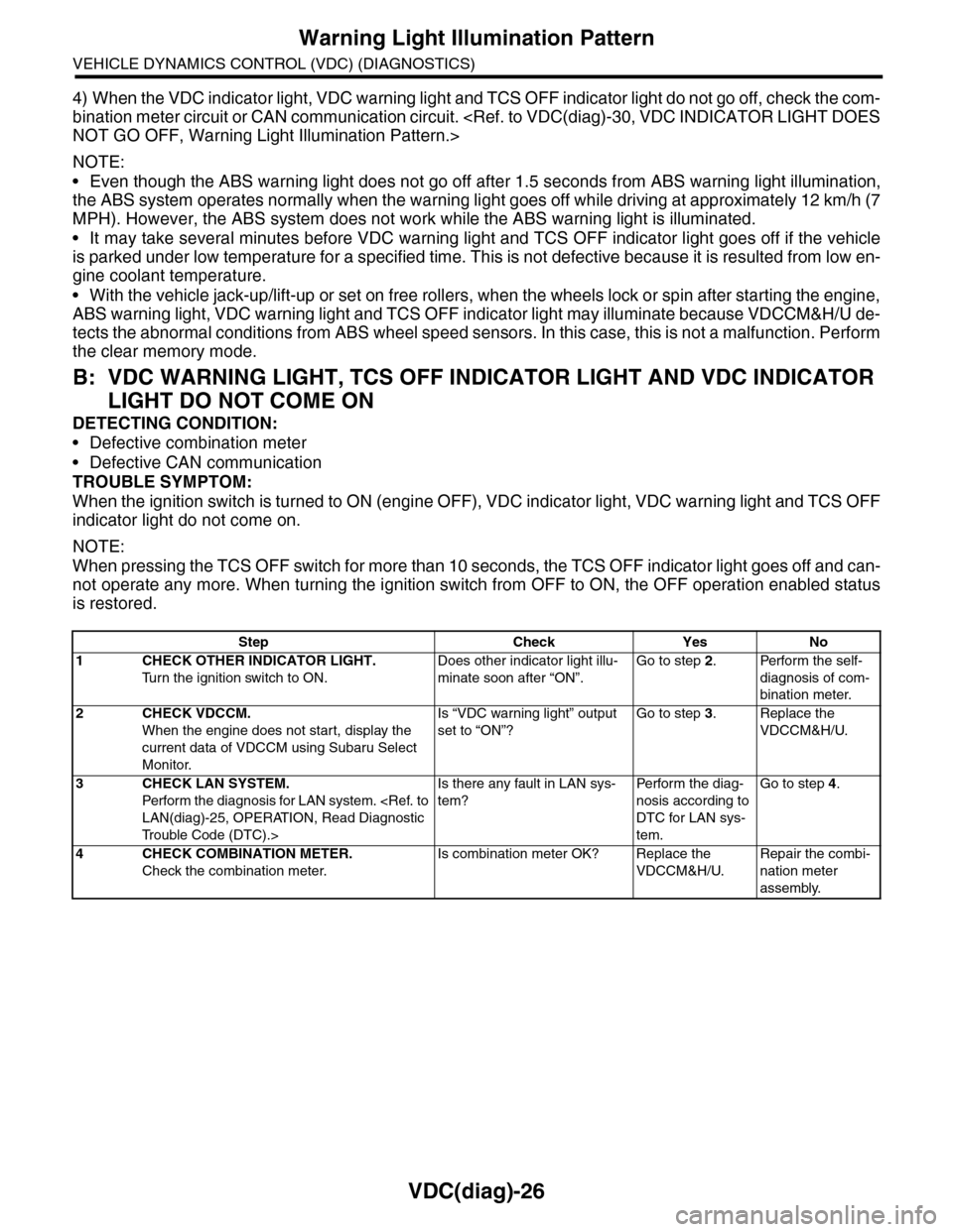
4) When the VDC indicator light, VDC warning light and TCS OFF indicator light do not go off, check the com-
bination meter circuit or CAN communication circuit.
NOTE:
•Even though the ABS warning light does not go off after 1.5 seconds from ABS warning light illumination,
the ABS system operates normally when the warning light goes off while driving at approximately 12 km/h (7
MPH). However, the ABS system does not work while the ABS warning light is illuminated.
•It may take several minutes before VDC warning light and TCS OFF indicator light goes off if the vehicle
is parked under low temperature for a specified time. This is not defective because it is resulted from low en-
gine coolant temperature.
•With the vehicle jack-up/lift-up or set on free rollers, when the wheels lock or spin after starting the engine,
ABS warning light, VDC warning light and TCS OFF indicator light may illuminate because VDCCM&H/U de-
tects the abnormal conditions from ABS wheel speed sensors. In this case, this is not a malfunction. Perform
the clear memory mode.
B: VDC WARNING LIGHT, TCS OFF INDICATOR LIGHT AND VDC INDICATOR
LIGHT DO NOT COME ON
DETECTING CONDITION:
•Defective combination meter
•Defective CAN communication
TROUBLE SYMPTOM:
When the ignition switch is turned to ON (engine OFF), VDC indicator light, VDC warning light and TCS OFF
indicator light do not come on.
NOTE:
When pressing the TCS OFF switch for more than 10 seconds, the TCS OFF indicator light goes off and can-
not operate any more. When turning the ignition switch from OFF to ON, the OFF operation enabled status
is restored.
Step Check Yes No
1CHECK OTHER INDICATOR LIGHT.
Tu r n t h e i g n i t i o n s w i t c h t o O N .
Does other indicator light illu-
minate soon after “ON”.
Go to step 2.Perform the self-
diagnosis of com-
bination meter.
2CHECK VDCCM.
When the engine does not start, display the
current data of VDCCM using Subaru Select
Monitor.
Is “VDC warning light” output
set to “ON”?
Go to step 3.Replace the
VDCCM&H/U.
3CHECK LAN SYSTEM.
Perfor m the diagnosis for LAN system.
Tr o u b l e C o d e ( D T C ) . >
Is there any fault in LAN sys-
tem?
Pe r for m t h e d ia g -
nosis according to
DTC for LAN sys-
tem.
Go to step 4.
4CHECK COMBINATION METER.
Check the combination meter.
Is combination meter OK? Replace the
VDCCM&H/U.
Repair the combi-
nation meter
assembly.
Page 1020 of 2453
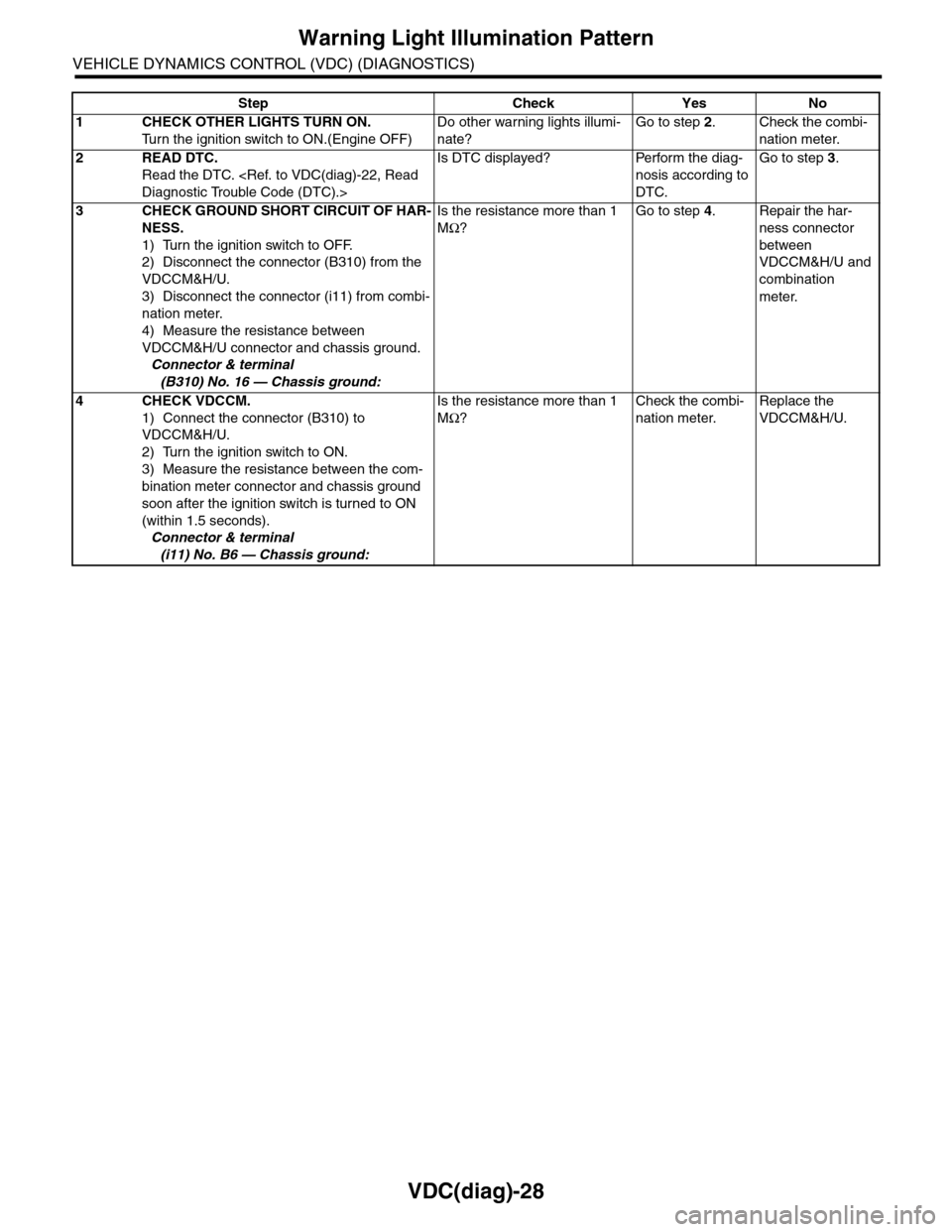
VDC(diag)-28
Warning Light Illumination Pattern
VEHICLE DYNAMICS CONTROL (VDC) (DIAGNOSTICS)
Step Check Yes No
1CHECK OTHER LIGHTS TURN ON.
Tu r n t h e i g n i t i o n s w i t c h t o O N . ( E n g i n e O F F )
Do other warning lights illumi-
nate?
Go to step 2.Check the combi-
nation meter.
2READ DTC.
Read the DTC.
Is DTC displayed? Perform the diag-
nosis according to
DTC.
Go to step 3.
3CHECK GROUND SHORT CIRCUIT OF HAR-
NESS.
1) Turn the ignition switch to OFF.
2) Disconnect the connector (B310) from the
VDCCM&H/U.
3) Disconnect the connector (i11) from combi-
nation meter.
4) Measure the resistance between
VDCCM&H/U connector and chassis ground.
Connector & terminal
(B310) No. 16 — Chassis ground:
Is the resistance more than 1
MΩ?
Go to step 4.Repair the har-
ness connector
between
VDCCM&H/U and
combination
meter.
4CHECK VDCCM.
1) Connect the connector (B310) to
VDCCM&H/U.
2) Turn the ignition switch to ON.
3) Measure the resistance between the com-
bination meter connector and chassis ground
soon after the ignition switch is turned to ON
(within 1.5 seconds).
Connector & terminal
(i11) No. B6 — Chassis ground:
Is the resistance more than 1
MΩ?
Check the combi-
nation meter.
Replace the
VDCCM&H/U.
Page 1022 of 2453
VDC(diag)-30
Warning Light Illumination Pattern
VEHICLE DYNAMICS CONTROL (VDC) (DIAGNOSTICS)
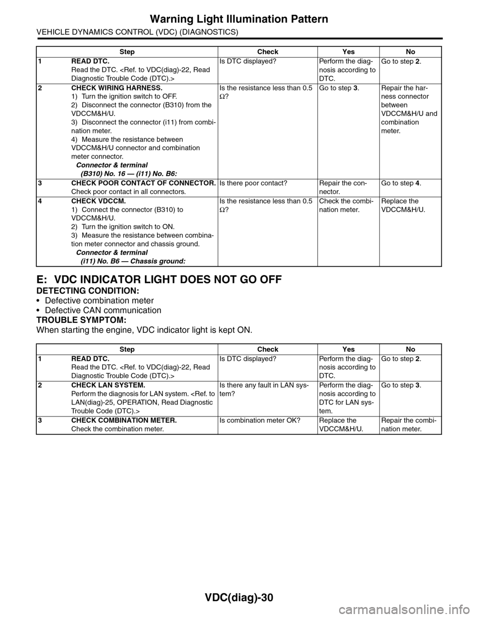
E: VDC INDICATOR LIGHT DOES NOT GO OFF
DETECTING CONDITION:
•Defective combination meter
•Defective CAN communication
TROUBLE SYMPTOM:
When starting the engine, VDC indicator light is kept ON.
Step Check Yes No
1READ DTC.
Read the DTC.
Is DTC displayed? Perform the diag-
nosis according to
DTC.
Go to step 2.
2CHECK WIRING HARNESS.
1) Turn the ignition switch to OFF.
2) Disconnect the connector (B310) from the
VDCCM&H/U.
3) Disconnect the connector (i11) from combi-
nation meter.
4) Measure the resistance between
VDCCM&H/U connector and combination
meter connector.
Connector & terminal
(B310) No. 16 — (i11) No. B6:
Is the resistance less than 0.5
Ω?
Go to step 3.Repair the har-
ness connector
between
VDCCM&H/U and
combination
meter.
3CHECK POOR CONTACT OF CONNECTOR.
Check poor contact in all connectors.
Is there poor contact? Repair the con-
nector.
Go to step 4.
4CHECK VDCCM.
1) Connect the connector (B310) to
VDCCM&H/U.
2) Turn the ignition switch to ON.
3) Measure the resistance between combina-
tion meter connector and chassis ground.
Connector & terminal
(i11) No. B6 — Chassis ground:
Is the resistance less than 0.5
Ω?
Check the combi-
nation meter.
Replace the
VDCCM&H/U.
Step Check Yes No
1READ DTC.
Read the DTC.
Is DTC displayed? Perform the diag-
nosis according to
DTC.
Go to step 2.
2CHECK LAN SYSTEM.
Perfor m the diagnosis for LAN system.
Tr o u b l e C o d e ( D T C ) . >
Is there any fault in LAN sys-
tem?
Pe r for m t h e d ia g -
nosis according to
DTC for LAN sys-
tem.
Go to step 3.
3CHECK COMBINATION METER.
Check the combination meter.
Is combination meter OK? Replace the
VDCCM&H/U.
Repair the combi-
nation meter.
Page 1023 of 2453
VDC(diag)-31
Warning Light Illumination Pattern
VEHICLE DYNAMICS CONTROL (VDC) (DIAGNOSTICS)
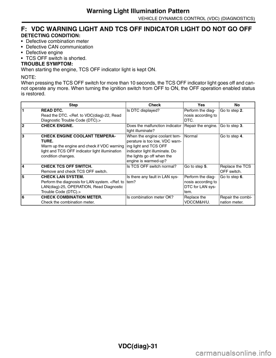
F: VDC WARNING LIGHT AND TCS OFF INDICATOR LIGHT DO NOT GO OFF
DETECTING CONDITION:
•Defective combination meter
•Defective CAN communication
•Defective engine
•TCS OFF switch is shorted.
TROUBLE SYMPTOM:
When starting the engine, TCS OFF indicator light is kept ON.
NOTE:
When pressing the TCS OFF switch for more than 10 seconds, the TCS OFF indicator light goes off and can-
not operate any more. When turning the ignition switch from OFF to ON, the OFF operation enabled status
is restored.
Step Check Yes No
1READ DTC.
Read the DTC.
Is DTC displayed? Perform the diag-
nosis according to
DTC.
Go to step 2.
2CHECK ENGINE.Does the malfunction indicator
light illuminate?
Repair the engine. Go to step 3.
3CHECK ENGINE COOLANT TEMPERA-
TURE.
War m up the engine and check if VDC war ning
light and TCS OFF indicator light illumination
condition changes.
When the engine coolant tem-
perature is too low, VDC warn-
ing light and TCS OFF
indicator light illuminate. Do
the lights go off when the
engine is warmed-up?
Normal Go to step 4.
4CHECK TCS OFF SWITCH.
Remove and check TCS OFF switch.
Is TCS OFF switch normal? Go to step 5.Replace the TCS
OFF switch.
5CHECK LAN SYSTEM.
Perfor m the diagnosis for LAN system.
Tr o u b l e C o d e ( D T C ) . >
Is there any fault in LAN sys-
tem?
Pe r for m t h e d ia g -
nosis according to
DTC for LAN sys-
tem.
Go to step 6.
6CHECK COMBINATION METER.
Check the combination meter.
Is combination meter OK? Replace the
VDCCM&H/U.
Repair the combi-
nation meter.
Page 1025 of 2453
VDC(diag)-33
Warning Light Illumination Pattern
VEHICLE DYNAMICS CONTROL (VDC) (DIAGNOSTICS)
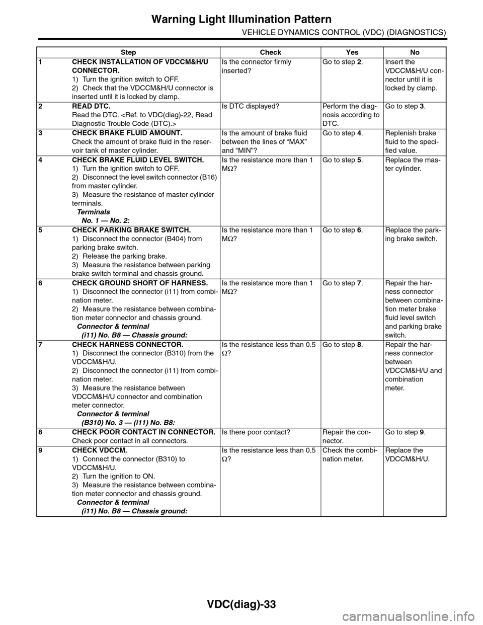
Step Check Yes No
1CHECK INSTALLATION OF VDCCM&H/U
CONNECTOR.
1) Turn the ignition switch to OFF.
2) Check that the VDCCM&H/U connector is
inserted until it is locked by clamp.
Is the connector firmly
inserted?
Go to step 2.Insert the
VDCCM&H/U con-
nector until it is
locked by clamp.
2READ DTC.
Read the DTC.
Is DTC displayed? Perform the diag-
nosis according to
DTC.
Go to step 3.
3CHECK BRAKE FLUID AMOUNT.
Check the amount of brake fluid in the reser-
voir tank of master cylinder.
Is the amount of brake fluid
between the lines of “MAX”
and “MIN”?
Go to step 4.Replenish brake
fluid to the speci-
fied value.
4CHECK BRAKE FLUID LEVEL SWITCH.
1) Turn the ignition switch to OFF.
2) Disconnect the level switch connector (B16)
from master cylinder.
3) Measure the resistance of master cylinder
terminals.
Te r m i n a l s
No. 1 — No. 2:
Is the resistance more than 1
MΩ?
Go to step 5.Replace the mas-
ter cylinder.
5CHECK PARKING BRAKE SWITCH.
1) Disconnect the connector (B404) from
parking brake switch.
2) Release the parking brake.
3) Measure the resistance between parking
brake switch terminal and chassis ground.
Is the resistance more than 1
MΩ?
Go to step 6.Replace the park-
ing brake switch.
6CHECK GROUND SHORT OF HARNESS.
1) Disconnect the connector (i11) from combi-
nation meter.
2) Measure the resistance between combina-
tion meter connector and chassis ground.
Connector & terminal
(i11) No. B8 — Chassis ground:
Is the resistance more than 1
MΩ?
Go to step 7.Repair the har-
ness connector
between combina-
tion meter brake
fluid level switch
and parking brake
switch.
7CHECK HARNESS CONNECTOR.
1) Disconnect the connector (B310) from the
VDCCM&H/U.
2) Disconnect the connector (i11) from combi-
nation meter.
3) Measure the resistance between
VDCCM&H/U connector and combination
meter connector.
Connector & terminal
(B310) No. 3 — (i11) No. B8:
Is the resistance less than 0.5
Ω?
Go to step 8.Repair the har-
ness connector
between
VDCCM&H/U and
combination
meter.
8CHECK POOR CONTACT IN CONNECTOR.
Check poor contact in all connectors.
Is there poor contact? Repair the con-
nector.
Go to step 9.
9CHECK VDCCM.
1) Connect the connector (B310) to
VDCCM&H/U.
2) Turn the ignition to ON.
3) Measure the resistance between combina-
tion meter connector and chassis ground.
Connector & terminal
(i11) No. B8 — Chassis ground:
Is the resistance less than 0.5
Ω?
Check the combi-
nation meter.
Replace the
VDCCM&H/U.
Page 1026 of 2453
VDC(diag)-34
List of Diagnostic Trouble Code (DTC)
VEHICLE DYNAMICS CONTROL (VDC) (DIAGNOSTICS)
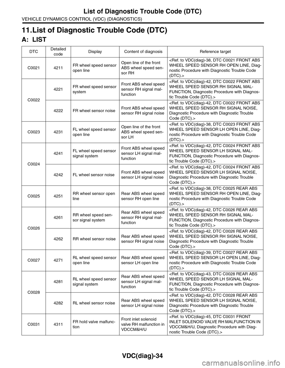
11.List of Diagnostic Trouble Code (DTC)
A: LIST
DTCDetailed
codeDisplay Content of diagnosis Reference target
C0021 4211FR wheel speed sensor
open line
Open line of the front
ABS wheel speed sen-
sor RH
nostic Procedure with Diagnostic Trouble Code
(DTC).>
C0022
4221FR wheel speed sensor
system
Fr o nt A B S w h e el sp e ed
sensor RH signal mal-
function
FUNCTION, Diagnostic Procedure with Diagnos-
tic Trouble Code (DTC).>
4222 FR wheel sensor noiseFr o nt A B S w h e el sp e ed
sensor RH signal noise
Diagnostic Procedure with Diagnostic Trouble
Code (DTC).>
C0023 4231FL wheel speed sensor
open line
Open line of the front
ABS wheel speed sen-
sor LH
nostic Procedure with Diagnostic Trouble Code
(DTC).>
C0024
4241FL wheel speed sensor
signal system
Fr o nt A B S w h e el sp e ed
sensor LH signal mal-
function
FUNCTION, Diagnostic Procedure with Diagnos-
tic Trouble Code (DTC).>
4242 FL wheel sensor noiseFr o nt A B S w h e el sp e ed
sensor LH signal noise
Diagnostic Procedure with Diagnostic Trouble
Code (DTC).>
C0025 4251RR wheel sensor open
line
Rear ABS wheel speed
sensor RH open line
nostic Procedure with Diagnostic Trouble Code
(DTC).>
C0026
4261RR wheel speed sen-
sor signal system
Rear ABS wheel speed
sensor RH signal mal-
function
FUNCTION, Diagnostic Procedure with Diagnos-
tic Trouble Code (DTC).>
4262 RR wheel sensor noiseRear ABS wheel speed
sensor RH signal noise
Diagnostic Procedure with Diagnostic Trouble
Code (DTC).>
C0027 4271RL wheel speed sensor
open line
Rear ABS wheel speed
sensor LH open line
nostic Procedure with Diagnostic Trouble Code
(DTC).>
C0028
4281RL wheel speed sensor
signal system
Rear ABS wheel speed
sensor LH signal mal-
function
FUNCTION, Diagnostic Procedure with Diagnos-
tic Trouble Code (DTC).>
4282 RL wheel sensor noiseRear ABS wheel speed
sensor LH signal noise
Diagnostic Procedure with Diagnostic Trouble
Code (DTC).>
C0031 4311FR hold valve malfunc-
tion
Fr o nt i nl e t s ol e no i d
valve RH malfunction in
VDCCM&H/U
VDCCM&H/U, Diagnostic Procedure with Diag-
nostic Trouble Code (DTC).>