2009 SUBARU TRIBECA wiring
[x] Cancel search: wiringPage 1077 of 2453
VDC(diag)-85
Diagnostic Procedure with Diagnostic Trouble Code (DTC)
VEHICLE DYNAMICS CONTROL (VDC) (DIAGNOSTICS)
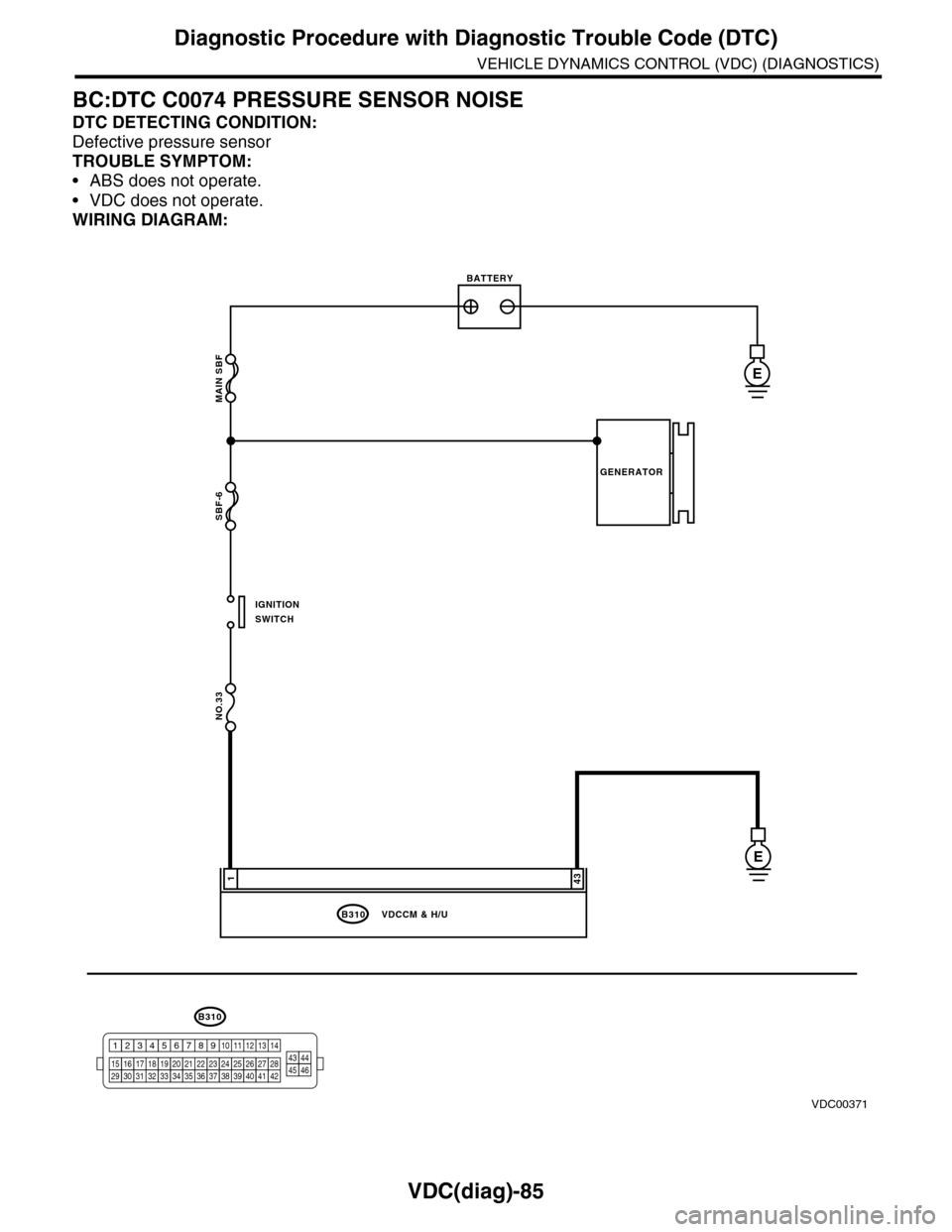
BC:DTC C0074 PRESSURE SENSOR NOISE
DTC DETECTING CONDITION:
Defective pressure sensor
TROUBLE SYMPTOM:
•ABS does not operate.
•VDC does not operate.
WIRING DIAGRAM:
MAIN SBF
SBF-6
NO.33
B310
E
E
431
VDCCM & H/U
BATTERY
GENERATOR
IGNITIONSWITCH
VDC00371
B310
1234
1516171819202122232425262728293031323334353637383940414245464344568910 11 12 13 147
Page 1079 of 2453
VDC(diag)-87
General Diagnostic Table
VEHICLE DYNAMICS CONTROL (VDC) (DIAGNOSTICS)
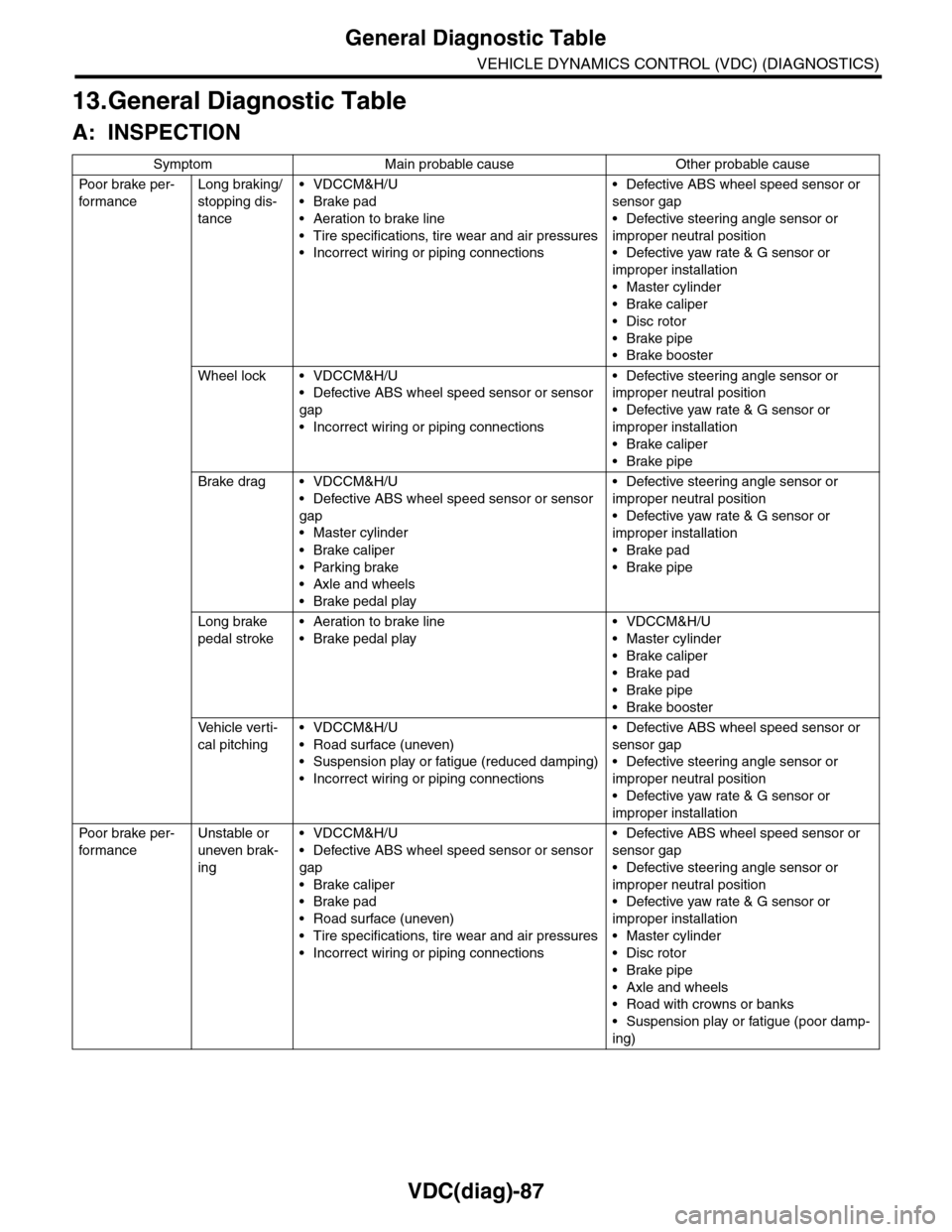
13.General Diagnostic Table
A: INSPECTION
Symptom Main probable cause Other probable cause
Po or b rake pe r -
for mance
Long braking/
stopping dis-
tance
•VDCCM&H/U
•Brake pad
•Aeration to brake line
•Tire specifications, tire wear and air pressures
•Incorrect wiring or piping connections
•Defective ABS wheel speed sensor or
sensor gap
•Defective steering angle sensor or
improper neutral position
•Defective yaw rate & G sensor or
improper installation
•Master cylinder
•Brake caliper
•Disc rotor
•Brake pipe
•Brake booster
Wheel lock • VDCCM&H/U
•Defective ABS wheel speed sensor or sensor
gap
•Incorrect wiring or piping connections
•Defective steering angle sensor or
improper neutral position
•Defective yaw rate & G sensor or
improper installation
•Brake caliper
•Brake pipe
Brake drag • VDCCM&H/U
•Defective ABS wheel speed sensor or sensor
gap
•Master cylinder
•Brake caliper
•Parking brake
•Axle and wheels
•Brake pedal play
•Defective steering angle sensor or
improper neutral position
•Defective yaw rate & G sensor or
improper installation
•Brake pad
•Brake pipe
Long brake
pedal stroke
•Aeration to brake line
•Brake pedal play
•VDCCM&H/U
•Master cylinder
•Brake caliper
•Brake pad
•Brake pipe
•Brake booster
Ve h i c l e v e r t i -
cal pitching
•VDCCM&H/U
•Road surface (uneven)
•Suspension play or fatigue (reduced damping)
•Incorrect wiring or piping connections
•Defective ABS wheel speed sensor or
sensor gap
•Defective steering angle sensor or
improper neutral position
•Defective yaw rate & G sensor or
improper installation
Po or b rake pe r -
for mance
Unstable or
uneven brak-
ing
•VDCCM&H/U
•Defective ABS wheel speed sensor or sensor
gap
•Brake caliper
•Brake pad
•Road surface (uneven)
•Tire specifications, tire wear and air pressures
•Incorrect wiring or piping connections
•Defective ABS wheel speed sensor or
sensor gap
•Defective steering angle sensor or
improper neutral position
•Defective yaw rate & G sensor or
improper installation
•Master cylinder
•Disc rotor
•Brake pipe
•Axle and wheels
•Road with crowns or banks
•Suspension play or fatigue (poor damp-
ing)
Page 1080 of 2453
VDC(diag)-88
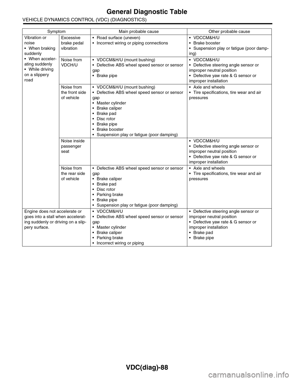
General Diagnostic Table
VEHICLE DYNAMICS CONTROL (VDC) (DIAGNOSTICS)
Vibration or
noise
•When braking
suddenly
•When acceler-
ating suddenly
•While driving
on a slippery
road
Excessive
brake pedal
vibration
•Road surface (uneven)
•Incorrect wiring or piping connections
•VDCCM&H/U
•Brake booster
•Suspension play or fatigue (poor damp-
ing)
Noise from
VDCH/U
•VDCCM&H/U (mount bushing)
•Defective ABS wheel speed sensor or sensor
gap
•Brake pipe
•VDCCM&H/U
•Defective steering angle sensor or
improper neutral position
•Defective yaw rate & G sensor or
improper installation
Noise from
the front side
of vehicle
•VDCCM&H/U (mount bushing)
•Defective ABS wheel speed sensor or sensor
gap
•Master cylinder
•Brake caliper
•Brake pad
•Disc rotor
•Brake pipe
•Brake booster
•Suspension play or fatigue (poor damping)
•Axle and wheels
•Tire specifications, tire wear and air
pressures
Noise inside
passenger
seat
•VDCCM&H/U
•Defective steering angle sensor or
improper neutral position
•Defective yaw rate & G sensor or
improper installation
Noise from
the rear side
of vehicle
•Defective ABS wheel speed sensor or sensor
gap
•Brake caliper
•Brake pad
•Disc rotor
•Parking brake
•Brake pipe
•Suspension play or fatigue (poor damping)
•Axle and wheels
•Tire specifications, tire wear and air
pressures
Engine does not accelerate or
goes into a stall when accelerat-
ing suddenly or driving on a slip-
pery surface.
•VDCCM&H/U
•Defective ABS wheel speed sensor or sensor
gap
•Master cylinder
•Brake caliper
•Parking brake
•Incorrect wiring or piping
•Defective steering angle sensor or
improper neutral position
•Defective yaw rate & G sensor or
improper installation
•Brake pad
•Brake pipe
Symptom Main probable cause Other probable cause
Page 1081 of 2453
VDC(diag)-89
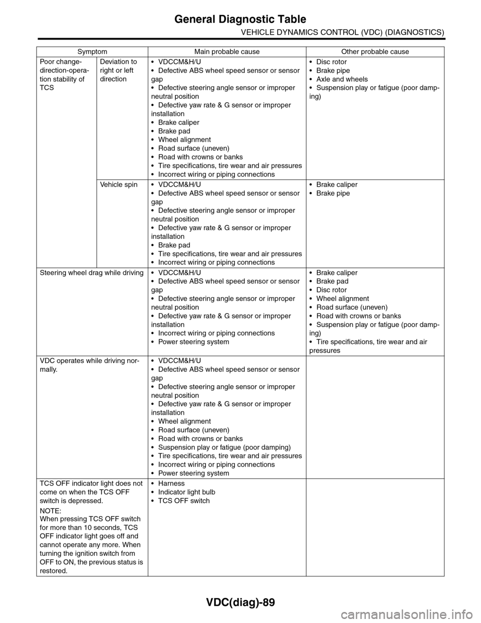
General Diagnostic Table
VEHICLE DYNAMICS CONTROL (VDC) (DIAGNOSTICS)
Po or ch a ng e -
direction-opera-
tion stability of
TCS
Deviation to
right or left
direction
•VDCCM&H/U
•Defective ABS wheel speed sensor or sensor
gap
•Defective steering angle sensor or improper
neutral position
•Defective yaw rate & G sensor or improper
installation
•Brake caliper
•Brake pad
•Wheel alignment
•Road surface (uneven)
•Road with crowns or banks
•Tire specifications, tire wear and air pressures
•Incorrect wiring or piping connections
•Disc rotor
•Brake pipe
•Axle and wheels
•Suspension play or fatigue (poor damp-
ing)
Ve h i c l e s p i n • V D C C M & H / U
•Defective ABS wheel speed sensor or sensor
gap
•Defective steering angle sensor or improper
neutral position
•Defective yaw rate & G sensor or improper
installation
•Brake pad
•Tire specifications, tire wear and air pressures
•Incorrect wiring or piping connections
•Brake caliper
•Brake pipe
Steering wheel drag while driving • VDCCM&H/U
•Defective ABS wheel speed sensor or sensor
gap
•Defective steering angle sensor or improper
neutral position
•Defective yaw rate & G sensor or improper
installation
•Incorrect wiring or piping connections
•Power steering system
•Brake caliper
•Brake pad
•Disc rotor
•Wheel alignment
•Road surface (uneven)
•Road with crowns or banks
•Suspension play or fatigue (poor damp-
ing)
•Tire specifications, tire wear and air
pressures
VDC operates while driving nor-
mally.
•VDCCM&H/U
•Defective ABS wheel speed sensor or sensor
gap
•Defective steering angle sensor or improper
neutral position
•Defective yaw rate & G sensor or improper
installation
•Wheel alignment
•Road surface (uneven)
•Road with crowns or banks
•Suspension play or fatigue (poor damping)
•Tire specifications, tire wear and air pressures
•Incorrect wiring or piping connections
•Power steering system
TCS OFF indicator light does not
come on when the TCS OFF
switch is depressed.
NOTE:When pressing TCS OFF switch
for more than 10 seconds, TCS
OFF indicator light goes off and
cannot operate any more. When
turning the ignition switch from
OFF to ON, the previous status is
restored.
•Harness
•Indicator light bulb
•TCS OFF switch
Symptom Main probable cause Other probable cause
Page 1126 of 2453
CO(H6DO)-7
Radiator Fan System
COOLING
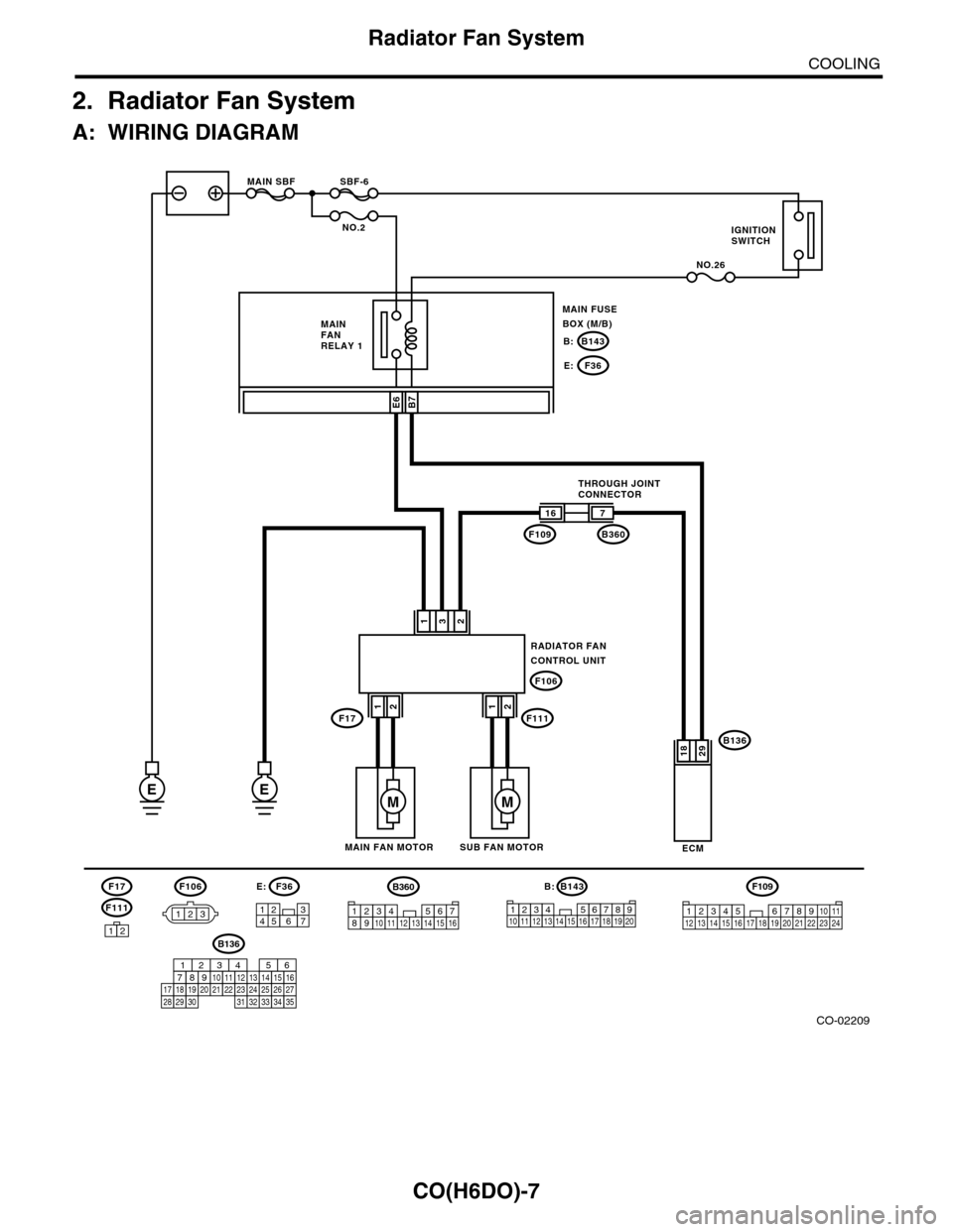
2. Radiator Fan System
A: WIRING DIAGRAM
CO-02209
RADIATOR FANCONTROL UNIT
132
B136
ECM
16
F109
F106
7
B360
2918
F106
123
B7
E
SBF-6MAIN SBF
NO.2
NO.26
B143B:
F36E:
E6
3127456
F36E:B143
123456712131415161718
B:
8191192010
EM
SUB FAN MOTORMAIN FAN MOTOR
THROUGH JOINTCONNECTOR
MAIN FANRELAY 1
MAIN FUSEBOX (M/B)
IGNITIONSWITCH
F17F11112
M
12
F111
F17
12
F109
3412 8910 1112 13 14 15 16 17 18 19 20 21 22 23 24567
B136
16101112131415252430
9871718192028212223293231
123456
2726333435
B360
12345678910111213141516
Page 1166 of 2453
EN(H6DO)(diag)-5
General Description
ENGINE (DIAGNOSTICS)
3. General Description
A: CAUTION
1) Airbag system wiring harness is routed near the
ECM, main relay and fuel pump relay.
CAUTION:
•All airbag system wiring harnesses and con-
nectors are colored yellow. Do not use electri-
cal test equipment on these circuits.
•Be careful not to damage the airbag system
wiring harness when servicing the ECM, TCM,
main relay and fuel pump relay.
2) Never connect the battery in reverse polarity.
•The ECM will be destroyed instantly.
•The fuel injector and other parts will be dam-
aged.
3) Do not disconnect the battery terminals while the
engine is running.
A large counter electromotive force will be generat-
ed in the generator, and this voltage may damage
electronic parts such as ECM etc.
4) Before disconnecting the connectors of each
sensor and ECM, be sure to turn the ignition switch
to OFF. Perform the clear memory mode after con-
necting the connectors.
5) Poor contact has been identified as a primary
cause of this problem. Measure the voltage or re-
sistance of individual sensor or all electrical control
modules using a tapered pin with a diameter of less
than 0.64 mm (0.025 in). Do not insert the pin more
than 5 mm (0.20 in) into the part.
6) Remove the ECM from the located position after
disconnecting two cables on battery.
Otherwise, the ECM may be damaged.
CAUTION:
When replacing the ECM, be careful not to use
the wrong spec. ECM to avoid any damage on
the fuel injection system.
7) Connectors of each sensor in the engine com-
partment and the harness connectors on the en-
gine side and body side are all designed to be
waterproof. Even if the connectors are waterproof,
take care not to allow water to get into them when
washing the vehicle, or when servicing the vehicle
in rainy weather.
8) Use ECM mounting stud bolts as the grounding
point to chassis when measuring voltage and resis-
tance in the passenger compartment.
9) Use the engine ground terminal or engine as-
sembly as the grounding point to chassis when
measuring the voltage and resistance in engine
compartment.
10) Every MFI-related part is a precision part. Do
not drop them.
11) Observe the following cautions when installing
a radio in MFI equipped models.
CAUTION:
•The antenna must be kept as far apart as pos-
sible from control unit. (The ECM is located un-
der the steering column, inside of the
instrument panel lower trim panel.)
•The antenna feeder must be placed as far apart
as possible from the ECM and MFI harness.
•Carefully adjust the antenna for correct
matching.
•When mounting a large power type radio, pay
special attention to the three items mentioned
above.
•Incorrect installation of the radio may affect
the operation of ECM.
12) Release the pressure in the fuel system before
disconnecting the fuel hose. If engine starts during
this operation, run it until it stops.
13) For the model with ABS, the ABS warning light
may illuminate when performing driving test with
jacked-up or lifted-up condition, but this is not a
system malfunction. The reason for this is the
speed difference between the front and rear
wheels. After diagnosis of engine control system,
perform the ABS memory clear procedure of self-
diagnosis function.
B: INSPECTION
Before performing diagnostics, check the following
item which might affect engine problems.
1. BATTERY
1) Measure the battery voltage and specific gravity
of electrolyte.
Standard voltage: 12 V
Specific gravity: Above 1.260
2) Check the condition of the main and other fuses,
and harnesses and connectors. Also check for
proper grounding.
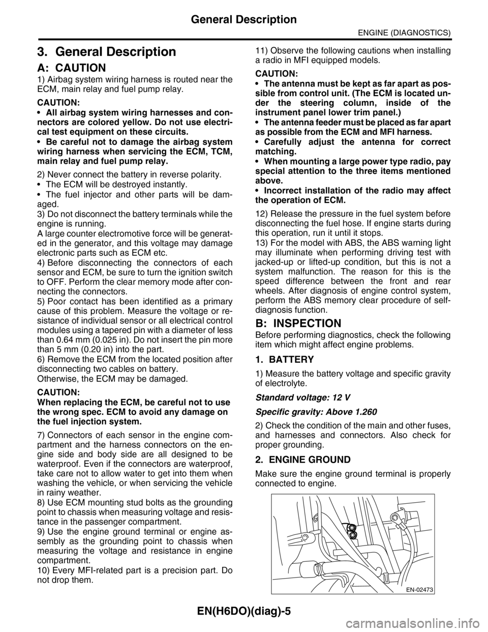
2. ENGINE GROUND
Make sure the engine ground terminal is properly
connected to engine.
EN-02473
Page 1211 of 2453
EN(H6DO)(diag)-50
Malfunction Indicator Light
ENGINE (DIAGNOSTICS)
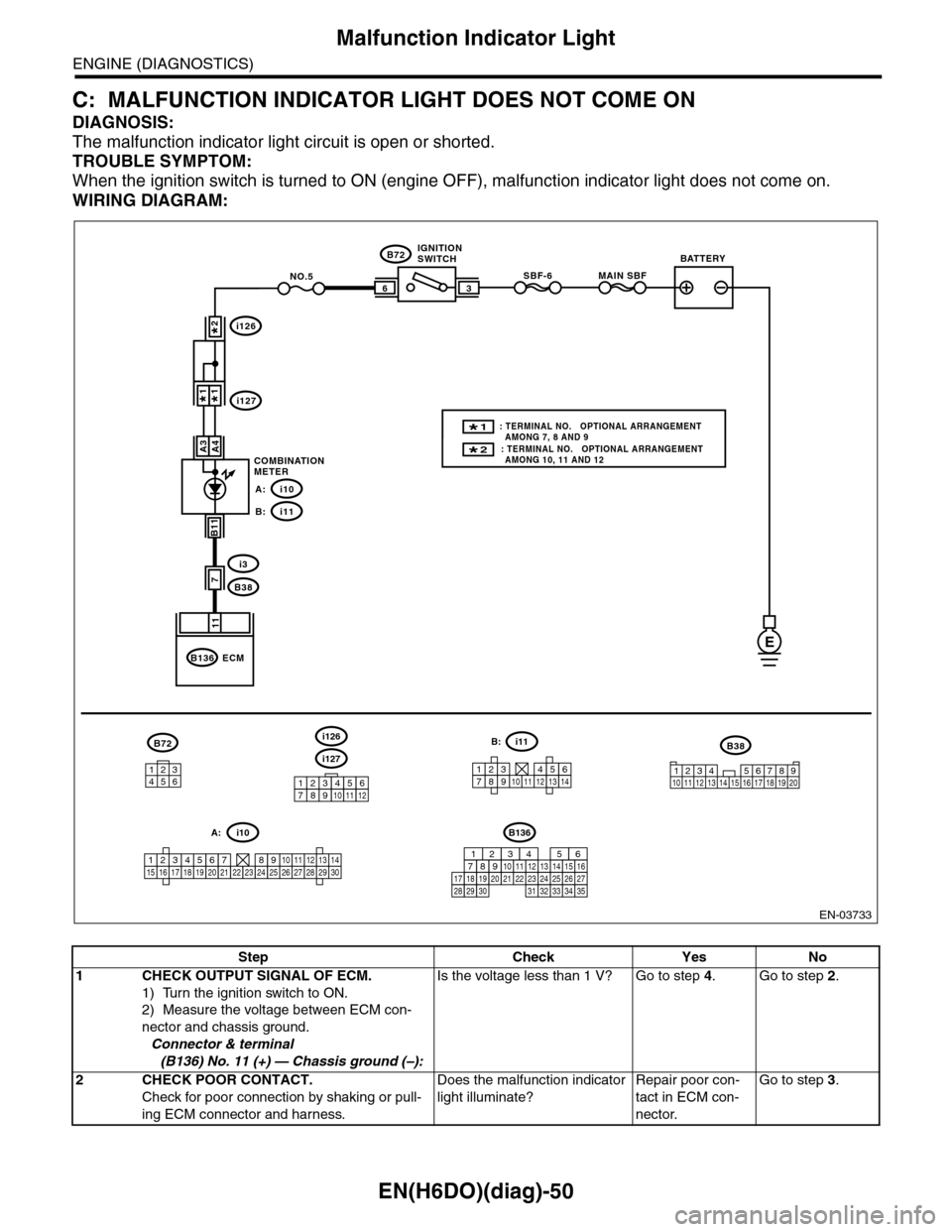
C: MALFUNCTION INDICATOR LIGHT DOES NOT COME ON
DIAGNOSIS:
The malfunction indicator light circuit is open or shorted.
TROUBLE SYMPTOM:
When the ignition switch is turned to ON (engine OFF), malfunction indicator light does not come on.
WIRING DIAGRAM:
EN-03733
3
B72
i3
B38
B136
SBF-66
11
A4
7
MAIN SBFNO.5
B11
E
A3
B72
134562
B38
1234 5678910 11 12 13 14 15 16 17 18 19 20
ECM
COMBINATIONMETER
IGNITIONSWITCHBATTERY
i126
i1271*1*
2*
i10A:
i11B:
i127
i126
123456789101112
1234567891011121314
i11B:
123456789101112131415161718192021222324252627282930
i10A:
2* : TERMINAL NO. OPTIONAL ARRANGEMENT AMONG 10, 11 AND 12
1* : TERMINAL NO. OPTIONAL ARRANGEMENT AMONG 7, 8 AND 9
B136
16101112131415252430
9871718192028212223293231
123456
2726333435
Step Check Yes No
1CHECK OUTPUT SIGNAL OF ECM.
1) Turn the ignition switch to ON.
2) Measure the voltage between ECM con-
nector and chassis ground.
Connector & terminal
(B136) No. 11 (+) — Chassis ground (–):
Is the voltage less than 1 V? Go to step 4.Go to step 2.
2CHECK POOR CONTACT.
Check for poor connection by shaking or pull-
ing ECM connector and harness.
Does the malfunction indicator
light illuminate?
Repair poor con-
tact in ECM con-
nector.
Go to step 3.
Page 1213 of 2453
EN(H6DO)(diag)-52
Malfunction Indicator Light
ENGINE (DIAGNOSTICS)
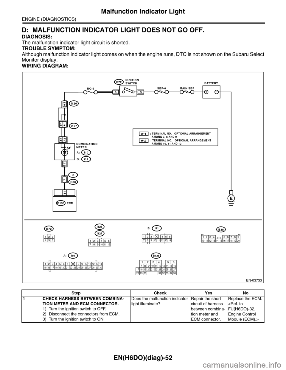
D: MALFUNCTION INDICATOR LIGHT DOES NOT GO OFF.
DIAGNOSIS:
The malfunction indicator light circuit is shorted.
TROUBLE SYMPTOM:
Although malfunction indicator light comes on when the engine runs, DTC is not shown on the Subaru Select
Monitor display.
WIRING DIAGRAM:
EN-03733
3
B72
i3
B38
B136
SBF-66
11
A4
7
MAIN SBFNO.5
B11
E
A3
B72
134562
B38
1234 5678910 11 12 13 14 15 16 17 18 19 20
ECM
COMBINATIONMETER
IGNITIONSWITCHBATTERY
i126
i1271*1*
2*
i10A:
i11B:
i127
i126
123456789101112
1234567891011121314
i11B:
123456789101112131415161718192021222324252627282930
i10A:
2* : TERMINAL NO. OPTIONAL ARRANGEMENT AMONG 10, 11 AND 12
1* : TERMINAL NO. OPTIONAL ARRANGEMENT AMONG 7, 8 AND 9
B136
16101112131415252430
9871718192028212223293231
123456
2726333435
Step Check Yes No
1CHECK HARNESS BETWEEN COMBINA-
TION METER AND ECM CONNECTOR.
1) Turn the ignition switch to OFF.
2) Disconnect the connectors from ECM.
3) Turn the ignition switch to ON.
Does the malfunction indicator
light illuminate?
Repair the short
circuit of harness
between combina-
tion meter and
ECM connector.
Replace the ECM.
Engine Control
Module (ECM).>