Page 1171 of 2453
EN(H6DO)(diag)-10
Electrical Component Location
ENGINE (DIAGNOSTICS)
EN-02479
(1)
EN-02535
(2)
(3)
EN-00895EN-02536
(4)
(5)
(5)
EN-00897EN-02537
(6)
(7)EN-00899EN-02538
(8)
Page 1172 of 2453
EN(H6DO)(diag)-11
Electrical Component Location
ENGINE (DIAGNOSTICS)
(1) Front oxygen (A/F) sensor LH (4) Rear oxygen sensor RH (6) Front catalytic converter RH
(2) Front oxygen (A/F) sensor RH (5) Front catalytic converter LH (7) Rear catalytic converter
(3) Rear oxygen sensor LH
EN-02480
(2)
(1)(3)
(4)(6)
(7)
(5)
EN-02539
(5)
(1)
EN-02540
(2)
(6)
EN-02541
(3)
EN-02542
(4)
(7)
EN-02543
Page 1173 of 2453
EN(H6DO)(diag)-12
Electrical Component Location
ENGINE (DIAGNOSTICS)
(1) Fuel level sensor (3) Fuel tank pressure sensor (4) Fuel sub level sensor
(2) Fuel temperature sensor
EN-03685
(1)
(4)
(2)(3)
EN-03686
(2)
(1)
EN-03687
(3)
EN-03132
(4)
Page 1174 of 2453
EN(H6DO)(diag)-13
Electrical Component Location
ENGINE (DIAGNOSTICS)
•Solenoid valve, actuator, emission control system parts and ignition system parts
(1) Purge control solenoid valve (3) Oil flow control solenoid valve (5)
Va r i a b l e va l v e l i f t d i a g n o s i s o i l
pressure switch(2) Ignition coil (4) Oil switching solenoid valve
EN-03688
(5) (2)
(3)
(2) (1)
(3)
(4) (4)(5)
Page 1175 of 2453
EN(H6DO)(diag)-14
Electrical Component Location
ENGINE (DIAGNOSTICS)
(1) Canister (2) Drain valve
(1)EN-02482(2)EN-02960
(3)
EN-02961
(5)
EN-02962
(4)
EN-03689
(1)
(2)
EN-03690
(1)
(2)
Page 1176 of 2453
EN(H6DO)(diag)-15
Electrical Component Location
ENGINE (DIAGNOSTICS)
(1) Inhibitor switch (4) Fuel pump relay (6) Radiator fan relay
(2) Fuel pump (5) Electronic throttle control relay (7) Starter
(3) Main relay
EN-03691(6)
(3)(2)
(7)
(1)(4) (5)
EN-00178EN-03692
(2)
EN-02544
(3)
(4)
(5)
EN-02489
(6)
EN-02490
(7)
Page 1177 of 2453

EN(H6DO)(diag)-16
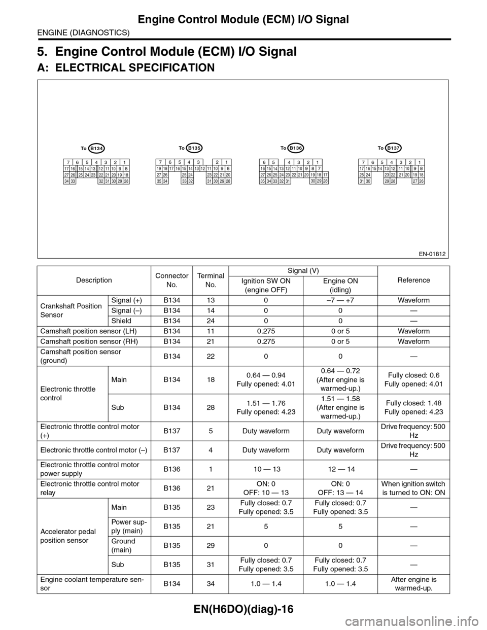
Engine Control Module (ECM) I/O Signal
ENGINE (DIAGNOSTICS)
5. Engine Control Module (ECM) I/O Signal
A: ELECTRICAL SPECIFICATION
DescriptionConnector
No.
Te r m i n a l
No.
Signal (V)
ReferenceIgnition SW ON
(engine OFF)
Engine ON
(idling)
Crankshaft Position
Sensor
Signal (+) B134 13 0 –7 — +7 Waveform
Signal (–) B134 14 0 0 —
Shield B134 24 0 0 —
Camshaft position sensor (LH) B134 11 0.275 0 or 5 Waveform
Camshaft position sensor (RH) B134 21 0.275 0 or 5 Waveform
Camshaft position sensor
(ground)B134 22 0 0 —
Electronic throttle
control
Main B134 180.64 — 0.94
Fully opened: 4.01
0.64 — 0.72
(After engine is
warmed-up.)
Fully closed: 0.6
Fully opened: 4.01
Sub B134 281.51 — 1.76
Fully opened: 4.23
1.51 — 1.58
(After engine is
warmed-up.)
Fully closed: 1.48
Fully opened: 4.23
Electronic throttle control motor
(+)B137 5 Duty waveform Duty waveformDrive frequency: 500
Hz
Electronic throttle control motor (–) B137 4 Duty waveform Duty waveformDrive frequency: 500
Hz
Electronic throttle control motor
power supplyB136 1 10 — 13 12 — 14 —
Electronic throttle control motor
relayB136 21ON: 0
OFF: 10 — 13
ON: 0
OFF: 13 — 14
When ignition switch
is turned to ON: ON
Accelerator pedal
position sensor
Main B135 23Fully closed: 0.7
Fully opened: 3.5
Fully closed: 0.7
Fully opened: 3.5—
Powe r s up -
ply (main)B135 21 5 5 —
Ground
(main)B135 29 0 0 —
Sub B135 31Fully closed: 0.7
Fully opened: 3.5
Fully closed: 0.7
Fully opened: 3.5—
Engine coolant temperature sen-
sorB134 34 1.0 — 1.4 1.0 — 1.4After engine is
warmed-up.
EN-01812
B134
5678219431024 2223251112131415262728
1617181920213334 2932 3031
B136
5678219431024 2223251112131415262728
16171819202133342932303135
B135
5678219431024 2223251112131415262728
16171819202129303132333435
B137
5678219431022231112131415242526
1617181920212728293031
ToToToTo
Page 1178 of 2453

EN(H6DO)(diag)-17
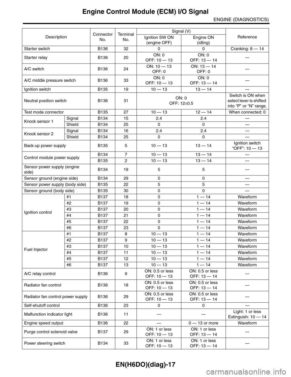
Engine Control Module (ECM) I/O Signal
ENGINE (DIAGNOSTICS)
Starter switch B136 32 0 0 Cranking: 8 — 14
Starter relay B136 20ON: 0
OFF: 10 — 13
ON: 0
OFF: 13 — 14—
A/C switch B136 24ON: 10 — 13
OFF: 0
ON: 13 — 14
OFF: 0—
A/C middle pressure switch B136 33ON: 0
OFF: 10 — 13
ON: 0
OFF: 13 — 14—
Ignition switch B135 19 10 — 13 13 — 14 —
Neutral position switch B136 31ON: 0
OFF: 12±0.5
Switch is ON when
select lever is shifted
into “P” or “N” range.
Te s t m o d e c o n n e c t o r B 1 3 5 2 7 1 0 — 1 3 1 2 — 1 4 W h e n c o n n e c t e d : 0
Knock sensor 1Signal B134 15 2.4 2.4 —
Shield B134 25 0 0 —
Knock sensor 2Signal B134 16 2.4 2.4 —
Shield B134 25 0 0 —
Back-up power supply B135 5 10 — 13 13 — 14Ignition switch
“OFF”: 10 — 13
Control module power supplyB134 7 10 — 13 13 — 14 —
B135 2 10 — 13 13 — 14 —
Sensor power supply (engine
side)B134 19 5 5 —
Sensor ground (engine side) B134 29 0 0 —
Sensor power supply (body side) B135 22 5 5 —
Sensor ground (body side) B135 30 0 0 —
Ignition control
#1 B137 18 0 1 — 14 Waveform
#2 B137 19 0 1 — 14 Waveform
#3 B137 20 0 1 — 14 Waveform
#4 B137 21 0 1 — 14 Waveform
#5 B137 22 0 1 — 14 Waveform
#6 B137 23 0 1 — 14 Waveform
Fuel Injector
#1 B137 8 10 — 13 1 — 14 Waveform
#2 B137 9 10 — 13 1 — 14 Waveform
#3 B137 10 10 — 13 1 — 14 Waveform
#4 B137 11 10 — 13 1 — 14 Waveform
#5 B137 12 10 — 13 1 — 14 Waveform
#6 B137 13 10 — 13 1 — 14 Waveform
A/C relay control B136 9ON: 0.5 or less
OFF: 10 — 13
ON: 0.5 or less
OFF: 13 — 14—
Radiator fan control B136 18ON: 0.5 or less
OFF: 10 — 13
ON: 0.5 or less
OFF: 13 — 14—
Radiator fan control power supply B136 29ON: 0.5 or less
OFF: 10 — 13
ON: 0.5 or less
OFF: 13 — 14—
Self-shutoff control B136 23 0 0 —
Malfunction indicator light B136 11 — —Light: 1 or less
Extinguish: 10 — 14
Engine speed output B136 22 — 0 — 13 or more Waveform
Purge control solenoid valve B137 29ON: 1 or less
OFF: 10 — 13
ON: 1 or less
OFF: 13 — 14—
Pow er s te e r in g sw it c h B 1 3 4 33ON: 1 or less
OFF: 10 — 13
ON: 1 or less
OFF: 13 — 14—
DescriptionConnector
No.
Te r m i n a l
No.
Signal (V)
ReferenceIgnition SW ON
(engine OFF)
Engine ON
(idling)