Page 213 of 2453

ET-28
Rear Entertainment
ENTERTAINMENT
23.Rear Entertainment
A: REMOVAL
1) Disconnect the ground cable from battery.
2) Insert a flat tip screw driver in the section, and
remove the room lamp lens.
3) Remove the bolts, and then remove the monitor
cover.
4) Remove the 4 mounting bolts.
5) Remove the temporary screws and remove the
monitor body.
NOTE:
Always support with one hand to prevent the unit
from falling.
6) Remove the temporary clips from the roof brace.
B: INSTALLATION
1) Attach the temporary clip and temporary screw
to the rear entertainment system body.
NOTE:
When installing a new rear entertainment system, a
clip is supplied on the unit, and this step can be
omitted.
2) Place the hook of the rear entertainment unit on
the roof brace section.
3) Affix the temporary fixture clips on the roof
brace.
4) Tighten the 4 attachment bolts, and connect the
connector.
5) Connect the room lamp connector, attach the
cover and affix with the bolts.
6) Attach the room lamp lens from the outside of
the vehicle and snap into place.
Install in the reverse order of removal.
(A) Cutout
(A) Clip
ET-00188
(A)
ET-00189
(A)
ET-00199
ET-00190
Page 214 of 2453
ET-29
AUX Input Terminal
ENTERTAINMENT
24.AUX Input Terminal
A: REMOVAL
1) Disconnect the ground cable from battery.
2) Remove the quarter trim.
MOVAL, Rear Quarter Trim.>
3) Remove the AUX input terminal from the trim.
B: INSTALLATION
Install in the reverse order of removal.
Page 216 of 2453
ET-31
Rear Accessory Power Supply Socket
ENTERTAINMENT
26.Rear Accessory Power Sup-
ply Socket
A: REMOVAL
1) Disconnect the ground cable from battery.
2) Remove the console box.
MOVAL, Center Console.>
3) Disconnect the harness connector, and remove
the accessory power supply socket.
NOTE:
The socket can be pulled out by unlocking the ac-
cessory socket lock in 2 locations and turning the
socket to the left.
B: INSTALLATION
Install in the reverse order of removal.
NOTE:
Confirm that the accessory socket is locked and
can not be pulled out.
ET-00191
(A)
Page 220 of 2453
ET-16
Tweeter
ENTERTAINMENT
11.Tweeter
A: REMOVAL
1. FRONT
1) Disconnect the ground cable from battery.
2) Remove the front door trim.
MOVAL, Door Trim.>
3) Remove the side deflector duct.
4) Remove the tweeter mounting screws.
5) Remove the tweeter.
2. REAR
1) Disconnect the ground cable from battery.
2) Remove the rear quarter trim.
REMOVAL, Rear Quarter Trim.>
3) Disconnect the connector, and then remove the
tweeter mounting screws.
4) Remove the tweeter.
B: INSTALLATION
Install in the reverse order of removal.
ET-00176
ET-00177
Page 292 of 2453
EI-50
Roof Trim
EXTERIOR/INTERIOR TRIM
23.Roof Trim
A: REMOVAL
1) Disconnect the ground cable from battery.
2) Remove the spot map light.
MOVAL, Spot Map Light.>
3) Remove the room light or rear entertainment
(model with rear entertainment system).
LI-30, REMOVAL, Room Light.>
4) Remove the sun visor.
AL, Sun Visor.>
5) Remove the assist grip.
AL, Assist Grip.>
6) Remove the front pillar upper trim and center pil-
lar upper trim.
Trim.>
7) Remove the rear quarter upper trim.
45, REMOVAL, Rear Quarter Trim.>
8) Remove the sunroof opening trim.
9) Remove the clips and each harness, pull out the
rear center seat belt, and remove the roof trim.
B: INSTALLATION
Install in the reverse order of removal.
EI-00501
EI-01354
Page 563 of 2453
LI-30
Room Light
LIGHTING SYSTEM
28.Room Light
A: REMOVAL
1. MODEL WITHOUT REAR ENTERTAIN-
MENT SYSTEM
1) Disconnect the ground cable from battery.
2) Remove the lens (A) and mounting screws (B).
3) Disconnect the harness connector and remove
the room light.
2. MODEL WITH REAR ENTERTAINMENT
SYSTEM
The room light bulb is integrated into the rear enter-
tainment system as a single unit; therefore, refer to
Rear Entertainment System for the removal proce-
dure.
ment.>
B: INSTALLATION
Install in the reverse order of removal.
C: INSPECTION
1. ROOM LIGHT BULB
1) Visually check the bulb for blow out.
2) Check the bulb specification.
SPECIFICATION, General Description.>
3) If NG, replace the bulb with a new one.
2. ROOM LIGHT SWITCH
Measure the resistance between room light switch
terminals.
LI-00315
(A)
LI-00316(B)
Switch position Terminal No. Standard
OFF — 1 MΩ or more
ON 1 and 3 1.5±0.5 Ω
DOOR 2 and 3 1.5±0.5 Ω
LI-00257
321
Page 2304 of 2453

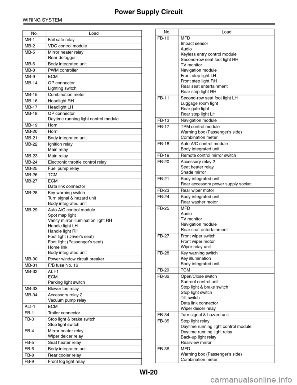
WI-20
Power Supply Circuit
WIRING SYSTEM
No. Load
MB-1 Fail safe relay
MB-2 VDC control module
MB-5 Mirror heater relay
Rear defogger
MB-6 Body integrated unit
MB-8 PWM controller
MB-9 ECM
MB-14 OP connector
Lighting switch
MB-15 Combination meter
MB-16 Headlight RH
MB-17 Headlight LH
MB-18 OP connector
Daytime running light control module
MB-19 Horn
MB-20 Horn
MB-21 Body integrated unit
MB-22 Ignition relay
Main relay
MB-23 Main relay
MB-24 Electronic throttle control relay
MB-25 Fuel pump relay
MB-26 TCM
MB-27 ECM
Data link connector
MB-28 Key warning switch
Tu r n s i g n a l & h a z a r d u n i t
Body integrated unit
MB-29 Auto A/C control module
Spot map light
Va n i t y m i r r o r i l l u m i n a t i o n l i g h t R H
Handle light LH
Handle light RH
Foot light (Driver’s seat)
Foot light (Passenger’s seat)
Home link
Body integrated unit
MB-30 Power window circuit breaker
MB-31 F/B fuse No. 16
MB-32 ALT-1
ECM
Par king light switch
MB-33 Blower fan relay
MB-34 Accessory relay 2
Va c u u m p u m p r e l ay
ALT-1 ECM
FB-1 Trailer connector
FB-3 Stop light & brake switch
Stop light switch
FB-4 Mirror heater relay
Wiper deicer relay
FB-5 Seat heater relay
FB-6 Body integrated unit
FB-8 Rear cooler relay
FB-9 Front fog light relay
FB-10 MFD
Impact sensor
Audio
Keyless entr y control module
Second-row seat foot light RH
TV monitor
Navigation module
Fr o n t s te p li gh t LH
Fr o n t s te p li gh t RH
Rear seat entertainment
Rear step light RH
FB-11 Second-row seat foot light LH
Luggage room light
Rear gate light
Rear step light LH
FB-13 Navigation module
FB-17 TPM control module
War ning box (Passenger’s side)
Combination meter
FB-18 Auto A/C control module
Body integrated unit
FB-19 Remote control mirror switch
FB-20 Accessory relay 2
Seat heater relay
Shade mirror
FB-21 Body integrated unit
Rear accessory power supply socket
FB-23 Rear wiper motor
FB-24 Body integrated unit
Rear washer motor
FB-25 MFD
Audio
TV monitor
Navigation module
Rear seat entertainment
FB-27 Front wiper switch
Fr o n t wi p er mo t or
Wiper relay unit
FB-28 Key warning switch
Key illumination
Body integrated unit
FB-29 TCM
FB-32 Open/Close switch
Sunroof control unit
Stop light & brake switch
Stop light switch
Tilt switch
Data link connector
Wiper deicer relay
FB-34 Turn signal & hazard unit
FB-35 Stop light relay
Daytime running light control module
Daytime running light relay
Back-up light relay
Rearview mirror
FB-36 MFD
War ning box (Passenger’s side)
Combination meter
No. Load
Page 2309 of 2453

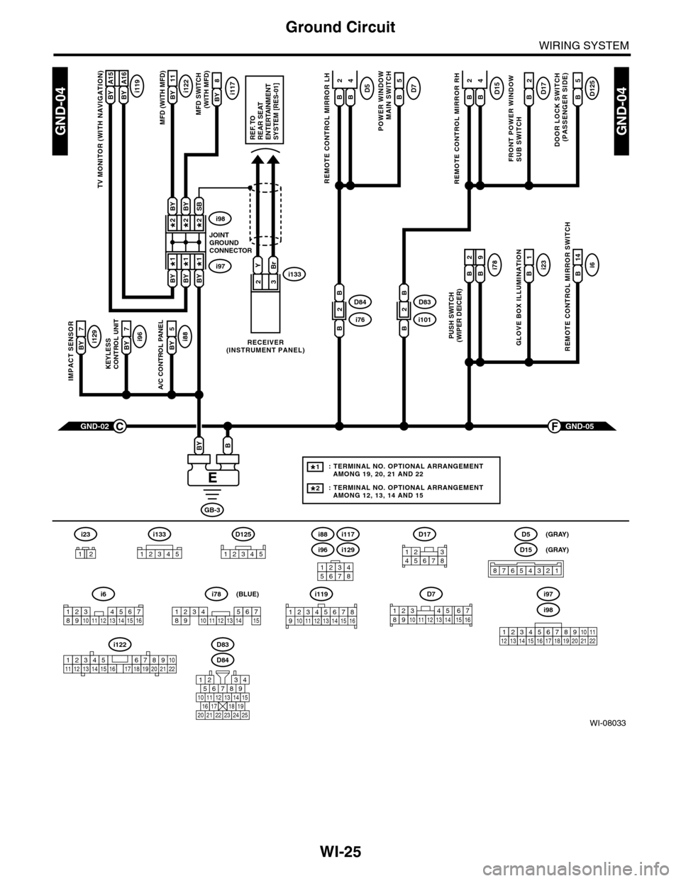
WI-25
Ground Circuit
WIRING SYSTEM
WI-08033
GND-04GND-04
i117BYi122BY 11
8
A/C CONTROL PANEL
i88BY 5
23
GND-05F
KEYLESS CONTROL UNIT
i96BY 7
IMPACT SENSOR
i129BY 7
TV MONITOR (WITH NAVIGATION)
i119BY A15BY A16
GND-02C
GB-3
BBY
D83
MFD (WITH MFD)MFD SWITCH (WITH MFD)
i96
12345678
i6
42
14
REMOTE CONTROL MIRROR SWITCH
i97i133
i98
JOINTGROUNDCONNECTOR
RECEIVER(INSTRUMENT PANEL)
2*2*
1*1*
2*
1*
BYBi231
GLOVE BOX ILLUMINATION
Bi789
PUSH SWITCH(WIPER DEICER)
B
2
BBYBY
SBBYBY
YBr
REF. TOREAR SEATENTERTAINMENT SYSTEM [RES-01]
: TERMINAL NO. OPTIONAL ARRANGEMENT AMONG 19, 20, 21 AND 22
: TERMINAL NO. OPTIONAL ARRANGEMENT AMONG 12, 13, 14 AND 15
1*
2*
D125
5
DOOR LOCK SWITCH(PASSENGER SIDE)
BD17
2
FRONT POWER WINDOW SUB SWITCH
POWER WINDOW
MAIN SWITCH
BD75
BD15
REMOTE CONTROL MIRROR RH
BB
42D5
REMOTE CONTROL MIRROR LH
BB
i1012D83
B
B
i762D84
B
B
D84
i88
i129
i117
567821943
10
2422 23 25
1112131415161718192021
i98
i97
12345678910111213141516171819202122
D7
12345689101112131514716
D17
12345678
D5
D15
87654321
(GRAY)
(GRAY)
i6
12345678910111213141516
i119
123 8910412 13 14 15 1656711
i133
12345
12345678910111213141516171819202122
i122
i78
123456789101112131415
(BLUE)
i23
12
D125
12345