2009 SUBARU TRIBECA Reverse lamp
[x] Cancel search: Reverse lampPage 871 of 2453

FS-23
Front Crossmember
FRONT SUSPENSION
8. Front Crossmember
A: REMOVAL
1) Lift-up the vehicle, and then remove the front
wheels.
2) Remove the front exhaust pipe.
3) Remove the front crossmember support plate.
4) Remove the front stabilizer.
5) Disconnect the tie-rod end from housing.
6) Remove the front arm.
7) Remove the nuts attaching the engine mount
cushion rubber to crossmember.
8) Remove the steering universal joint.
9) Disconnect the power steering hose from steer-
ing gearbox.
10) Lift the engine approx. 10 mm (0.39 in) using
the chain block.
11) Support the crossmember with a jack, remove
the bolts securing crossmember to body, and then
gradually lower the crossmember with steering
gearbox as a unit.
CAUTION:
When removing the crossmember downward,
be careful that the tie-rod end does not interfere
with drive shaft boot.
B: INSTALLATION
1) Install in the reverse order of removal.
NOTE:
•Use a new bolt and self-locking nut. For parts
which are not reusable, refer to “COMPONENT”.
•Always tighten the stabilizer bushing in the state
where the vehicle is at curb weight and the wheels
are in full contact with the ground.
Tightening torque:
Crossmember to body:
95 N·m (9.7 kgf-m, 70.1 ft-lb)
Engine mounting to Crossmember:
85 N·m (8.7 kgf-m, 62.7 ft-lb)
Front arm to Crossmember:
95 N·m (9.7 kgf-m, 70.1 ft-lb)
Front arm to Support plate:
145 N·m (14.8 kgf-m, 106.9 ft-lb)
Support plate to Body:
150 N·m (15.3 kgf-m, 110.6 ft-lb)
Tie–rod end to housing:
27.0 N·m (2.75 kgf-m, 19.9 ft-lb)
After tightening to the specified torque, tighten the
castle nut further but within 60° until the hole in the
ball stud is aligned with a slot in castle nut
Universal joint:
24 N·m (2.4 kgf-m, 17.4 ft-lb)
Stabilizer clamp
25 N·m (2.5 kgf-m, 18.1 ft-lb)
Stabilizer link:
60 N·m (6.1 kgf-m, 44.3 ft-lb)
Power steering hose to Steering gearbox:
15 N·m (1.5 kgf-m, 11 ft-lb)
2) Purge air from the power steering system.
3) Inspect the wheel alignment and adjust if neces-
sary.
C: INSPECTION
Check the crossmember for wear, damage or
cracks, and then repair or replace if faulty.
FS-00209
FS-00119
Page 877 of 2453

PB-6
Parking Brake Cable
PARKING BRAKE
5) Lift-up the vehicle, and then remove the rear
wheels.
6) Remove the rear parking brake cable from the
rear brake.
7) Remove the cable clamp, and remove the park-
ing brake cable from the guide.
8) Remove the cable clamp from rear floor.
9) Remove the cable assembly.
B: INSTALLATION
1) Install in the reverse order of removal.
2) Adjust the parking brake pedal stroke.
Tightening torque:
C: INSPECTION
Check and replace the removed cable if damaged,
rusty or faulty.
1) Check the cable for smooth operation.
2) Check the front parking brake cable for damage
and rust.
3) Check the rear parking brake cable for damage,
bends and cracks.
4) Check the boot for damage, cracks, and corro-
sion.
(1) Guide
PB-00090(1)
PB-00091
Page 941 of 2453

RS-8
Rear Stabilizer
REAR SUSPENSION
3. Rear Stabilizer
A: REMOVAL
1) Lift-up the vehicle, and then remove the rear
wheels.
2) Remove the stabilizer link.
3) Remove the stabilizer link.
B: INSTALLATION
NOTE:
•Use a new flange nut (with WAX).
•Always tighten the stabilizer bushing in the state
where the vehicle is at curb weight and the wheels
are in full contact with the ground.
Install in the reverse order of removal.
Tightening torque:
Stabilizer link
60 N·m (6.1 kgf-m, 44 ft-lb)
Stabilizer clamp
35 N·m (3.6 kgf-m, 25.8 ft-lb)
C: INSPECTION
1) Check the bushing for cracks, fatigue or dam-
age.
2) Check the stabilizer link for damage.
RS-00178
RS-00179
Page 1847 of 2453

IN(H6DO)-5
Air Cleaner Case
INTAKE (INDUCTION)
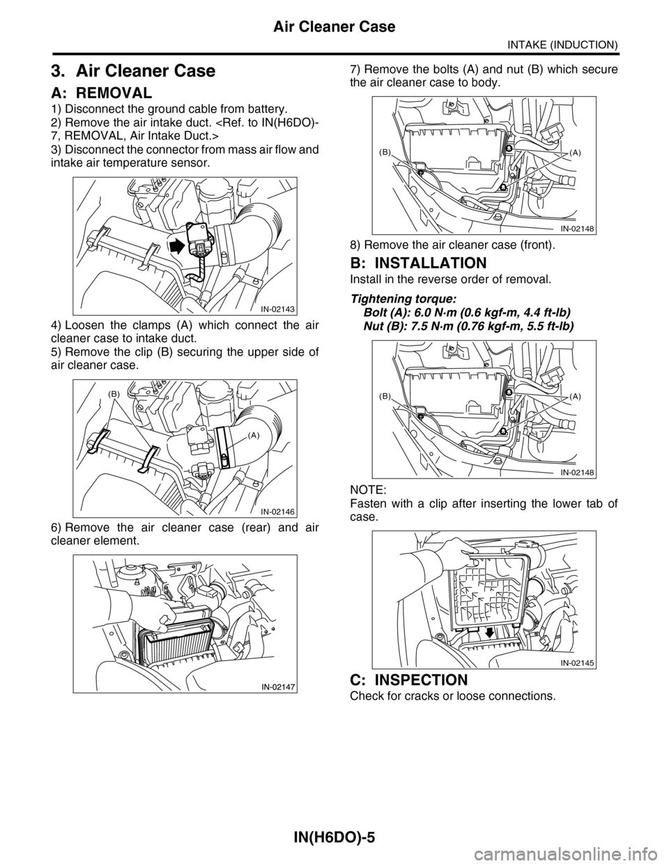
3. Air Cleaner Case
A: REMOVAL
1) Disconnect the ground cable from battery.
2) Remove the air intake duct.
3) Disconnect the connector from mass air flow and
intake air temperature sensor.
4) Loosen the clamps (A) which connect the air
cleaner case to intake duct.
5) Remove the clip (B) securing the upper side of
air cleaner case.
6) Remove the air cleaner case (rear) and air
cleaner element.
7) Remove the bolts (A) and nut (B) which secure
the air cleaner case to body.
8) Remove the air cleaner case (front).
B: INSTALLATION
Install in the reverse order of removal.
Tightening torque:
Bolt (A): 6.0 N·m (0.6 kgf-m, 4.4 ft-lb)
Nut (B): 7.5 N·m (0.76 kgf-m, 5.5 ft-lb)
NOTE:
Fasten with a clip after inserting the lower tab of
case.
C: INSPECTION
Check for cracks or loose connections.
IN-02143
IN-02146
(B)
(A)
IN-02148
(B)(A)
IN-02148
(B)(A)
IN-02145
Page 1848 of 2453

IN(H6DO)-6
Air Intake Chamber
INTAKE (INDUCTION)
4. Air Intake Chamber
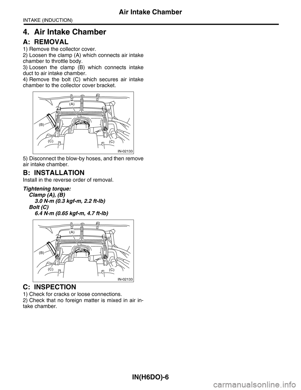
A: REMOVAL
1) Remove the collector cover.
2) Loosen the clamp (A) which connects air intake
chamber to throttle body.
3) Loosen the clamp (B) which connects intake
duct to air intake chamber.
4) Remove the bolt (C) which secures air intake
chamber to the collector cover bracket.
5) Disconnect the blow-by hoses, and then remove
air intake chamber.
B: INSTALLATION
Install in the reverse order of removal.
Tightening torque:
Clamp (A), (B)
3.0 N·m (0.3 kgf-m, 2.2 ft-lb)
Bolt (C)
6.4 N·m (0.65 kgf-m, 4.7 ft-lb)
C: INSPECTION
1) Check for cracks or loose connections.
2) Check that no foreign matter is mixed in air in-
take chamber.
(A)
(C)(C)
(B)
IN-02133
(A)
(C)(C)
(B)
IN-02133
Page 2133 of 2453

5AT(diag)-16
Subaru Select Monitor
AUTOMATIC TRANSMISSION (DIAGNOSTICS)
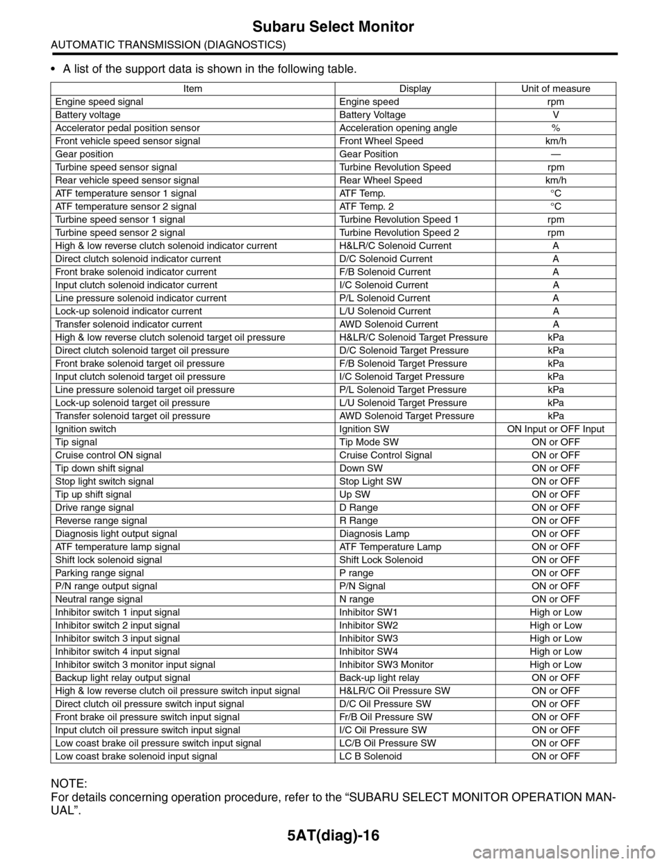
•A list of the support data is shown in the following table.
NOTE:
For details concerning operation procedure, refer to the “SUBARU SELECT MONITOR OPERATION MAN-
UAL”.
Item Display Unit of measure
Engine speed signal Engine speed rpm
Battery voltage Battery Voltage V
Accelerator pedal position sensor Acceleration opening angle %
Fr o nt veh ic l e sp e ed se n so r s ig n al Fr o n t W h ee l S p e ed km/ h
Gear position Gear Position —
Tu r b i n e s p e e d s e n s o r s i g n a l Tu r b i n e R e v o l u t i o n S p e e d r p m
Rear vehicle speed sensor signal Rear Wheel Speed km/h
ATF temperature sensor 1 signal ATF Temp. °C
ATF temperature sensor 2 signal ATF Temp. 2 °C
Tu r b i n e s p e e d s e n s o r 1 s i g n a l Tu r b i n e R e v o l u t i o n S p e e d 1 r p m
Tu r b i n e s p e e d s e n s o r 2 s i g n a l Tu r b i n e R e v o l u t i o n S p e e d 2 r p m
High & low reverse clutch solenoid indicator current H&LR/C Solenoid Current A
Direct clutch solenoid indicator current D/C Solenoid Current A
Fr o nt b rake so l en oi d in di c at o r c u rr e n t F / B S o l en o id Cur r e nt A
Input clutch solenoid indicator current I/C Solenoid Current A
Line pressure solenoid indicator current P/L Solenoid Current A
Lock-up solenoid indicator current L/U Solenoid Current A
Tr a n s f e r s o l e n o i d i n d i c a t o r c u r r e n t A W D S o l e n o i d C u r r e n t A
High & low reverse clutch solenoid target oil pressure H&LR/C Solenoid Target Pressure kPa
Direct clutch solenoid target oil pressure D/C Solenoid Target Pressure kPa
Fr o nt b rake so l en oi d ta r g et o il pr e ss ur e F / B S o l en o id Ta r g et P r es su r e kPa
Input clutch solenoid target oil pressure I/C Solenoid Target Pressure kPa
Line pressure solenoid target oil pressure P/L Solenoid Target Pressure kPa
Lock-up solenoid target oil pressure L/U Solenoid Target Pressure kPa
Tr a n s f e r s o l e n o i d t a r g e t o i l p r e s s u r e A W D S o l e n o i d Ta r g e t P r e s s u r e k P a
Ignition switch Ignition SW ON Input or OFF Input
Tip signal Tip Mode SW ON or OFF
Cruise control ON signal Cruise Control Signal ON or OFF
Tip down shift signal Down SW ON or OFF
Stop light switch signal Stop Light SW ON or OFF
Tip up shift signal Up SW ON or OFF
Drive range signal D Range ON or OFF
Reverse range signal R Range ON or OFF
Diagnosis light output signal Diagnosis Lamp ON or OFF
AT F t e m p e r a t u r e l a m p s i g n a l AT F Te m p e r a t u r e L a m p O N o r O F F
Shift lock solenoid signal Shift Lock Solenoid ON or OFF
Par king range signal P range ON or OFF
P/N range output signal P/N Signal ON or OFF
Neutral range signal N range ON or OFF
Inhibitor switch 1 input signal Inhibitor SW1 High or Low
Inhibitor switch 2 input signal Inhibitor SW2 High or Low
Inhibitor switch 3 input signal Inhibitor SW3 High or Low
Inhibitor switch 4 input signal Inhibitor SW4 High or Low
Inhibitor switch 3 monitor input signal Inhibitor SW3 Monitor High or Low
Backup light relay output signal Back-up light relay ON or OFF
High & low reverse clutch oil pressure switch input signal H&LR/C Oil Pressure SW ON or OFF
Direct clutch oil pressure switch input signal D/C Oil Pressure SW ON or OFF
Fr o nt b rake oi l pr e ss ur e swi tc h i n pu t si gn a l Fr / B Oi l P r e ss ur e S W ON or OF F
Input clutch oil pressure switch input signal I/C Oil Pressure SW ON or OFF
Low coast brake oil pressure switch input signal LC/B Oil Pressure SW ON or OFF
Low coast brake solenoid input signal LC B Solenoid ON or OFF
Page 2277 of 2453
![SUBARU TRIBECA 2009 1.G Service Workshop Manual CS-25
Select Lever
CONTROL SYSTEMS
D: ASSEMBLY
1) Clean all the parts before assembly.
2) Apply grease [Multemp AC-D, and SH-W or
equivalent] to each part. <Ref. to CS-2, AT SE-
LECT LE SUBARU TRIBECA 2009 1.G Service Workshop Manual CS-25
Select Lever
CONTROL SYSTEMS
D: ASSEMBLY
1) Clean all the parts before assembly.
2) Apply grease [Multemp AC-D, and SH-W or
equivalent] to each part. <Ref. to CS-2, AT SE-
LECT LE](/manual-img/17/7322/w960_7322-2276.png)
CS-25
Select Lever
CONTROL SYSTEMS
D: ASSEMBLY
1) Clean all the parts before assembly.
2) Apply grease [Multemp AC-D, and SH-W or
equivalent] to each part.
tion.>
3) Assemble in the reverse order of disassembly.
NOTE:
•Refer to “COMPONENT” for each tightening
torque.
•When pressing in the shift position pin, insert
from the left side of the vehicle.
•Affix the harness of the shift button switch and
the mode change switch at the marked positions.
•Connect the terminals of all switches to the re-
spective connectors.
4) After completing installation, shift the select le-
ver from the “P” range to the “D” range, then check
whether or not the selection indicator in the combi-
nation meter and the select lever position matches.
Also check whether the pointer and position mark
matches, and what the operating force is.
E: INSPECTION
1) Inspect the removed parts by comparing with
new ones for deformation, damage and wear. Re-
pair or replace if defective.
2) Confirm the select lever operating condition be-
fore assembly. Normal if it operates smoothly. CS-00641
(A) Mode change switch (color code: Yellow)
(B) Shift button switch (color code: Brown)
(C) Mode change switch and shift button switch
ground (color code: White)
(D) Shift up switch (color code: Green)
(E) Shift up switch (color code: Gray)
(F) Shift up/down switch ground (color code: Blue)
(G) “P” range switch (wire color: Red)
(H) Shift lock solenoid (color code: Blue)
(I) Shift lock solenoid (color code: Black)
(J) Indicator lamp (color code: Blue)
CS-00642
5432112 11 10 9876
(J)
(J)(F)(E)(D)(A)(B)(C)
(H) (G)(I)