2009 SUBARU TRIBECA Intake manifold
[x] Cancel search: Intake manifoldPage 1192 of 2453
![SUBARU TRIBECA 2009 1.G Service Workshop Manual EN(H6DO)(diag)-31
Subaru Select Monitor
ENGINE (DIAGNOSTICS)
6. READ FREEZE FRAME DATA FOR ENGINE (OBD MODE)
1) On the «Main Menu» display screen, select the {Each System Check} and press the [YES] SUBARU TRIBECA 2009 1.G Service Workshop Manual EN(H6DO)(diag)-31
Subaru Select Monitor
ENGINE (DIAGNOSTICS)
6. READ FREEZE FRAME DATA FOR ENGINE (OBD MODE)
1) On the «Main Menu» display screen, select the {Each System Check} and press the [YES]](/manual-img/17/7322/w960_7322-1191.png)
EN(H6DO)(diag)-31
Subaru Select Monitor
ENGINE (DIAGNOSTICS)
6. READ FREEZE FRAME DATA FOR ENGINE (OBD MODE)
1) On the «Main Menu» display screen, select the {Each System Check} and press the [YES] key.
2) On the «System Selection Menu» display screen, select the {Engine} and press the [YES] key.
3) Press the [YES] key after the information of engine type has been displayed.
4) On the «Engine Diagnosis» display screen, select the {OBD System} and press the [YES] key.
5) On the «OBD Menu» display screen, select the {Freeze Frame Data} and press the [YES] key.
•A list of the support data is shown in the following table.
NOTE:
For detailed operation procedure, refer to the “SUBARU SELECT MONITOR OPERATION MANUAL”.
Description Display Unit of measure
DTC of freeze frame data Freeze frame data DTC
Air fuel ratio control system for bank 1 Fuel system for Bank1 —
Air fuel ratio control system for bank 2 Fuel system for Bank2 —
Engine load data Engine Load %
Engine coolant temperature signal Coolant Temp. °C or °F
Short term fuel trim by front oxygen (A/F) sensor (Bank 1) Short term fuel trim B1 %
Long term fuel trim by front oxygen (A/F) sensor (Bank 1) Long term fuel trim B1 %
Short term fuel trim by front oxygen (A/F) sensor (Bank 2) Short term fuel trim B2 %
Long term fuel trim by front oxygen (A/F) sensor (Bank 2) Long term fuel trim B2 %
Intake manifold absolute pressure signal Mani. Absolute Pressure mmHg, kPa, inHg or psig
Engine speed signal Engine Speed rpm
Ve h i c l e s p e e d s i g n a l Ve h i c l e S p e e d k m / h o r M P H
Ignition timing #1 Ignition timing adv. #1 °
Intake air temperature Intake Air Temp. °C
Amount of intake air Mass Air Flow g/s
Throttle valve angle Throttle Opening Angle %
Oxygen sensor #12 Oxygen sensor #12 V
A/F compensation #12 Short term fuel trim #12 %
Oxygen sensor #22 Oxygen sensor #22 V
A/F compensation #12 Short term fuel trim #22 %
Oxygen sensor #11 Oxygen sensor #11 support
Oxygen sensor #12 Oxygen sensor #12 support
Oxygen sensor #21 Oxygen sensor #21 support
Oxygen sensor #22 Oxygen sensor #22 support
Page 1196 of 2453
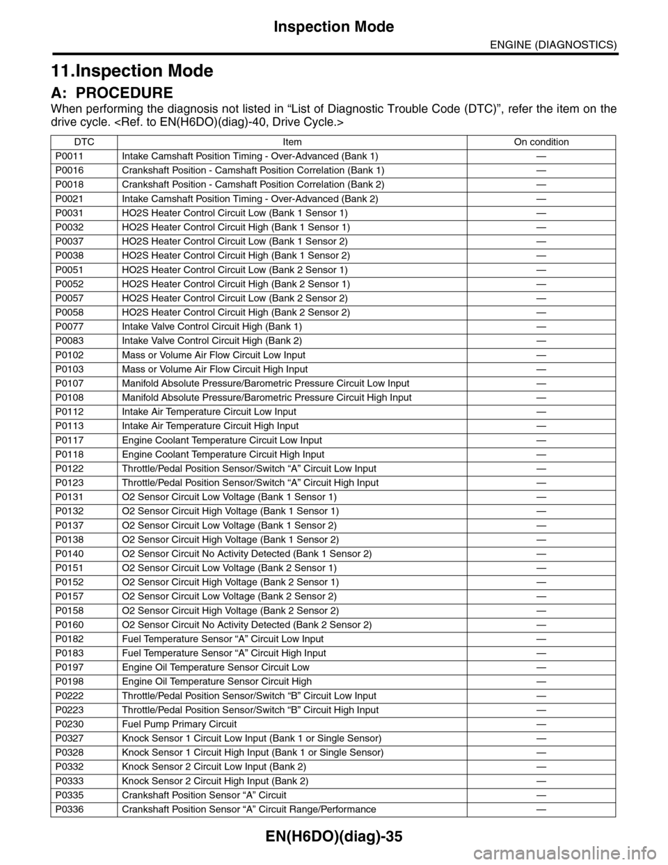
EN(H6DO)(diag)-35
Inspection Mode
ENGINE (DIAGNOSTICS)
11.Inspection Mode
A: PROCEDURE
When performing the diagnosis not listed in “List of Diagnostic Trouble Code (DTC)”, refer the item on the
drive cycle.
DTC Item On condition
P0011 Intake Camshaft Position Timing - Over-Advanced (Bank 1) —
P0016 Crankshaft Position - Camshaft Position Correlation (Bank 1) —
P0018 Crankshaft Position - Camshaft Position Correlation (Bank 2) —
P0021 Intake Camshaft Position Timing - Over-Advanced (Bank 2) —
P0031 HO2S Heater Control Circuit Low (Bank 1 Sensor 1) —
P0032 HO2S Heater Control Circuit High (Bank 1 Sensor 1) —
P0037 HO2S Heater Control Circuit Low (Bank 1 Sensor 2) —
P0038 HO2S Heater Control Circuit High (Bank 1 Sensor 2) —
P0051 HO2S Heater Control Circuit Low (Bank 2 Sensor 1) —
P0052 HO2S Heater Control Circuit High (Bank 2 Sensor 1) —
P0057 HO2S Heater Control Circuit Low (Bank 2 Sensor 2) —
P0058 HO2S Heater Control Circuit High (Bank 2 Sensor 2) —
P0077 Intake Valve Control Circuit High (Bank 1) —
P0083 Intake Valve Control Circuit High (Bank 2) —
P0102 Mass or Volume Air Flow Circuit Low Input —
P0103 Mass or Volume Air Flow Circuit High Input —
P0107 Manifold Absolute Pressure/Barometric Pressure Circuit Low Input —
P0108 Manifold Absolute Pressure/Barometric Pressure Circuit High Input —
P0112 Intake Air Temperature Circuit Low Input —
P0113 Intake Air Temperature Circuit High Input —
P0117 Engine Coolant Temperature Circuit Low Input —
P0118 Engine Coolant Temperature Circuit High Input —
P0122 Throttle/Pedal Position Sensor/Switch “A” Circuit Low Input —
P0123 Throttle/Pedal Position Sensor/Switch “A” Circuit High Input —
P0131 O2 Sensor Circuit Low Voltage (Bank 1 Sensor 1) —
P0132 O2 Sensor Circuit High Voltage (Bank 1 Sensor 1) —
P0137 O2 Sensor Circuit Low Voltage (Bank 1 Sensor 2) —
P0138 O2 Sensor Circuit High Voltage (Bank 1 Sensor 2) —
P0140 O2 Sensor Circuit No Activity Detected (Bank 1 Sensor 2) —
P0151 O2 Sensor Circuit Low Voltage (Bank 2 Sensor 1) —
P0152 O2 Sensor Circuit High Voltage (Bank 2 Sensor 1) —
P0157 O2 Sensor Circuit Low Voltage (Bank 2 Sensor 2) —
P0158 O2 Sensor Circuit High Voltage (Bank 2 Sensor 2) —
P0160 O2 Sensor Circuit No Activity Detected (Bank 2 Sensor 2) —
P0182 Fuel Temperature Sensor “A” Circuit Low Input —
P0183 Fuel Temperature Sensor “A” Circuit High Input —
P0197 Engine Oil Temperature Sensor Circuit Low —
P0198 Engine Oil Temperature Sensor Circuit High —
P0222 Throttle/Pedal Position Sensor/Switch “B” Circuit Low Input —
P0223 Throttle/Pedal Position Sensor/Switch “B” Circuit High Input —
P0230 Fuel Pump Primary Circuit —
P0327 Knock Sensor 1 Circuit Low Input (Bank 1 or Single Sensor) —
P0328 Knock Sensor 1 Circuit High Input (Bank 1 or Single Sensor) —
P0332 Knock Sensor 2 Circuit Low Input (Bank 2) —
P0333 Knock Sensor 2 Circuit High Input (Bank 2) —
P0335 Crankshaft Position Sensor “A” Circuit —
P0336 Crankshaft Position Sensor “A” Circuit Range/Performance —
Page 1231 of 2453
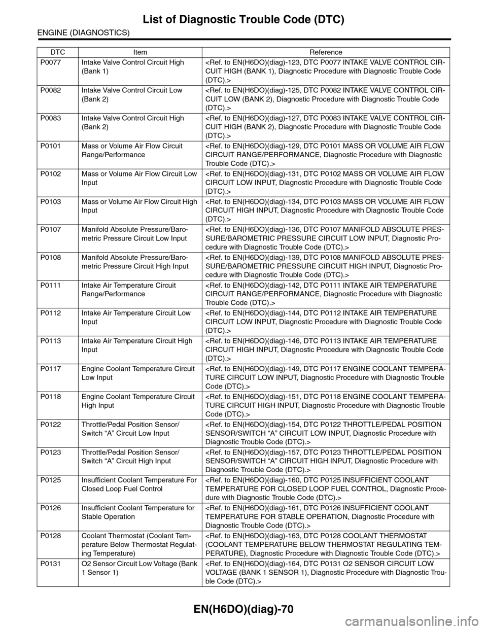
EN(H6DO)(diag)-70
List of Diagnostic Trouble Code (DTC)
ENGINE (DIAGNOSTICS)
P0077 Intake Valve Control Circuit High
(Bank 1)
(DTC).>
P0082 Intake Valve Control Circuit Low
(Bank 2)
(DTC).>
P0083 Intake Valve Control Circuit High
(Bank 2)
(DTC).>
P0101 Mass or Volume Air Flow Circuit
Range/Performance
Tr o u b l e C o d e ( D T C ) . >
P0102 Mass or Volume Air Flow Circuit Low
Input
(DTC).>
P0103 Mass or Volume Air Flow Circuit High
Input
(DTC).>
P0107 Manifold Absolute Pressure/Baro-
metric Pressure Circuit Low Input
cedure with Diagnostic Trouble Code (DTC).>
P0108 Manifold Absolute Pressure/Baro-
metric Pressure Circuit High Input
cedure with Diagnostic Trouble Code (DTC).>
P0111 Intake Air Temperature Circuit
Range/Performance
Tr o u b l e C o d e ( D T C ) . >
P0112 Intake Air Temperature Circuit Low
Input
(DTC).>
P0113 Intake Air Temperature Circuit High
Input
(DTC).>
P0117 Engine Coolant Temperature Circuit
Low Input
Code (DTC).>
P0118 Engine Coolant Temperature Circuit
High Input
Code (DTC).>
P0122 Throttle/Pedal Position Sensor/
Switch “A” Circuit Low Input
Diagnostic Trouble Code (DTC).>
P0123 Throttle/Pedal Position Sensor/
Switch “A” Circuit High Input
Diagnostic Trouble Code (DTC).>
P0125 Insufficient Coolant Temperature For
Closed Loop Fuel Control
dure with Diagnostic Trouble Code (DTC).>
P0126 Insufficient Coolant Temperature for
Stable Operation
Diagnostic Trouble Code (DTC).>
P0128 Coolant Thermostat (Coolant Tem-
perature Below Thermostat Regulat-
ing Temperature)
PERATURE), Diagnostic Procedure with Diagnostic Trouble Code (DTC).>
P0131 O2 Sensor Circuit Low Voltage (Bank
1 Sensor 1)
ble Code (DTC).>
DTC Item Reference
Page 1298 of 2453
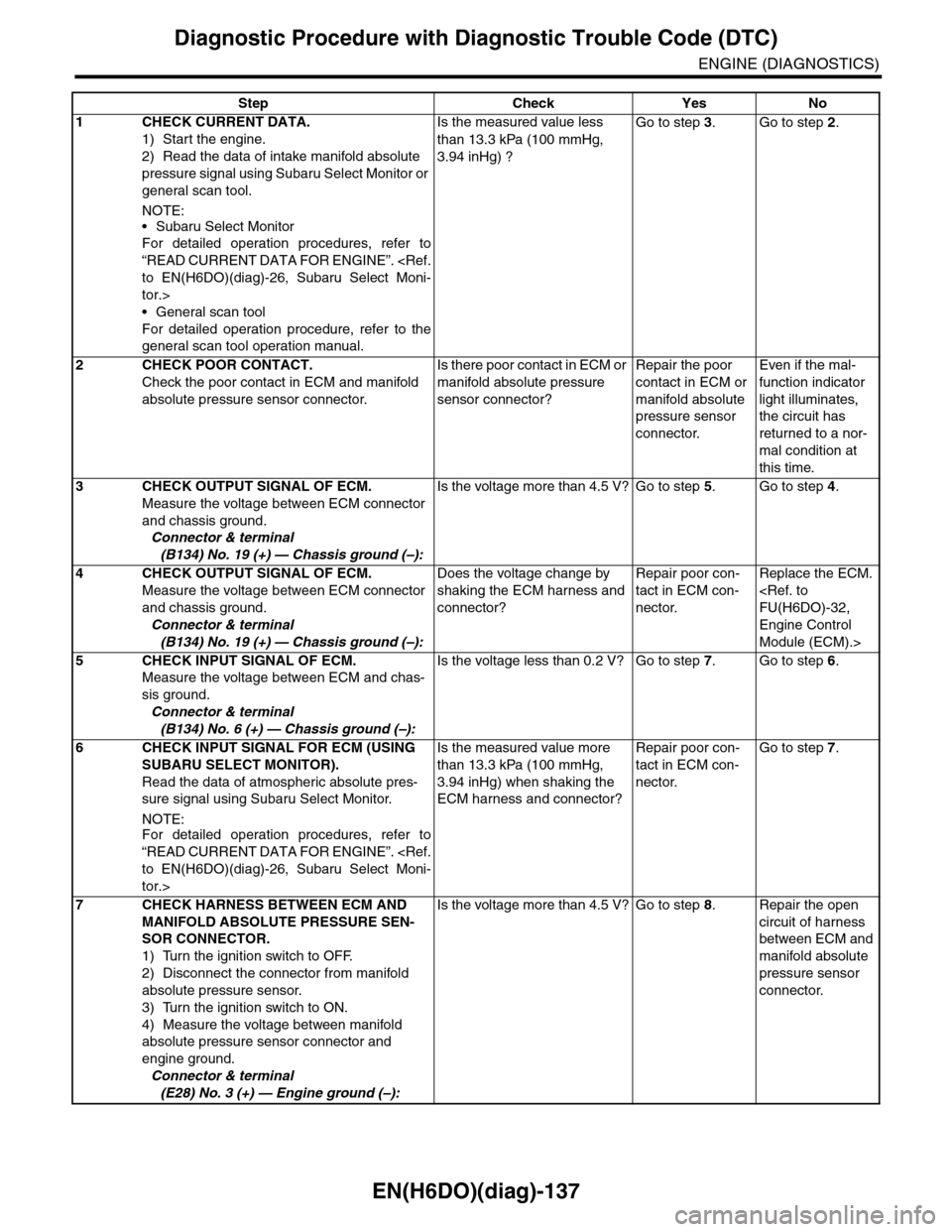
EN(H6DO)(diag)-137
Diagnostic Procedure with Diagnostic Trouble Code (DTC)
ENGINE (DIAGNOSTICS)
Step Check Yes No
1CHECK CURRENT DATA.
1) Start the engine.
2) Read the data of intake manifold absolute
pressure signal using Subaru Select Monitor or
general scan tool.
NOTE:
•Subaru Select Monitor
For detailed operation procedures, refer to
“READ CURRENT DATA FOR ENGINE”.
tor.>
•General scan tool
For detailed operation procedure, refer to the
general scan tool operation manual.
Is the measured value less
than 13.3 kPa (100 mmHg,
3.94 inHg) ?
Go to step 3.Go to step 2.
2CHECK POOR CONTACT.
Check the poor contact in ECM and manifold
absolute pressure sensor connector.
Is there poor contact in ECM or
manifold absolute pressure
sensor connector?
Repair the poor
contact in ECM or
manifold absolute
pressure sensor
connector.
Even if the mal-
function indicator
light illuminates,
the circuit has
returned to a nor-
mal condition at
this time.
3CHECK OUTPUT SIGNAL OF ECM.
Measure the voltage between ECM connector
and chassis ground.
Connector & terminal
(B134) No. 19 (+) — Chassis ground (–):
Is the voltage more than 4.5 V? Go to step 5.Go to step 4.
4CHECK OUTPUT SIGNAL OF ECM.
Measure the voltage between ECM connector
and chassis ground.
Connector & terminal
(B134) No. 19 (+) — Chassis ground (–):
Does the voltage change by
shaking the ECM harness and
connector?
Repair poor con-
tact in ECM con-
nector.
Replace the ECM.
Engine Control
Module (ECM).>
5CHECK INPUT SIGNAL OF ECM.
Measure the voltage between ECM and chas-
sis ground.
Connector & terminal
(B134) No. 6 (+) — Chassis ground (–):
Is the voltage less than 0.2 V? Go to step 7.Go to step 6.
6CHECK INPUT SIGNAL FOR ECM (USING
SUBARU SELECT MONITOR).
Read the data of atmospheric absolute pres-
sure signal using Subaru Select Monitor.
NOTE:For detailed operation procedures, refer to
“READ CURRENT DATA FOR ENGINE”.
tor.>
Is the measured value more
than 13.3 kPa (100 mmHg,
3.94 inHg) when shaking the
ECM harness and connector?
Repair poor con-
tact in ECM con-
nector.
Go to step 7.
7CHECK HARNESS BETWEEN ECM AND
MANIFOLD ABSOLUTE PRESSURE SEN-
SOR CONNECTOR.
1) Turn the ignition switch to OFF.
2) Disconnect the connector from manifold
absolute pressure sensor.
3) Turn the ignition switch to ON.
4) Measure the voltage between manifold
absolute pressure sensor connector and
engine ground.
Connector & terminal
(E28) No. 3 (+) — Engine ground (–):
Is the voltage more than 4.5 V? Go to step 8.Repair the open
circuit of harness
between ECM and
manifold absolute
pressure sensor
connector.
Page 1458 of 2453
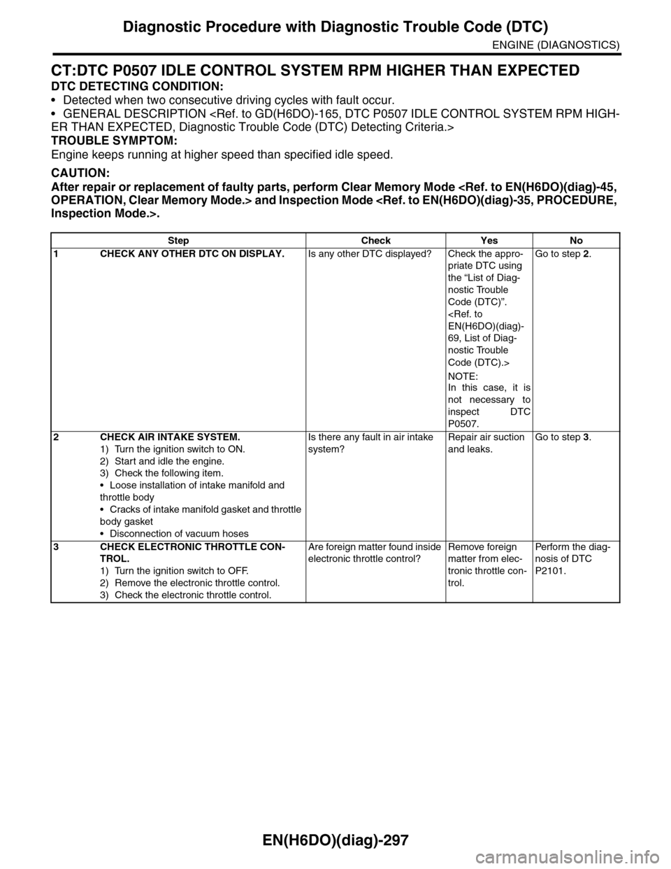
EN(H6DO)(diag)-297
Diagnostic Procedure with Diagnostic Trouble Code (DTC)
ENGINE (DIAGNOSTICS)
CT:DTC P0507 IDLE CONTROL SYSTEM RPM HIGHER THAN EXPECTED
DTC DETECTING CONDITION:
•Detected when two consecutive driving cycles with fault occur.
•GENERAL DESCRIPTION
TROUBLE SYMPTOM:
Engine keeps running at higher speed than specified idle speed.
CAUTION:
After repair or replacement of faulty parts, perform Clear Memory Mode
Step Check Yes No
1CHECK ANY OTHER DTC ON DISPLAY.Is any other DTC displayed? Check the appro-
priate DTC using
the “List of Diag-
nostic Trouble
Code (DTC)”.
69, List of Diag-
nostic Trouble
Code (DTC).>
NOTE:In this case, it is
not necessary to
inspect DTC
P0507.
Go to step 2.
2CHECK AIR INTAKE SYSTEM.
1) Turn the ignition switch to ON.
2) Start and idle the engine.
3) Check the following item.
•Loose installation of intake manifold and
throttle body
•Cracks of intake manifold gasket and throttle
body gasket
•Disconnection of vacuum hoses
Is there any fault in air intake
system?
Repair air suction
and leaks.
Go to step 3.
3CHECK ELECTRONIC THROTTLE CON-
TROL.
1) Turn the ignition switch to OFF.
2) Remove the electronic throttle control.
3) Check the electronic throttle control.
Are foreign matter found inside
electronic throttle control?
Remove foreign
matter from elec-
tronic throttle con-
trol.
Per fo r m th e di ag -
nosis of DTC
P2101.
Page 1461 of 2453
EN(H6DO)(diag)-300
Diagnostic Procedure with Diagnostic Trouble Code (DTC)
ENGINE (DIAGNOSTICS)
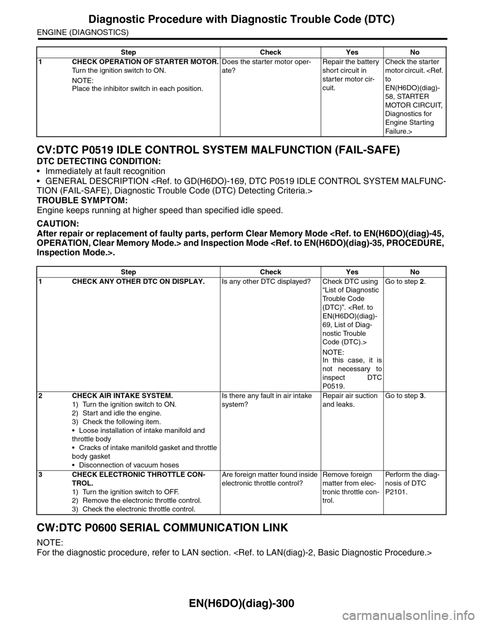
CV:DTC P0519 IDLE CONTROL SYSTEM MALFUNCTION (FAIL-SAFE)
DTC DETECTING CONDITION:
•Immediately at fault recognition
•GENERAL DESCRIPTION
TROUBLE SYMPTOM:
Engine keeps running at higher speed than specified idle speed.
CAUTION:
After repair or replacement of faulty parts, perform Clear Memory Mode
CW:DTC P0600 SERIAL COMMUNICATION LINK
NOTE:
For the diagnostic procedure, refer to LAN section.
Step Check Yes No
1CHECK OPERATION OF STARTER MOTOR.
Tu r n t h e i g n i t i o n s w i t c h t o O N .
NOTE:
Place the inhibitor switch in each position.
Does the starter motor oper-
ate?
Repair the battery
short circuit in
starter motor cir-
cuit.
Check the starter
motor circuit.
EN(H6DO)(diag)-
58, STARTER
MOTOR CIRCUIT,
Diagnostics for
Engine Starting
Fai lu r e.>
Step Check Yes No
1CHECK ANY OTHER DTC ON DISPLAY.Is any other DTC displayed? Check DTC using
“List of Diagnostic
Tr o u b l e C o d e
(DTC)”.
69, List of Diag-
nostic Trouble
Code (DTC).>
NOTE:In this case, it is
not necessary to
inspect DTC
P0519.
Go to step 2.
2CHECK AIR INTAKE SYSTEM.
1) Turn the ignition switch to ON.
2) Start and idle the engine.
3) Check the following item.
•Loose installation of intake manifold and
throttle body
•Cracks of intake manifold gasket and throttle
body gasket
•Disconnection of vacuum hoses
Is there any fault in air intake
system?
Repair air suction
and leaks.
Go to step 3.
3CHECK ELECTRONIC THROTTLE CON-
TROL.
1) Turn the ignition switch to OFF.
2) Remove the electronic throttle control.
3) Check the electronic throttle control.
Are foreign matter found inside
electronic throttle control?
Remove foreign
matter from elec-
tronic throttle con-
trol.
Per fo r m th e di ag -
nosis of DTC
P2101.
Page 1553 of 2453
EN(H6DO)(diag)-392
General Diagnostic Table
ENGINE (DIAGNOSTICS)
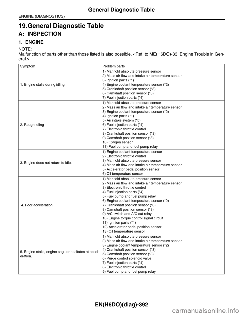
19.General Diagnostic Table
A: INSPECTION
1. ENGINE
NOTE:
Malfunction of parts other than those listed is also possible.
Symptom Problem parts
1. Engine stalls during idling.
1) Manifold absolute pressure sensor
2) Mass air flow and intake air temperature sensor
3) Ignition parts (*1)
4) Engine coolant temperature sensor (*2)
5) Crankshaft position sensor (*3)
6) Camshaft position sensor (*3)
7) Fuel injection parts (*4)
2. Rough idling
1) Manifold absolute pressure sensor
2) Mass air flow and intake air temperature sensor
3) Engine coolant temperature sensor (*2)
4) Ignition parts (*1)
5) Air intake system (*5)
6) Fuel injection parts (*4)
7) Electronic throttle control
8) Crankshaft position sensor (*3)
9) Camshaft position sensor (*3)
10) Oxygen sensor
11) Fuel pump and fuel pump relay
3. Engine does not return to idle.
1) Engine coolant temperature sensor
2) Electronic throttle control
3) Manifold absolute pressure sensor
4) Mass air flow and intake air temperature sensor
5) Accelerator pedal position sensor
6) Oil temperature sensor
4. Poor acceleration
1) Manifold absolute pressure sensor
2) Mass air flow and intake air temperature sensor
3) Electronic throttle control
4) Fuel injection parts (*4)
5) Fuel pump and fuel pump relay
6) Engine coolant temperature sensor (*2)
7) Crankshaft position sensor (*3)
8) Camshaft position sensor (*3)
9) A/C switch and A/C cut relay
10) Engine torque control signal circuit
11) Ignition parts (*1)
12) Accelerator pedal position sensor
13) Oil temperature sensor
5. Engine stalls, engine sags or hesitates at accel-
eration.
1) Manifold absolute pressure sensor
2) Mass air flow and intake air temperature sensor
3) Engine coolant temperature sensor (*2)
4) Crankshaft position sensor (*3)
5) Camshaft position sensor (*3)
6) Purge control solenoid valve
7) Fuel injection parts (*4)
8) Electronic throttle control
9) Fuel pump and fuel pump relay
Page 1554 of 2453
EN(H6DO)(diag)-393
General Diagnostic Table
ENGINE (DIAGNOSTICS)
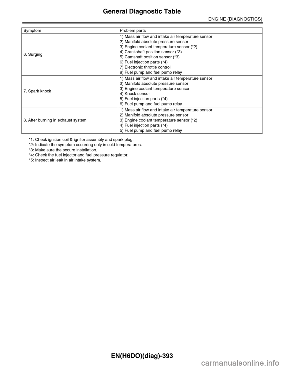
*1: Check ignition coil & ignitor assembly and spark plug.
*2: Indicate the symptom occurring only in cold temperatures.
*3: Make sure the secure installation.
*4: Check the fuel injector and fuel pressure regulator.
*5: Inspect air leak in air intake system.
6. Surging
1) Mass air flow and intake air temperature sensor
2) Manifold absolute pressure sensor
3) Engine coolant temperature sensor (*2)
4) Crankshaft position sensor (*3)
5) Camshaft position sensor (*3)
6) Fuel injection parts (*4)
7) Electronic throttle control
8) Fuel pump and fuel pump relay
7. Spark knock
1) Mass air flow and intake air temperature sensor
2) Manifold absolute pressure sensor
3) Engine coolant temperature sensor
4) Knock sensor
5) Fuel injection parts (*4)
6) Fuel pump and fuel pump relay
8. After burning in exhaust system
1) Mass air flow and intake air temperature sensor
2) Manifold absolute pressure sensor
3) Engine coolant temperature sensor (*2)
4) Fuel injection parts (*4)
5) Fuel pump and fuel pump relay
Symptom Problem parts