Page 1581 of 2453
FU(H6DO)-20
Knock Sensor
FUEL INJECTION (FUEL SYSTEMS)
7. Knock Sensor
A: REMOVAL
1) Remove the collector cover.
2) Disconnect the ground cable from battery.
3) Remove the intake manifold.
fold.>
4) Disconnect the knock sensor connector.
5) Remove the knock sensor from cylinder block.
B: INSTALLATION
1) Install the knock sensor to cylinder block.
Tightening torque:
25 N·m (2.5 kgf-m, 18 ft-lb)
NOTE:
For the knock sensor installation angle, refer to the
figure below.
2) Connect the knock sensor connector.
3) Install the intake manifold.
13, INSTALLATION, Intake Manifold.>
4) Connect the battery ground cable to the battery.
5) Install the collector cover.
(A) Front side of vehicle
FU-00577
45˚30˚10˚
(A)FU-00578
Page 1583 of 2453
FU(H6DO)-22
Manifold Absolute Pressure Sensor
FUEL INJECTION (FUEL SYSTEMS)
9. Manifold Absolute Pressure
Sensor
A: REMOVAL
1) Remove the collector cover.
2) Disconnect the ground cable from battery.
3) Disconnect the connector from manifold abso-
lute pressure sensor (A), and remove the filter as-
sembly (B) from intake manifold.
4) Remove the manifold absolute pressure sensor
from intake manifold.
B: INSTALLATION
Install in the reverse order of removal.
Tightening torque:
6.4 N·m (0.65 kgf-m, 4.7 ft-lb)
FU-02131
(B)(A)
Page 1585 of 2453
FU(H6DO)-24
Fuel Injector
FUEL INJECTION (FUEL SYSTEMS)
11.Fuel Injector
A: REMOVAL
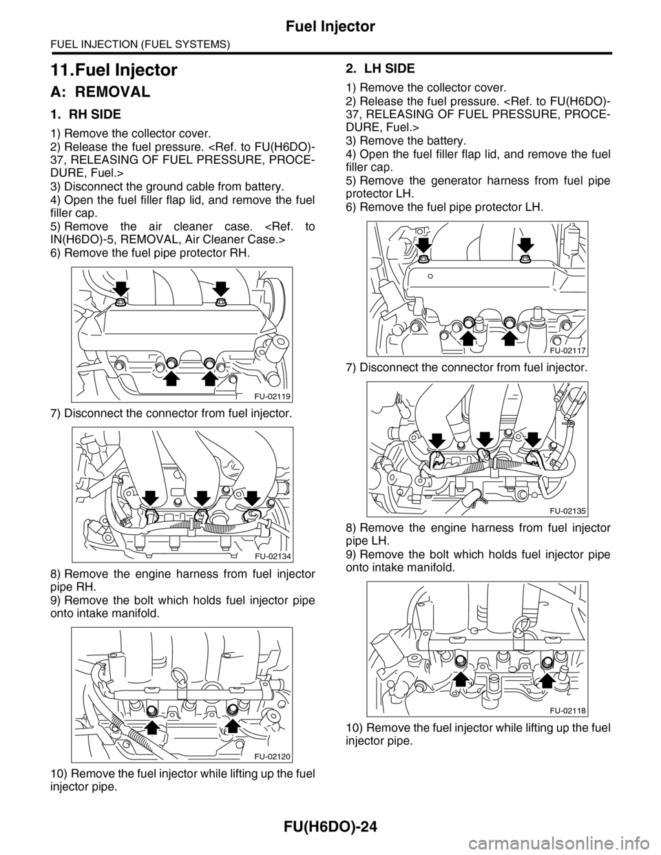
1. RH SIDE
1) Remove the collector cover.
2) Release the fuel pressure.
37, RELEASING OF FUEL PRESSURE, PROCE-
DURE, Fuel.>
3) Disconnect the ground cable from battery.
4) Open the fuel filler flap lid, and remove the fuel
filler cap.
5) Remove the air cleaner case.
IN(H6DO)-5, REMOVAL, Air Cleaner Case.>
6) Remove the fuel pipe protector RH.
7) Disconnect the connector from fuel injector.
8) Remove the engine harness from fuel injector
pipe RH.
9) Remove the bolt which holds fuel injector pipe
onto intake manifold.
10) Remove the fuel injector while lifting up the fuel
injector pipe.
2. LH SIDE
1) Remove the collector cover.
2) Release the fuel pressure.
37, RELEASING OF FUEL PRESSURE, PROCE-
DURE, Fuel.>
3) Remove the battery.
4) Open the fuel filler flap lid, and remove the fuel
filler cap.
5) Remove the generator harness from fuel pipe
protector LH.
6) Remove the fuel pipe protector LH.
7) Disconnect the connector from fuel injector.
8) Remove the engine harness from fuel injector
pipe LH.
9) Remove the bolt which holds fuel injector pipe
onto intake manifold.
10) Remove the fuel injector while lifting up the fuel
injector pipe.
FU-02119
FU-02134
FU-02120
FU-02117
FU-02135
FU-02118
Page 1615 of 2453
GD(H6DO)-3
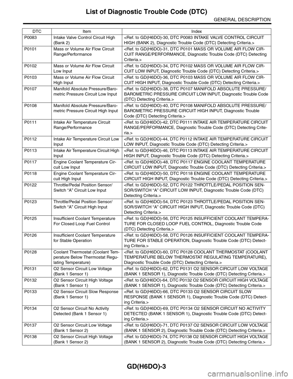
List of Diagnostic Trouble Code (DTC)
GENERAL DESCRIPTION
P0083 Intake Valve Control Circuit High
(Bank 2)
HIGH (BANK 2), Diagnostic Trouble Code (DTC) Detecting Criteria.>
P0101 Mass or Volume Air Flow Circuit
Range/Performance
CUIT RANGE/PERFORMANCE, Diagnostic Trouble Code (DTC) Detecting
Criteria.>
P0102 Mass or Volume Air Flow Circuit
Low Input
CUIT LOW INPUT, Diagnostic Trouble Code (DTC) Detecting Criteria.>
P0103 Mass or Volume Air Flow Circuit
High Input
CUIT HIGH INPUT, Diagnostic Trouble Code (DTC) Detecting Criteria.>
P0107 Manifold Absolute Pressure/Baro-
metric Pressure Circuit Low Input
BAROMETRIC PRESSURE CIRCUIT LOW INPUT, Diagnostic Trouble Code
(DTC) Detecting Criteria.>
P0108 Manifold Absolute Pressure/Baro-
metric Pressure Circuit High Input
BAROMETRIC PRESSURE CIRCUIT HIGH INPUT, Diagnostic Trouble
Code (DTC) Detecting Criteria.>
P0111 Intake Air Temperature Circuit
Range/Performance
RANGE/PERFORMANCE, Diagnostic Trouble Code (DTC) Detecting Crite-
ria.>
P0112 Intake Air Temperature Circuit Low
Input
LOW INPUT, Diagnostic Trouble Code (DTC) Detecting Criteria.>
P0113 Intake Air Temperature Circuit High
Input
HIGH INPUT, Diagnostic Trouble Code (DTC) Detecting Criteria.>
P0117 Engine Coolant Temperature Cir-
cuit Low Input
CIRCUIT LOW INPUT, Diagnostic Trouble Code (DTC) Detecting Criteria.>
P0118 Engine Coolant Temperature Cir-
cuit High Input
CIRCUIT HIGH INPUT, Diagnostic Trouble Code (DTC) Detecting Criteria.>
P0122 Throttle/Pedal Position Sensor/
Switch “A” Circuit Low Input
SOR/SWITCH “A” CIRCUIT LOW INPUT, Diagnostic Trouble Code (DTC)
Detecting Criteria.>
P0123 Throttle/Pedal Position Sensor/
Switch “A” Circuit High Input
SOR/SWITCH “A” CIRCUIT HIGH INPUT, Diagnostic Trouble Code (DTC)
Detecting Criteria.>
P0125 Insufficient Coolant Temperature
For Closed Loop Fuel Control
TURE FOR CLOSED LOOP FUEL CONTROL, Diagnostic Trouble Code
(DTC) Detecting Criteria.>
P0126 Insufficient Coolant Temperature
for Stable Operation
TURE FOR STABLE OPERATION, Diagnostic Trouble Code (DTC) Detect-
ing Criteria.>
P0128 Coolant Thermostat (Coolant Tem-
perature Below Thermostat Regu-
lating Temperature)
TEMPERATURE BELOW THERMOSTAT REGULATING TEMPERATURE),
Diagnostic Trouble Code (DTC) Detecting Criteria.>
P0131 O2 Sensor Circuit Low Voltage
(Bank 1 Sensor 1)
(BANK 1 SENSOR 1), Diagnostic Trouble Code (DTC) Detecting Criteria.>
P0132 O2 Sensor Circuit High Voltage
(Bank 1 Sensor 1)
(BANK 1 SENSOR 1), Diagnostic Trouble Code (DTC) Detecting Criteria.>
P0133 O2 Sensor Circuit Slow Response
(Bank 1 Sensor 1)
RESPONSE (BANK 1 SENSOR 1), Diagnostic Trouble Code (DTC) Detect-
ing Criteria.>
P0134 O2 Sensor Circuit No Activity
Detected (Bank 1 Sensor 1)
DETECTED (BANK 1 SENSOR 1), Diagnostic Trouble Code (DTC) Detect-
ing Criteria.>
P0137 O2 Sensor Circuit Low Voltage
(Bank 1 Sensor 2)
(BANK 1 SENSOR 2), Diagnostic Trouble Code (DTC) Detecting Criteria.>
P0138 O2 Sensor Circuit High Voltage
(Bank 1 Sensor 2)
(BANK 1 SENSOR 2), Diagnostic Trouble Code (DTC) Detecting Criteria.>
DTC Item Index
Page 1638 of 2453
GD(H6DO)-26
Diagnostic Trouble Code (DTC) Detecting Criteria
GENERAL DESCRIPTION
Q: DTC P0068 MAP/MAF - THROTTLE POSITION CORRELATION
1. OUTLINE OF DIAGNOSIS
Detect problems in the intake manifold pressure sensor output properties. Determining from the engine con-
dition, if the intake manifold pressure AD value is small even when operating conditions suggest it should be
large, or if the intake manifold pressure AD value is large even though the operating condition suggest it
should be small, this is judged as being NG.
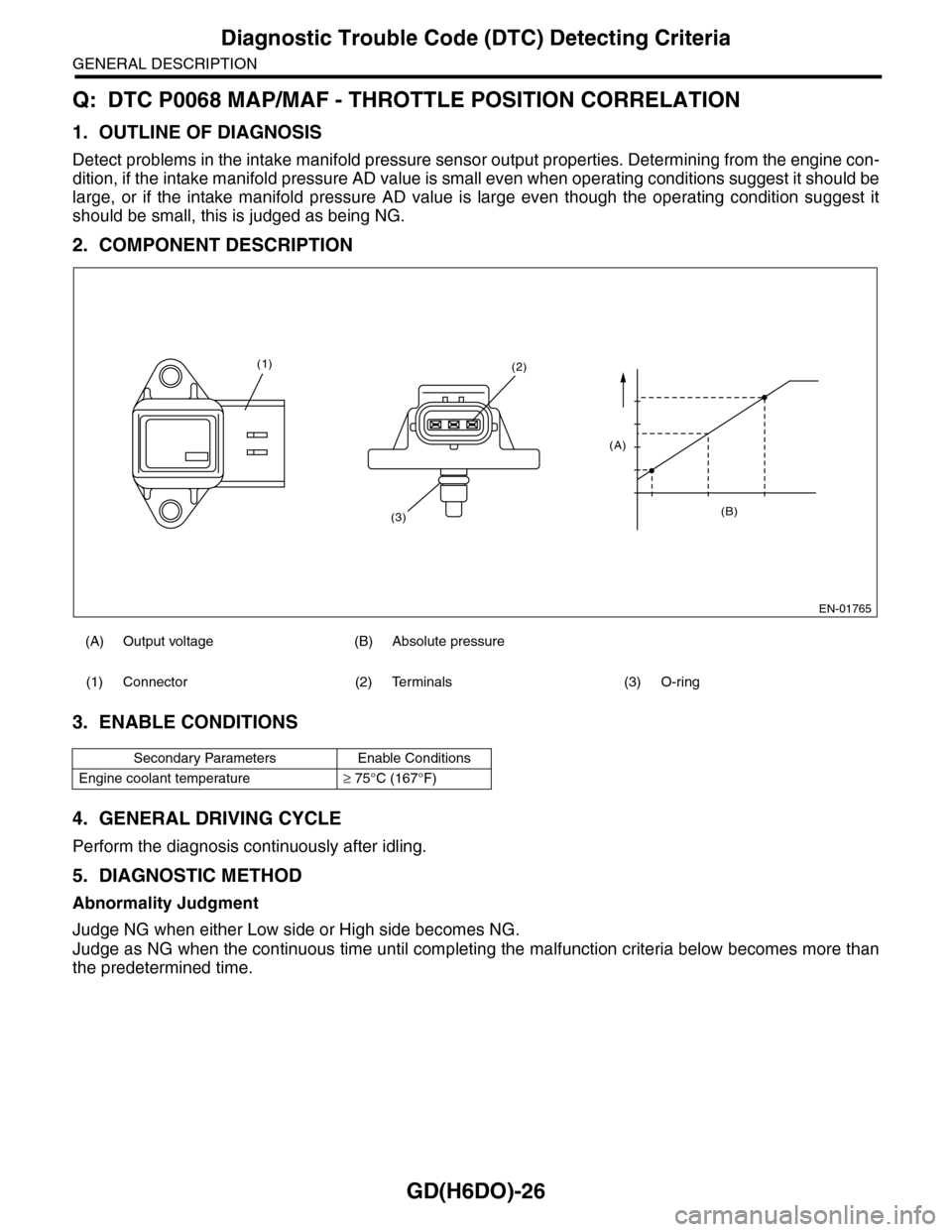
2. COMPONENT DESCRIPTION
3. ENABLE CONDITIONS
4. GENERAL DRIVING CYCLE
Perform the diagnosis continuously after idling.
5. DIAGNOSTIC METHOD
Abnormality Judgment
Judge NG when either Low side or High side becomes NG.
Judge as NG when the continuous time until completing the malfunction criteria below becomes more than
the predetermined time.
(A) Output voltage (B) Absolute pressure
(1) Connector (2) Terminals (3) O-ring
Secondary Parameters Enable Conditions
Engine coolant temperature≥ 75°C (167°F)
EN-01765
(B)
(A)
(2)
(3)
(1)
Page 1639 of 2453
GD(H6DO)-27
Diagnostic Trouble Code (DTC) Detecting Criteria
GENERAL DESCRIPTION
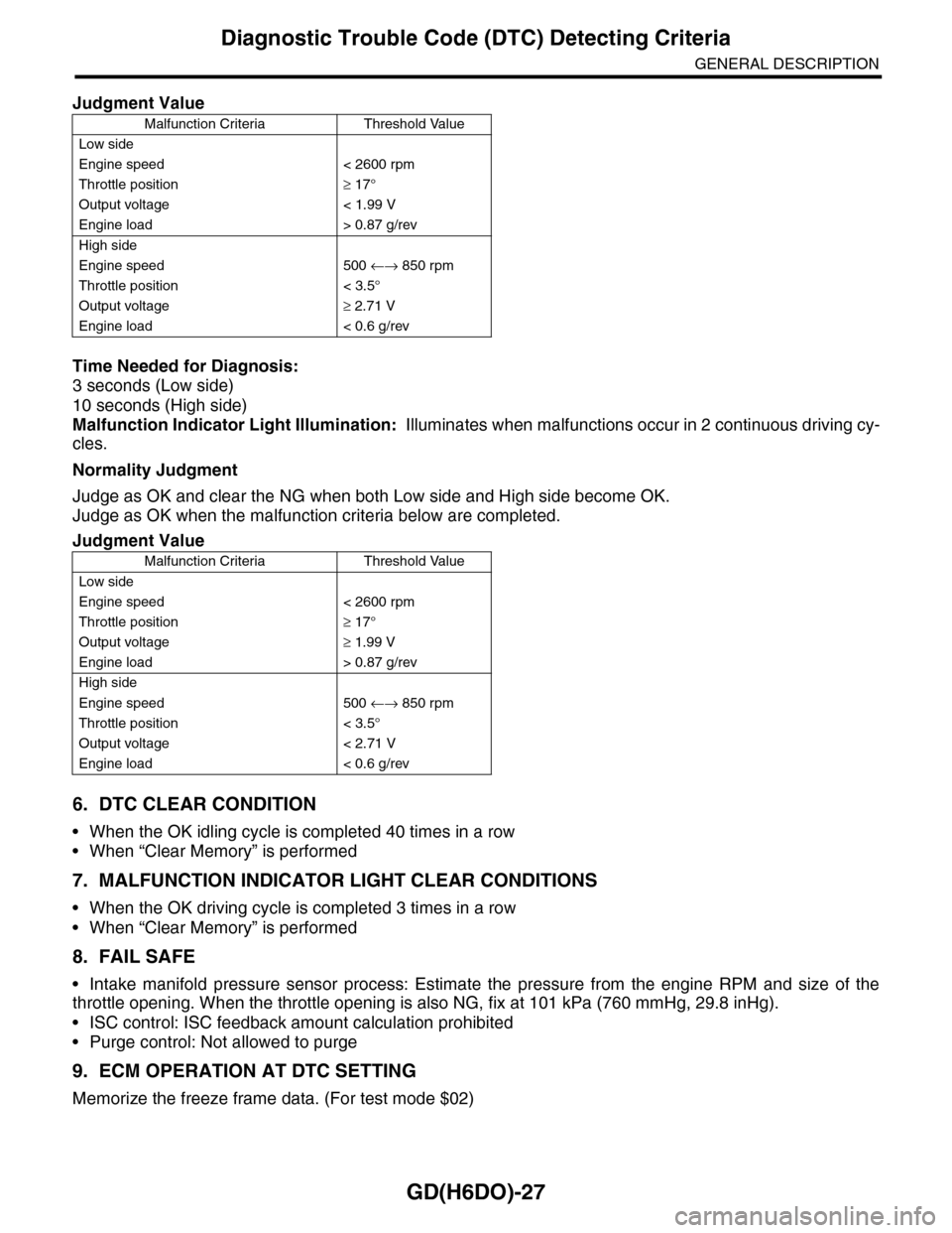
Time Needed for Diagnosis:
3 seconds (Low side)
10 seconds (High side)
Malfunction Indicator Light Illumination: Illuminates when malfunctions occur in 2 continuous driving cy-
cles.
Normality Judgment
Judge as OK and clear the NG when both Low side and High side become OK.
Judge as OK when the malfunction criteria below are completed.
6. DTC CLEAR CONDITION
•When the OK idling cycle is completed 40 times in a row
•When “Clear Memory” is performed
7. MALFUNCTION INDICATOR LIGHT CLEAR CONDITIONS
•When the OK driving cycle is completed 3 times in a row
•When “Clear Memory” is performed
8. FAIL SAFE
•Intake manifold pressure sensor process: Estimate the pressure from the engine RPM and size of the
throttle opening. When the throttle opening is also NG, fix at 101 kPa (760 mmHg, 29.8 inHg).
•ISC control: ISC feedback amount calculation prohibited
•Purge control: Not allowed to purge
9. ECM OPERATION AT DTC SETTING
Memorize the freeze frame data. (For test mode $02)
Judgment Value
Malfunction Criteria Threshold Value
Low side
Engine speed < 2600 rpm
Throttle position≥ 17°
Output voltage < 1.99 V
Engine load > 0.87 g/rev
High side
Engine speed 500 ←→ 850 rpm
Throttle position < 3.5°
Output voltage≥ 2.71 V
Engine load < 0.6 g/rev
Judgment Value
Malfunction Criteria Threshold Value
Low side
Engine speed < 2600 rpm
Throttle position≥ 17°
Output voltage≥ 1.99 V
Engine load > 0.87 g/rev
High side
Engine speed 500 ←→ 850 rpm
Throttle position < 3.5°
Output voltage < 2.71 V
Engine load < 0.6 g/rev
Page 1644 of 2453
GD(H6DO)-32
Diagnostic Trouble Code (DTC) Detecting Criteria
GENERAL DESCRIPTION
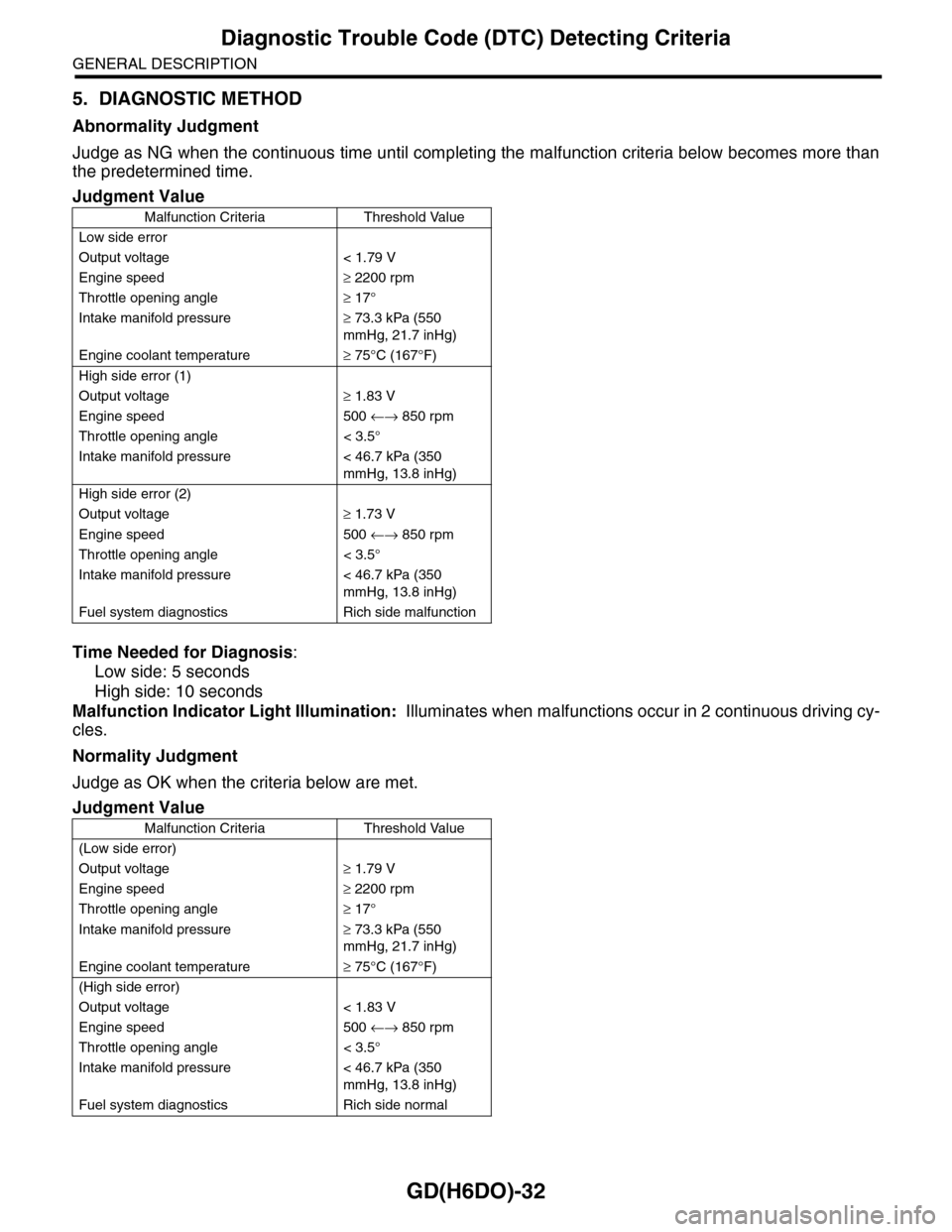
5. DIAGNOSTIC METHOD
Abnormality Judgment
Judge as NG when the continuous time until completing the malfunction criteria below becomes more than
the predetermined time.
Time Needed for Diagnosis:
Low side: 5 seconds
High side: 10 seconds
Malfunction Indicator Light Illumination: Illuminates when malfunctions occur in 2 continuous driving cy-
cles.
Normality Judgment
Judge as OK when the criteria below are met.
Judgment Value
Malfunction Criteria Threshold Value
Low side error
Output voltage < 1.79 V
Engine speed≥ 2200 rpm
Throttle opening angle≥ 17°
Intake manifold pressure≥ 73.3 kPa (550
mmHg, 21.7 inHg)
Engine coolant temperature≥ 75°C (167°F)
High side error (1)
Output voltage≥ 1.83 V
Engine speed 500 ←→ 850 rpm
Throttle opening angle < 3.5°
Intake manifold pressure < 46.7 kPa (350
mmHg, 13.8 inHg)
High side error (2)
Output voltage≥ 1.73 V
Engine speed 500 ←→ 850 rpm
Throttle opening angle < 3.5°
Intake manifold pressure < 46.7 kPa (350
mmHg, 13.8 inHg)
Fuel system diagnostics Rich side malfunction
Judgment Value
Malfunction Criteria Threshold Value
(Low side error)
Output voltage≥ 1.79 V
Engine speed≥ 2200 rpm
Throttle opening angle≥ 17°
Intake manifold pressure≥ 73.3 kPa (550
mmHg, 21.7 inHg)
Engine coolant temperature≥ 75°C (167°F)
(High side error)
Output voltage < 1.83 V
Engine speed 500 ←→ 850 rpm
Throttle opening angle < 3.5°
Intake manifold pressure < 46.7 kPa (350
mmHg, 13.8 inHg)
Fuel system diagnostics Rich side normal
Page 1650 of 2453
GD(H6DO)-38
Diagnostic Trouble Code (DTC) Detecting Criteria
GENERAL DESCRIPTION
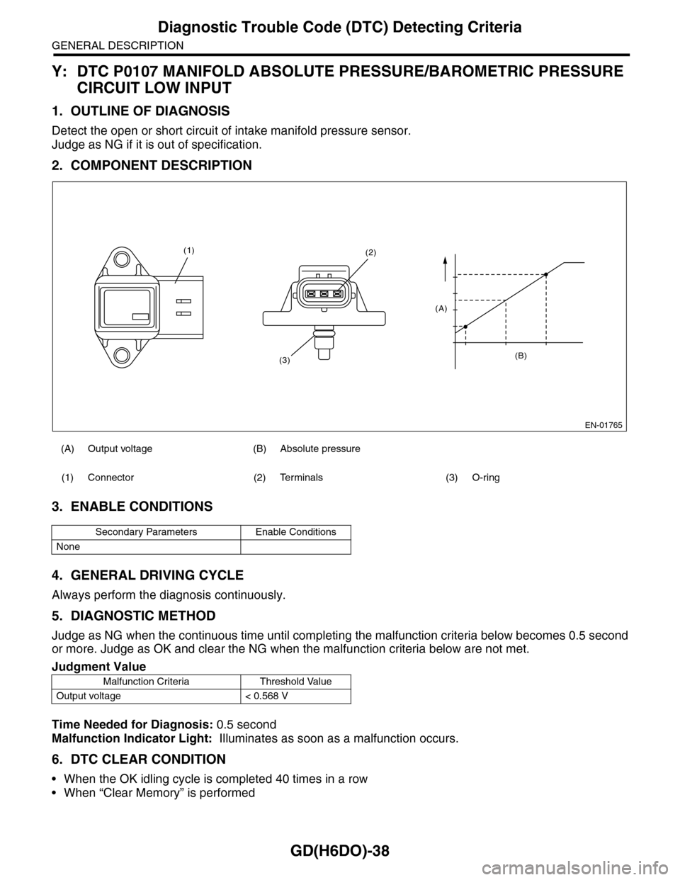
Y: DTC P0107 MANIFOLD ABSOLUTE PRESSURE/BAROMETRIC PRESSURE
CIRCUIT LOW INPUT
1. OUTLINE OF DIAGNOSIS
Detect the open or short circuit of intake manifold pressure sensor.
Judge as NG if it is out of specification.
2. COMPONENT DESCRIPTION
3. ENABLE CONDITIONS
4. GENERAL DRIVING CYCLE
Always perform the diagnosis continuously.
5. DIAGNOSTIC METHOD
Judge as NG when the continuous time until completing the malfunction criteria below becomes 0.5 second
or more. Judge as OK and clear the NG when the malfunction criteria below are not met.
Time Needed for Diagnosis: 0.5 second
Malfunction Indicator Light: Illuminates as soon as a malfunction occurs.
6. DTC CLEAR CONDITION
•When the OK idling cycle is completed 40 times in a row
•When “Clear Memory” is performed
(A) Output voltage (B) Absolute pressure
(1) Connector (2) Terminals (3) O-ring
Secondary Parameters Enable Conditions
None
Judgment Value
Malfunction Criteria Threshold Value
Output voltage < 0.568 V
EN-01765
(B)
(A)
(2)
(3)
(1)