2009 SUBARU TRIBECA turn signal
[x] Cancel search: turn signalPage 1669 of 2453
GD(H6DO)-57
Diagnostic Trouble Code (DTC) Detecting Criteria
GENERAL DESCRIPTION
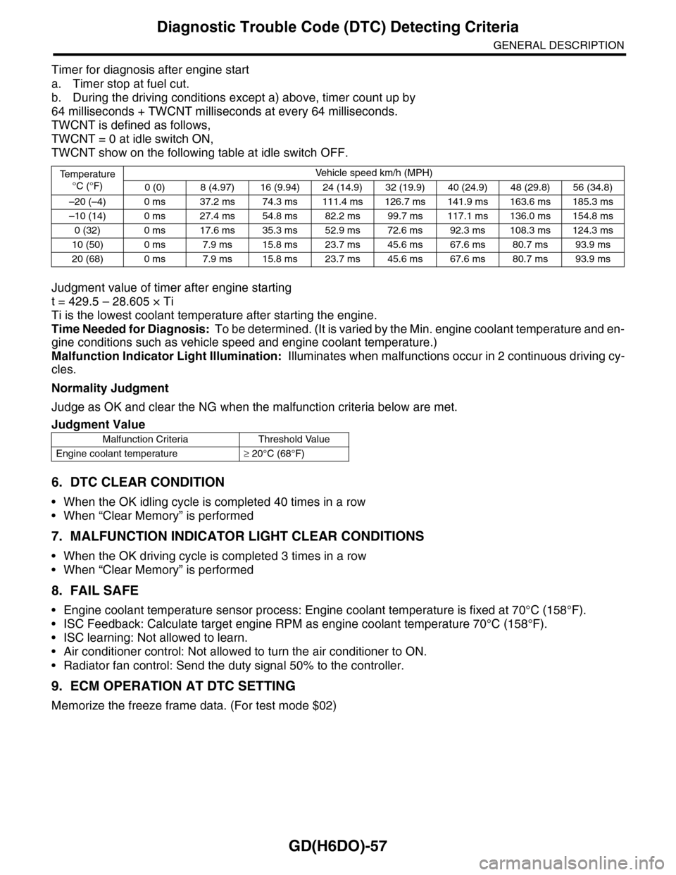
Timer for diagnosis after engine start
a. Timer stop at fuel cut.
b. During the driving conditions except a) above, timer count up by
64 milliseconds + TWCNT milliseconds at every 64 milliseconds.
TWCNT is defined as follows,
TWCNT = 0 at idle switch ON,
TWCNT show on the following table at idle switch OFF.
Judgment value of timer after engine starting
t = 429.5 – 28.605 × Ti
Ti is the lowest coolant temperature after starting the engine.
Time Needed for Diagnosis: To be determined. (It is varied by the Min. engine coolant temperature and en-
gine conditions such as vehicle speed and engine coolant temperature.)
Malfunction Indicator Light Illumination: Illuminates when malfunctions occur in 2 continuous driving cy-
cles.
Normality Judgment
Judge as OK and clear the NG when the malfunction criteria below are met.
6. DTC CLEAR CONDITION
•When the OK idling cycle is completed 40 times in a row
•When “Clear Memory” is performed
7. MALFUNCTION INDICATOR LIGHT CLEAR CONDITIONS
•When the OK driving cycle is completed 3 times in a row
•When “Clear Memory” is performed
8. FAIL SAFE
•Engine coolant temperature sensor process: Engine coolant temperature is fixed at 70°C (158°F).
•ISC Feedback: Calculate target engine RPM as engine coolant temperature 70°C (158°F).
•ISC learning: Not allowed to learn.
•Air conditioner control: Not allowed to turn the air conditioner to ON.
•Radiator fan control: Send the duty signal 50% to the controller.
9. ECM OPERATION AT DTC SETTING
Memorize the freeze frame data. (For test mode $02)
Te m p e r a t u r e
°C (°F)
Ve h i c l e s p e e d k m / h ( M P H )
0 (0) 8 (4.97) 16 (9.94) 24 (14.9) 32 (19.9) 40 (24.9) 48 (29.8) 56 (34.8)
–20 (–4) 0 ms 37.2 ms 74.3 ms 111.4 ms 126.7 ms 141.9 ms 163.6 ms 185.3 ms
–10 (14) 0 ms 27.4 ms 54.8 ms 82.2 ms 99.7 ms 117.1 ms 136.0 ms 154.8 ms
0 (32) 0 ms 17.6 ms 35.3 ms 52.9 ms 72.6 ms 92.3 ms 108.3 ms 124.3 ms
10 (50) 0 ms 7.9 ms 15.8 ms 23.7 ms 45.6 ms 67.6 ms 80.7 ms 93.9 ms
20 (68) 0 ms 7.9 ms 15.8 ms 23.7 ms 45.6 ms 67.6 ms 80.7 ms 93.9 ms
Judgment Value
Malfunction Criteria Threshold Value
Engine coolant temperature≥ 20°C (68°F)
Page 1726 of 2453
GD(H6DO)-114
Diagnostic Trouble Code (DTC) Detecting Criteria
GENERAL DESCRIPTION
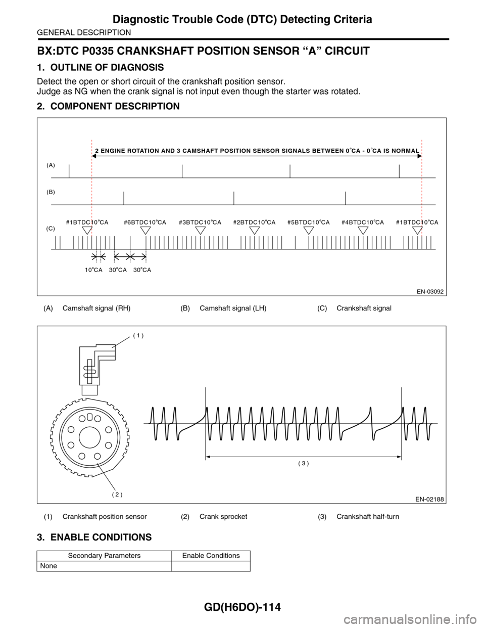
BX:DTC P0335 CRANKSHAFT POSITION SENSOR “A” CIRCUIT
1. OUTLINE OF DIAGNOSIS
Detect the open or short circuit of the crankshaft position sensor.
Judge as NG when the crank signal is not input even though the starter was rotated.
2. COMPONENT DESCRIPTION
3. ENABLE CONDITIONS
(A) Camshaft signal (RH) (B) Camshaft signal (LH) (C) Crankshaft signal
(1) Crankshaft position sensor (2) Crank sprocket (3) Crankshaft half-turn
Secondary Parameters Enable Conditions
None
(A)
(C)#6BTDC10 CA#3BTDC10 CA#2BTDC10 CA#5BTDC10 CA#4BTDC10 CA
10 CA30 CA30 CA
#1BTDC10 CA#1BTDC10 CA
EN-03092
(B)
2 ENGINE ROTATION AND 3 CAMSHAFT POSITION SENSOR SIGNALS BETWEEN 0 CA - 0 CA IS NORMAL
EN-02188
( 1 )
( 2 )
( 3 )
Page 1728 of 2453
GD(H6DO)-116
Diagnostic Trouble Code (DTC) Detecting Criteria
GENERAL DESCRIPTION
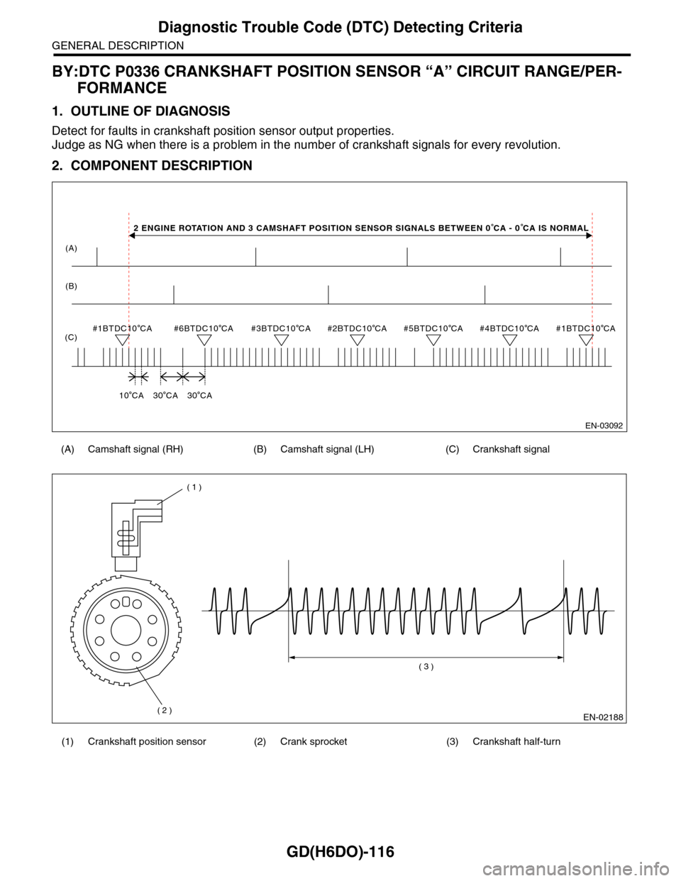
BY:DTC P0336 CRANKSHAFT POSITION SENSOR “A” CIRCUIT RANGE/PER-
FORMANCE
1. OUTLINE OF DIAGNOSIS
Detect for faults in crankshaft position sensor output properties.
Judge as NG when there is a problem in the number of crankshaft signals for every revolution.
2. COMPONENT DESCRIPTION
(A) Camshaft signal (RH) (B) Camshaft signal (LH) (C) Crankshaft signal
(1) Crankshaft position sensor (2) Crank sprocket (3) Crankshaft half-turn
(A)
(C)#6BTDC10 CA#3BTDC10 CA#2BTDC10 CA#5BTDC10 CA#4BTDC10 CA
10 CA30 CA30 CA
#1BTDC10 CA#1BTDC10 CA
EN-03092
(B)
2 ENGINE ROTATION AND 3 CAMSHAFT POSITION SENSOR SIGNALS BETWEEN 0 CA - 0 CA IS NORMAL
EN-02188
( 1 )
( 2 )
( 3 )
Page 1803 of 2453
GD(H6DO)-191
Diagnostic Trouble Code (DTC) Detecting Criteria
GENERAL DESCRIPTION
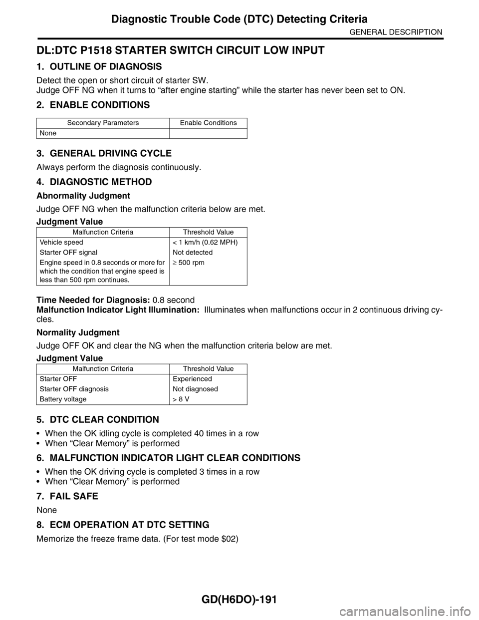
DL:DTC P1518 STARTER SWITCH CIRCUIT LOW INPUT
1. OUTLINE OF DIAGNOSIS
Detect the open or short circuit of starter SW.
Judge OFF NG when it turns to “after engine starting” while the starter has never been set to ON.
2. ENABLE CONDITIONS
3. GENERAL DRIVING CYCLE
Always perform the diagnosis continuously.
4. DIAGNOSTIC METHOD
Abnormality Judgment
Judge OFF NG when the malfunction criteria below are met.
Time Needed for Diagnosis: 0.8 second
Malfunction Indicator Light Illumination: Illuminates when malfunctions occur in 2 continuous driving cy-
cles.
Normality Judgment
Judge OFF OK and clear the NG when the malfunction criteria below are met.
5. DTC CLEAR CONDITION
•When the OK idling cycle is completed 40 times in a row
•When “Clear Memory” is performed
6. MALFUNCTION INDICATOR LIGHT CLEAR CONDITIONS
•When the OK driving cycle is completed 3 times in a row
•When “Clear Memory” is performed
7. FAIL SAFE
None
8. ECM OPERATION AT DTC SETTING
Memorize the freeze frame data. (For test mode $02)
Secondary Parameters Enable Conditions
None
Judgment Value
Malfunction Criteria Threshold Value
Ve h i c l e s p e e d < 1 k m / h ( 0 . 6 2 M P H )
Starter OFF signal Not detected
Engine speed in 0.8 seconds or more for
which the condition that engine speed is
less than 500 rpm continues.
≥ 500 rpm
Judgment Value
Malfunction Criteria Threshold Value
Starter OFF Experienced
Starter OFF diagnosis Not diagnosed
Battery voltage > 8 V
Page 2139 of 2453
5AT(diag)-22
SPORT Indicator Light Display
AUTOMATIC TRANSMISSION (DIAGNOSTICS)
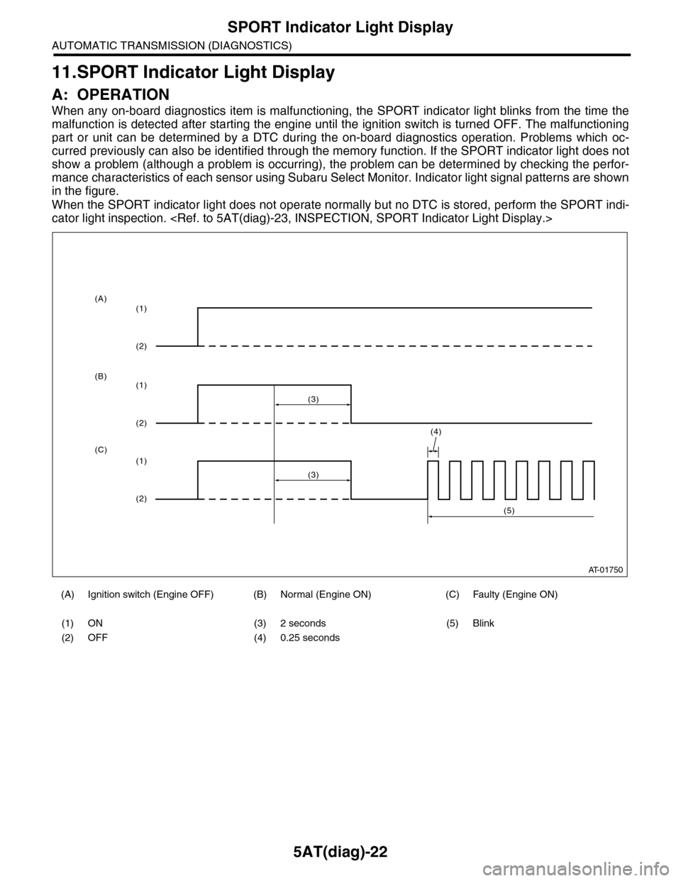
11.SPORT Indicator Light Display
A: OPERATION
When any on-board diagnostics item is malfunctioning, the SPORT indicator light blinks from the time the
malfunction is detected after starting the engine until the ignition switch is turned OFF. The malfunctioning
part or unit can be determined by a DTC during the on-board diagnostics operation. Problems which oc-
curred previously can also be identified through the memory function. If the SPORT indicator light does not
show a problem (although a problem is occurring), the problem can be determined by checking the perfor-
mance characteristics of each sensor using Subaru Select Monitor. Indicator light signal patterns are shown
in the figure.
When the SPORT indicator light does not operate normally but no DTC is stored, perform the SPORT indi-
cator light inspection.
(A) Ignition switch (Engine OFF) (B) Normal (Engine ON) (C) Faulty (Engine ON)
(1) ON (3) 2 seconds (5) Blink
(2) OFF (4) 0.25 seconds
AT-01750
(4)
(3)
(1)
(2)
(1)
(2)
(1)
(2)
(3)
(5)
(A)
(B)
(C)
Page 2143 of 2453
5AT(diag)-26
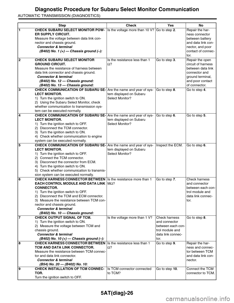
Diagnostic Procedure for Subaru Select Monitor Communication
AUTOMATIC TRANSMISSION (DIAGNOSTICS)
Step Check Yes No
1CHECK SUBARU SELECT MONITOR POW-
ER SUPPLY CIRCUIT.
Measure the voltage between data link con-
nector and chassis ground.
Connector & terminal
(B402) No. 1 (+) — Chassis ground (–):
Is the voltage more than 10 V? Go to step 2.Repair the har-
ness connector
between battery
and data link con-
nector, and poor
contact of connec-
tor.
2CHECK SUBARU SELECT MONITOR
GROUND CIRCUIT.
Measure the resistance of harness between
data link connector and chassis ground.
Connector & terminal
(B402) No. 12 — Chassis ground:
(B402) No. 13 — Chassis ground:
Is the resistance less than 1
Ω?
Go to step 3.Repair the open
circuit of harness
between data link
connector and
ground terminal,
and poor contact
of connector.
3CHECK COMMUNICATION OF SUBARU SE-
LECT MONITOR.
1) Turn the ignition switch to ON.
2) Using the Subaru Select Monitor, check
whether communication to transmission sys-
tem can be executed normally.
Are the name and year of sys-
tem displayed on Subaru
Select Monitor?
Go to step 8.Go to step 4.
4CHECK COMMUNICATION OF SUBARU SE-
LECT MONITOR.
1) Turn the ignition switch to OFF.
2) Disconnect the TCM connector.
3) Turn the ignition switch to ON.
4) Check whether communication to engine
system can be executed normally.
Are the name and year of sys-
tem displayed on Subaru
Select Monitor?
Go to step 6.Go to step 5.
5CHECK COMMUNICATION OF SUBARU SE-
LECT MONITOR.
1) Turn the ignition switch to OFF.
2) Connect the TCM connector.
3) Disconnect the connector from ECM.
4) Turn the ignition switch to ON.
5) Check whether communication to transmis-
sion system can be executed normally.
Are the name and year of sys-
tem displayed on Subaru
Select Monitor?
Inspect the ECM. Go to step 6.
6CHECK HARNESS CONNECTOR BETWEEN
EACH CONTROL MODULE AND DATA LINK
CONNECTOR.
1) Turn the ignition switch to OFF.
2) Disconnect the TCM and ECM connector.
3) Measure the resistance between TCM con-
nector and chassis ground.
Connector & terminal
(B402) No. 10 — Chassis ground:
Is the resistance more than 1
MΩ?
Go to step 7.Check harness
and connector
between each con-
trol module and
data link connec-
tor.
7CHECK OUTPUT SIGNAL OF TCM.
1) Turn the ignition switch to ON.
2) Measure the voltage between TCM and
chassis ground.
Connector & terminal
(B402) No. 10 (+) — Chassis ground (–):
Is the voltage more than 1 V? Check harness
and connector
between each con-
trol module and
data link connec-
tor.
Go to step 8.
8CHECK HARNESS CONNECTOR BETWEEN
TCM AND DATA LINK CONNECTOR.
Measure the resistance between TCM connec-
tor and data link connector.
Connector & terminal
(B54) No. 20 — (B402) No. 10:
Is the resistance less than 1
Ω?
Go to step 9.Repair the har-
ness and connec-
tor between TCM
and data link con-
nector.
9CHECK INSTALLATION OF TCM CONNEC-
TOR.
Tu r n t h e i g n i t i o n s w i t c h t o O F F.
Is TCM connector connected
to TCM?
Go to step 10.Connect the TCM
connector to TCM.
Page 2150 of 2453
5AT(diag)-33
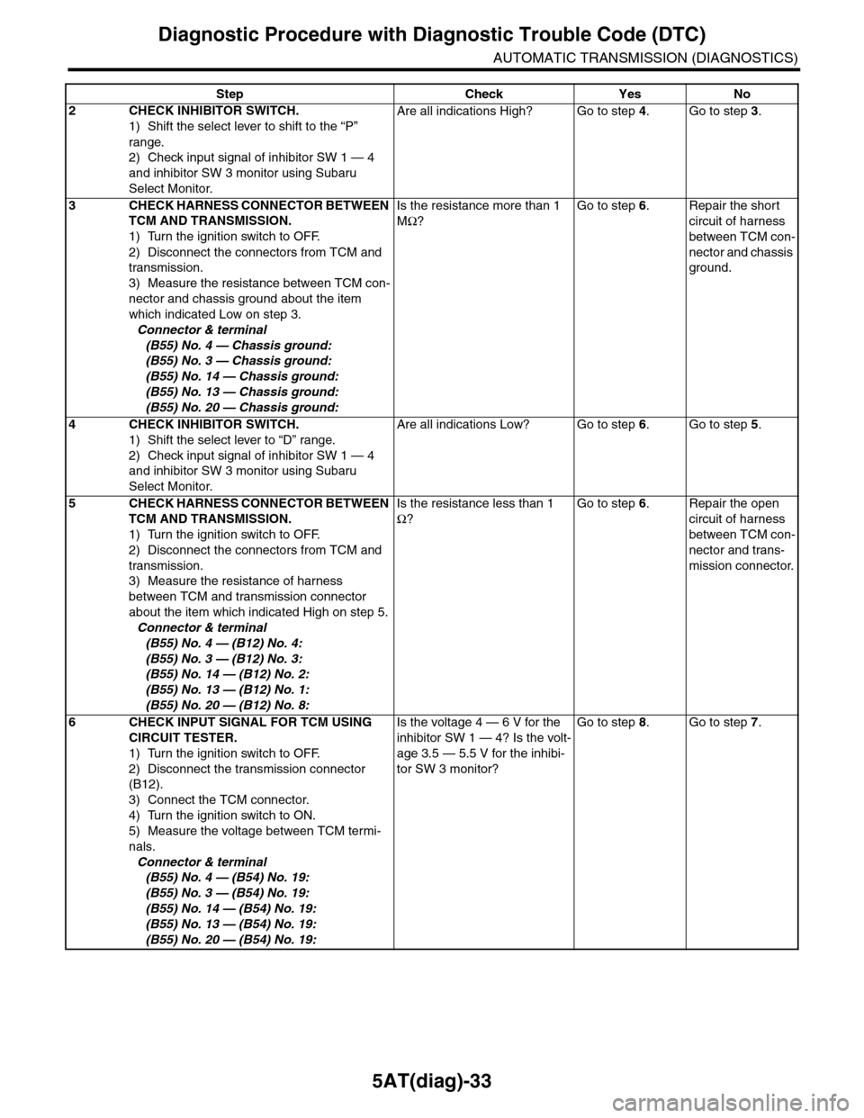
Diagnostic Procedure with Diagnostic Trouble Code (DTC)
AUTOMATIC TRANSMISSION (DIAGNOSTICS)
2CHECK INHIBITOR SWITCH.
1) Shift the select lever to shift to the “P”
range.
2) Check input signal of inhibitor SW 1 — 4
and inhibitor SW 3 monitor using Subaru
Select Monitor.
Are all indications High? Go to step 4.Go to step 3.
3CHECK HARNESS CONNECTOR BETWEEN
TCM AND TRANSMISSION.
1) Turn the ignition switch to OFF.
2) Disconnect the connectors from TCM and
transmission.
3) Measure the resistance between TCM con-
nector and chassis ground about the item
which indicated Low on step 3.
Connector & terminal
(B55) No. 4 — Chassis ground:
(B55) No. 3 — Chassis ground:
(B55) No. 14 — Chassis ground:
(B55) No. 13 — Chassis ground:
(B55) No. 20 — Chassis ground:
Is the resistance more than 1
MΩ?
Go to step 6.Repair the short
circuit of harness
between TCM con-
nector and chassis
ground.
4CHECK INHIBITOR SWITCH.
1) Shift the select lever to “D” range.
2) Check input signal of inhibitor SW 1 — 4
and inhibitor SW 3 monitor using Subaru
Select Monitor.
Are all indications Low? Go to step 6.Go to step 5.
5CHECK HARNESS CONNECTOR BETWEEN
TCM AND TRANSMISSION.
1) Turn the ignition switch to OFF.
2) Disconnect the connectors from TCM and
transmission.
3) Measure the resistance of harness
between TCM and transmission connector
about the item which indicated High on step 5.
Connector & terminal
(B55) No. 4 — (B12) No. 4:
(B55) No. 3 — (B12) No. 3:
(B55) No. 14 — (B12) No. 2:
(B55) No. 13 — (B12) No. 1:
(B55) No. 20 — (B12) No. 8:
Is the resistance less than 1
Ω?
Go to step 6.Repair the open
circuit of harness
between TCM con-
nector and trans-
mission connector.
6CHECK INPUT SIGNAL FOR TCM USING
CIRCUIT TESTER.
1) Turn the ignition switch to OFF.
2) Disconnect the transmission connector
(B12).
3) Connect the TCM connector.
4) Turn the ignition switch to ON.
5) Measure the voltage between TCM termi-
nals.
Connector & terminal
(B55) No. 4 — (B54) No. 19:
(B55) No. 3 — (B54) No. 19:
(B55) No. 14 — (B54) No. 19:
(B55) No. 13 — (B54) No. 19:
(B55) No. 20 — (B54) No. 19:
Is the voltage 4 — 6 V for the
inhibitor SW 1 — 4? Is the volt-
age 3.5 — 5.5 V for the inhibi-
tor SW 3 monitor?
Go to step 8.Go to step 7.
Step Check Yes No
Page 2151 of 2453
5AT(diag)-34
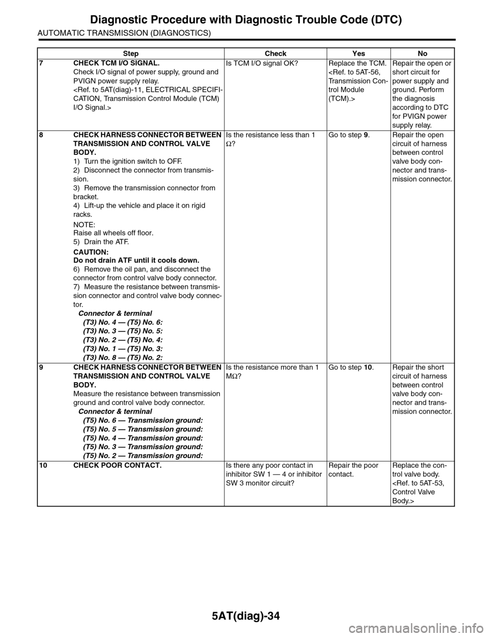
Diagnostic Procedure with Diagnostic Trouble Code (DTC)
AUTOMATIC TRANSMISSION (DIAGNOSTICS)
7CHECK TCM I/O SIGNAL.
Check I/O signal of power supply, ground and
PVIGN power supply relay.
I/O Signal.>
Is TCM I/O signal OK? Replace the TCM.
trol Module
(TCM).>
Repair the open or
short circuit for
power supply and
ground. Perform
the diagnosis
according to DTC
for PVIGN power
supply relay.
8CHECK HARNESS CONNECTOR BETWEEN
TRANSMISSION AND CONTROL VALVE
BODY.
1) Turn the ignition switch to OFF.
2) Disconnect the connector from transmis-
sion.
3) Remove the transmission connector from
bracket.
4) Lift-up the vehicle and place it on rigid
racks.
NOTE:
Raise all wheels off floor.
5) Drain the ATF.
CAUTION:Do not drain ATF until it cools down.
6) Remove the oil pan, and disconnect the
connector from control valve body connector.
7) Measure the resistance between transmis-
sion connector and control valve body connec-
tor.
Connector & terminal
(T3) No. 4 — (T5) No. 6:
(T3) No. 3 — (T5) No. 5:
(T3) No. 2 — (T5) No. 4:
(T3) No. 1 — (T5) No. 3:
(T3) No. 8 — (T5) No. 2:
Is the resistance less than 1
Ω?
Go to step 9.Repair the open
circuit of harness
between control
valve body con-
nector and trans-
mission connector.
9CHECK HARNESS CONNECTOR BETWEEN
TRANSMISSION AND CONTROL VALVE
BODY.
Measure the resistance between transmission
ground and control valve body connector.
Connector & terminal
(T5) No. 6 — Transmission ground:
(T5) No. 5 — Transmission ground:
(T5) No. 4 — Transmission ground:
(T5) No. 3 — Transmission ground:
(T5) No. 2 — Transmission ground:
Is the resistance more than 1
MΩ?
Go to step 10.Repair the short
circuit of harness
between control
valve body con-
nector and trans-
mission connector.
10 CHECK POOR CONTACT.Is there any poor contact in
inhibitor SW 1 — 4 or inhibitor
SW 3 monitor circuit?
Repair the poor
contact.
Replace the con-
trol valve body.
Body.>
Step Check Yes No