2009 SUBARU TRIBECA turn signal
[x] Cancel search: turn signalPage 1544 of 2453
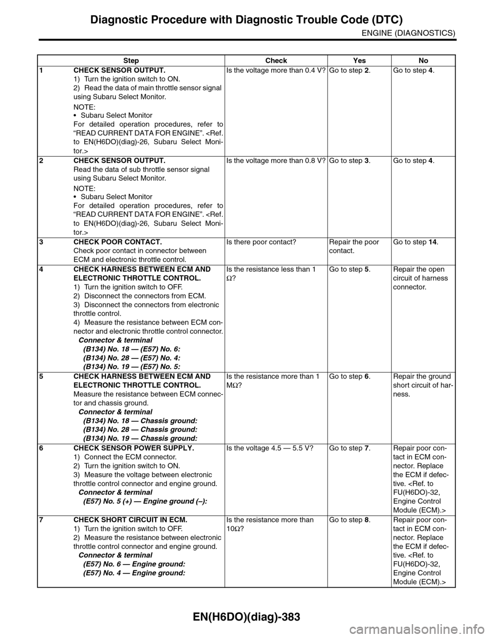
EN(H6DO)(diag)-383
Diagnostic Procedure with Diagnostic Trouble Code (DTC)
ENGINE (DIAGNOSTICS)
Step Check Yes No
1CHECK SENSOR OUTPUT.
1) Turn the ignition switch to ON.
2) Read the data of main throttle sensor signal
using Subaru Select Monitor.
NOTE:•Subaru Select Monitor
For detailed operation procedures, refer to
“READ CURRENT DATA FOR ENGINE”.
tor.>
Is the voltage more than 0.4 V? Go to step 2.Go to step 4.
2CHECK SENSOR OUTPUT.
Read the data of sub throttle sensor signal
using Subaru Select Monitor.
NOTE:•Subaru Select Monitor
For detailed operation procedures, refer to
“READ CURRENT DATA FOR ENGINE”.
tor.>
Is the voltage more than 0.8 V? Go to step 3.Go to step 4.
3CHECK POOR CONTACT.
Check poor contact in connector between
ECM and electronic throttle control.
Is there poor contact? Repair the poor
contact.
Go to step 14.
4CHECK HARNESS BETWEEN ECM AND
ELECTRONIC THROTTLE CONTROL.
1) Turn the ignition switch to OFF.
2) Disconnect the connectors from ECM.
3) Disconnect the connectors from electronic
throttle control.
4) Measure the resistance between ECM con-
nector and electronic throttle control connector.
Connector & terminal
(B134) No. 18 — (E57) No. 6:
(B134) No. 28 — (E57) No. 4:
(B134) No. 19 — (E57) No. 5:
Is the resistance less than 1
Ω?
Go to step 5.Repair the open
circuit of harness
connector.
5CHECK HARNESS BETWEEN ECM AND
ELECTRONIC THROTTLE CONTROL.
Measure the resistance between ECM connec-
tor and chassis ground.
Connector & terminal
(B134) No. 18 — Chassis ground:
(B134) No. 28 — Chassis ground:
(B134) No. 19 — Chassis ground:
Is the resistance more than 1
MΩ?
Go to step 6.Repair the ground
short circuit of har-
ness.
6CHECK SENSOR POWER SUPPLY.
1) Connect the ECM connector.
2) Turn the ignition switch to ON.
3) Measure the voltage between electronic
throttle control connector and engine ground.
Connector & terminal
(E57) No. 5 (+) — Engine ground (–):
Is the voltage 4.5 — 5.5 V? Go to step 7.Repair poor con-
tact in ECM con-
nector. Replace
the ECM if defec-
tive.
Engine Control
Module (ECM).>
7CHECK SHORT CIRCUIT IN ECM.
1) Turn the ignition switch to OFF.
2) Measure the resistance between electronic
throttle control connector and engine ground.
Connector & terminal
(E57) No. 6 — Engine ground:
(E57) No. 4 — Engine ground:
Is the resistance more than
10Ω?
Go to step 8.Repair poor con-
tact in ECM con-
nector. Replace
the ECM if defec-
tive.
Engine Control
Module (ECM).>
Page 1545 of 2453
EN(H6DO)(diag)-384
Diagnostic Procedure with Diagnostic Trouble Code (DTC)
ENGINE (DIAGNOSTICS)
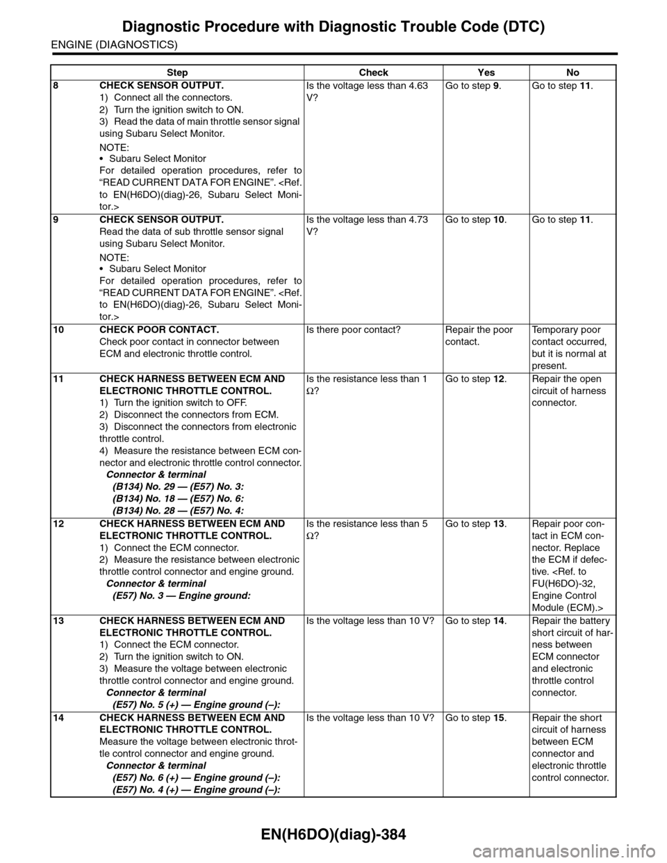
8CHECK SENSOR OUTPUT.
1) Connect all the connectors.
2) Turn the ignition switch to ON.
3) Read the data of main throttle sensor signal
using Subaru Select Monitor.
NOTE:
•Subaru Select Monitor
For detailed operation procedures, refer to
“READ CURRENT DATA FOR ENGINE”.
tor.>
Is the voltage less than 4.63
V?
Go to step 9.Go to step 11.
9CHECK SENSOR OUTPUT.
Read the data of sub throttle sensor signal
using Subaru Select Monitor.
NOTE:•Subaru Select Monitor
For detailed operation procedures, refer to
“READ CURRENT DATA FOR ENGINE”.
tor.>
Is the voltage less than 4.73
V?
Go to step 10.Go to step 11.
10 CHECK POOR CONTACT.
Check poor contact in connector between
ECM and electronic throttle control.
Is there poor contact? Repair the poor
contact.
Te m p o r a r y p o o r
contact occurred,
but it is normal at
present.
11 CHECK HARNESS BETWEEN ECM AND
ELECTRONIC THROTTLE CONTROL.
1) Turn the ignition switch to OFF.
2) Disconnect the connectors from ECM.
3) Disconnect the connectors from electronic
throttle control.
4) Measure the resistance between ECM con-
nector and electronic throttle control connector.
Connector & terminal
(B134) No. 29 — (E57) No. 3:
(B134) No. 18 — (E57) No. 6:
(B134) No. 28 — (E57) No. 4:
Is the resistance less than 1
Ω?
Go to step 12.Repair the open
circuit of harness
connector.
12 CHECK HARNESS BETWEEN ECM AND
ELECTRONIC THROTTLE CONTROL.
1) Connect the ECM connector.
2) Measure the resistance between electronic
throttle control connector and engine ground.
Connector & terminal
(E57) No. 3 — Engine ground:
Is the resistance less than 5
Ω?
Go to step 13.Repair poor con-
tact in ECM con-
nector. Replace
the ECM if defec-
tive.
Engine Control
Module (ECM).>
13 CHECK HARNESS BETWEEN ECM AND
ELECTRONIC THROTTLE CONTROL.
1) Connect the ECM connector.
2) Turn the ignition switch to ON.
3) Measure the voltage between electronic
throttle control connector and engine ground.
Connector & terminal
(E57) No. 5 (+) — Engine ground (–):
Is the voltage less than 10 V? Go to step 14.Repair the battery
short circuit of har-
ness between
ECM connector
and electronic
throttle control
connector.
14 CHECK HARNESS BETWEEN ECM AND
ELECTRONIC THROTTLE CONTROL.
Measure the voltage between electronic throt-
tle control connector and engine ground.
Connector & terminal
(E57) No. 6 (+) — Engine ground (–):
(E57) No. 4 (+) — Engine ground (–):
Is the voltage less than 10 V? Go to step 15.Repair the short
circuit of harness
between ECM
connector and
electronic throttle
control connector.
Step Check Yes No
Page 1548 of 2453
EN(H6DO)(diag)-387
Diagnostic Procedure with Diagnostic Trouble Code (DTC)
ENGINE (DIAGNOSTICS)
Step Check Yes No
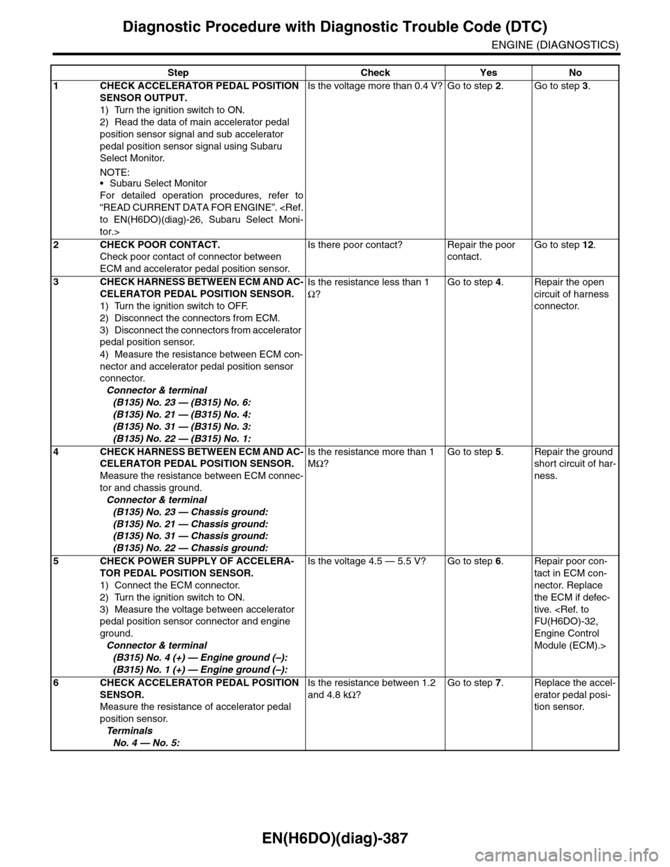
1CHECK ACCELERATOR PEDAL POSITION
SENSOR OUTPUT.
1) Turn the ignition switch to ON.
2) Read the data of main accelerator pedal
position sensor signal and sub accelerator
pedal position sensor signal using Subaru
Select Monitor.
NOTE:•Subaru Select Monitor
For detailed operation procedures, refer to
“READ CURRENT DATA FOR ENGINE”.
tor.>
Is the voltage more than 0.4 V? Go to step 2.Go to step 3.
2CHECK POOR CONTACT.
Check poor contact of connector between
ECM and accelerator pedal position sensor.
Is there poor contact? Repair the poor
contact.
Go to step 12.
3CHECK HARNESS BETWEEN ECM AND AC-
CELERATOR PEDAL POSITION SENSOR.
1) Turn the ignition switch to OFF.
2) Disconnect the connectors from ECM.
3) Disconnect the connectors from accelerator
pedal position sensor.
4) Measure the resistance between ECM con-
nector and accelerator pedal position sensor
connector.
Connector & terminal
(B135) No. 23 — (B315) No. 6:
(B135) No. 21 — (B315) No. 4:
(B135) No. 31 — (B315) No. 3:
(B135) No. 22 — (B315) No. 1:
Is the resistance less than 1
Ω?
Go to step 4.Repair the open
circuit of harness
connector.
4CHECK HARNESS BETWEEN ECM AND AC-
CELERATOR PEDAL POSITION SENSOR.
Measure the resistance between ECM connec-
tor and chassis ground.
Connector & terminal
(B135) No. 23 — Chassis ground:
(B135) No. 21 — Chassis ground:
(B135) No. 31 — Chassis ground:
(B135) No. 22 — Chassis ground:
Is the resistance more than 1
MΩ?
Go to step 5.Repair the ground
short circuit of har-
ness.
5CHECK POWER SUPPLY OF ACCELERA-
TOR PEDAL POSITION SENSOR.
1) Connect the ECM connector.
2) Turn the ignition switch to ON.
3) Measure the voltage between accelerator
pedal position sensor connector and engine
ground.
Connector & terminal
(B315) No. 4 (+) — Engine ground (–):
(B315) No. 1 (+) — Engine ground (–):
Is the voltage 4.5 — 5.5 V? Go to step 6.Repair poor con-
tact in ECM con-
nector. Replace
the ECM if defec-
tive.
Engine Control
Module (ECM).>
6CHECK ACCELERATOR PEDAL POSITION
SENSOR.
Measure the resistance of accelerator pedal
position sensor.
Te r m i n a l s
No. 4 — No. 5:
Is the resistance between 1.2
and 4.8 kΩ?
Go to step 7.Replace the accel-
erator pedal posi-
tion sensor.
Page 1549 of 2453
EN(H6DO)(diag)-388
Diagnostic Procedure with Diagnostic Trouble Code (DTC)
ENGINE (DIAGNOSTICS)
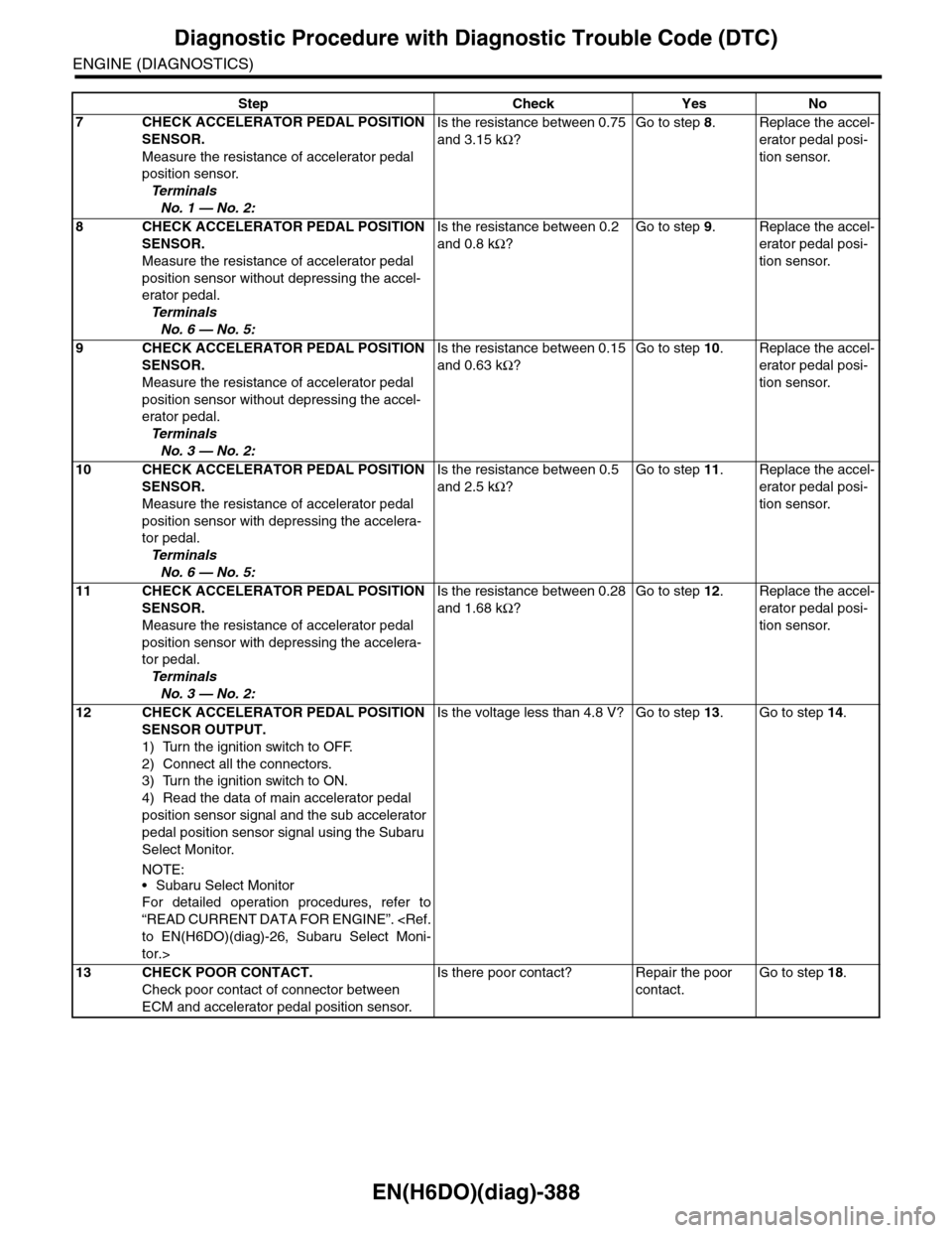
7CHECK ACCELERATOR PEDAL POSITION
SENSOR.
Measure the resistance of accelerator pedal
position sensor.
Te r m i n a l s
No. 1 — No. 2:
Is the resistance between 0.75
and 3.15 kΩ?
Go to step 8.Replace the accel-
erator pedal posi-
tion sensor.
8CHECK ACCELERATOR PEDAL POSITION
SENSOR.
Measure the resistance of accelerator pedal
position sensor without depressing the accel-
erator pedal.
Te r m i n a l s
No. 6 — No. 5:
Is the resistance between 0.2
and 0.8 kΩ?
Go to step 9.Replace the accel-
erator pedal posi-
tion sensor.
9CHECK ACCELERATOR PEDAL POSITION
SENSOR.
Measure the resistance of accelerator pedal
position sensor without depressing the accel-
erator pedal.
Te r m i n a l s
No. 3 — No. 2:
Is the resistance between 0.15
and 0.63 kΩ?
Go to step 10.Replace the accel-
erator pedal posi-
tion sensor.
10 CHECK ACCELERATOR PEDAL POSITION
SENSOR.
Measure the resistance of accelerator pedal
position sensor with depressing the accelera-
tor pedal.
Te r m i n a l s
No. 6 — No. 5:
Is the resistance between 0.5
and 2.5 kΩ?
Go to step 11.Replace the accel-
erator pedal posi-
tion sensor.
11 CHECK ACCELERATOR PEDAL POSITION
SENSOR.
Measure the resistance of accelerator pedal
position sensor with depressing the accelera-
tor pedal.
Te r m i n a l s
No. 3 — No. 2:
Is the resistance between 0.28
and 1.68 kΩ?
Go to step 12.Replace the accel-
erator pedal posi-
tion sensor.
12 CHECK ACCELERATOR PEDAL POSITION
SENSOR OUTPUT.
1) Turn the ignition switch to OFF.
2) Connect all the connectors.
3) Turn the ignition switch to ON.
4) Read the data of main accelerator pedal
position sensor signal and the sub accelerator
pedal position sensor signal using the Subaru
Select Monitor.
NOTE:
•Subaru Select Monitor
For detailed operation procedures, refer to
“READ CURRENT DATA FOR ENGINE”.
tor.>
Is the voltage less than 4.8 V? Go to step 13.Go to step 14.
13 CHECK POOR CONTACT.
Check poor contact of connector between
ECM and accelerator pedal position sensor.
Is there poor contact? Repair the poor
contact.
Go to step 18.
Step Check Yes No
Page 1553 of 2453
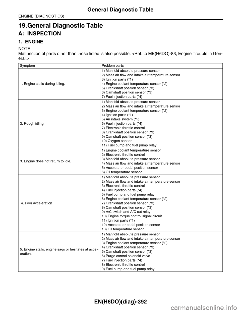
EN(H6DO)(diag)-392
General Diagnostic Table
ENGINE (DIAGNOSTICS)
19.General Diagnostic Table
A: INSPECTION
1. ENGINE
NOTE:
Malfunction of parts other than those listed is also possible.
Symptom Problem parts
1. Engine stalls during idling.
1) Manifold absolute pressure sensor
2) Mass air flow and intake air temperature sensor
3) Ignition parts (*1)
4) Engine coolant temperature sensor (*2)
5) Crankshaft position sensor (*3)
6) Camshaft position sensor (*3)
7) Fuel injection parts (*4)
2. Rough idling
1) Manifold absolute pressure sensor
2) Mass air flow and intake air temperature sensor
3) Engine coolant temperature sensor (*2)
4) Ignition parts (*1)
5) Air intake system (*5)
6) Fuel injection parts (*4)
7) Electronic throttle control
8) Crankshaft position sensor (*3)
9) Camshaft position sensor (*3)
10) Oxygen sensor
11) Fuel pump and fuel pump relay
3. Engine does not return to idle.
1) Engine coolant temperature sensor
2) Electronic throttle control
3) Manifold absolute pressure sensor
4) Mass air flow and intake air temperature sensor
5) Accelerator pedal position sensor
6) Oil temperature sensor
4. Poor acceleration
1) Manifold absolute pressure sensor
2) Mass air flow and intake air temperature sensor
3) Electronic throttle control
4) Fuel injection parts (*4)
5) Fuel pump and fuel pump relay
6) Engine coolant temperature sensor (*2)
7) Crankshaft position sensor (*3)
8) Camshaft position sensor (*3)
9) A/C switch and A/C cut relay
10) Engine torque control signal circuit
11) Ignition parts (*1)
12) Accelerator pedal position sensor
13) Oil temperature sensor
5. Engine stalls, engine sags or hesitates at accel-
eration.
1) Manifold absolute pressure sensor
2) Mass air flow and intake air temperature sensor
3) Engine coolant temperature sensor (*2)
4) Crankshaft position sensor (*3)
5) Camshaft position sensor (*3)
6) Purge control solenoid valve
7) Fuel injection parts (*4)
8) Electronic throttle control
9) Fuel pump and fuel pump relay
Page 1619 of 2453
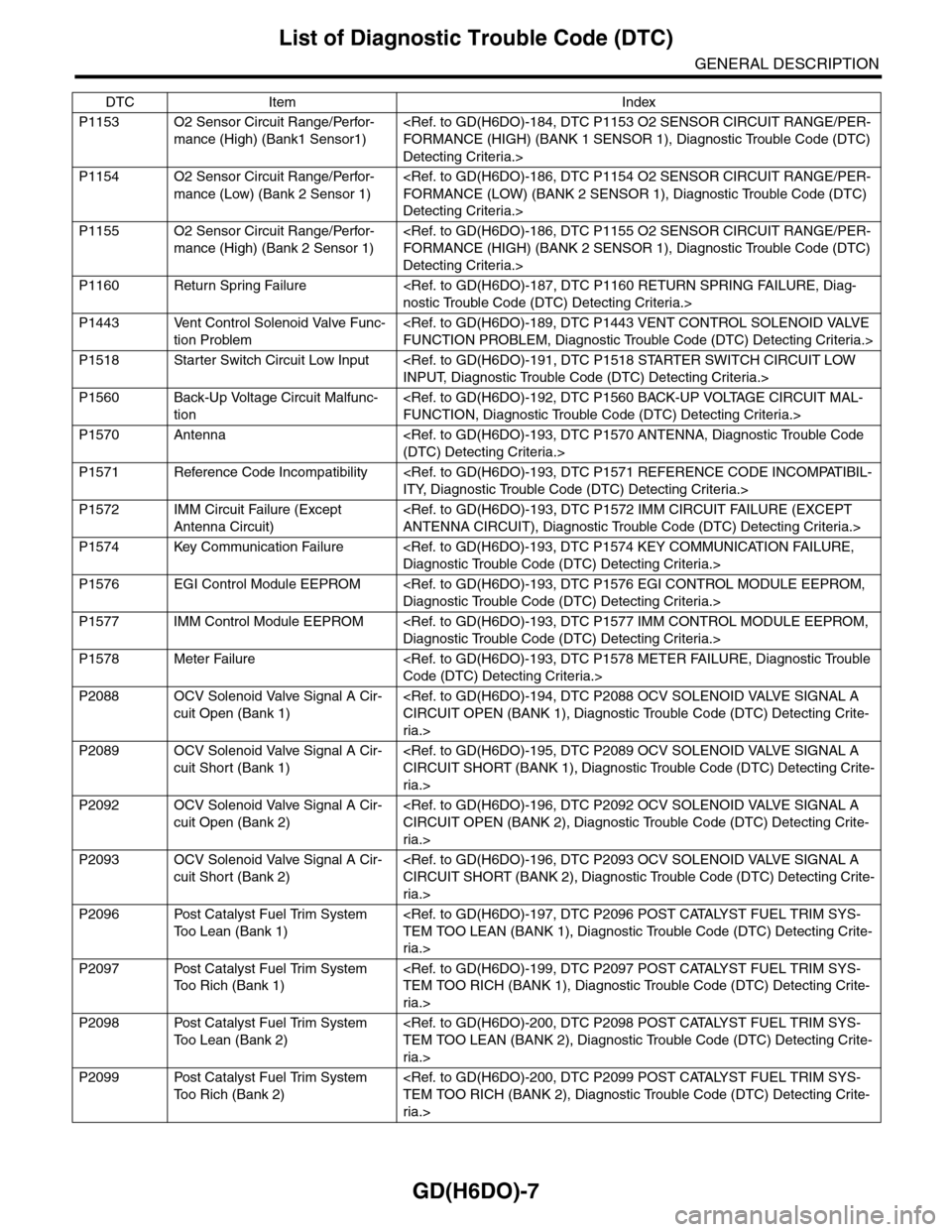
GD(H6DO)-7
List of Diagnostic Trouble Code (DTC)
GENERAL DESCRIPTION
P1153 O2 Sensor Circuit Range/Perfor-
mance (High) (Bank1 Sensor1)
Detecting Criteria.>
P1154 O2 Sensor Circuit Range/Perfor-
mance (Low) (Bank 2 Sensor 1)
Detecting Criteria.>
P1155 O2 Sensor Circuit Range/Perfor-
mance (High) (Bank 2 Sensor 1)
Detecting Criteria.>
P1160 Return Spring Failure
P1443 Vent Control Solenoid Valve Func-
tion Problem
P1518 Starter Switch Circuit Low Input
P1560 Back-Up Voltage Circuit Malfunc-
tion
P1570 Antenna
P1571 Reference Code Incompatibility
P1572 IMM Circuit Failure (Except
Antenna Circuit)
P1574 Key Communication Failure
P1576 EGI Control Module EEPROM
P1577 IMM Control Module EEPROM
P1578 Meter Failure
P2088 OCV Solenoid Valve Signal A Cir-
cuit Open (Bank 1)
ria.>
P2089 OCV Solenoid Valve Signal A Cir-
cuit Short (Bank 1)
ria.>
P2092 OCV Solenoid Valve Signal A Cir-
cuit Open (Bank 2)
ria.>
P2093 OCV Solenoid Valve Signal A Cir-
cuit Short (Bank 2)
ria.>
P2096 Post Catalyst Fuel Trim System
To o L e a n ( B a n k 1 )
ria.>
P2097 Post Catalyst Fuel Trim System
To o R i c h ( B a n k 1 )
ria.>
P2098 Post Catalyst Fuel Trim System
To o L e a n ( B a n k 2 )
ria.>
P2099 Post Catalyst Fuel Trim System
To o R i c h ( B a n k 2 )
ria.>
DTC Item Index
Page 1661 of 2453
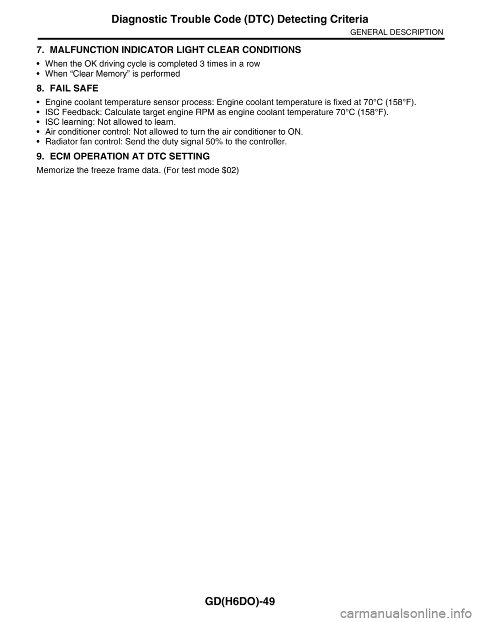
GD(H6DO)-49
Diagnostic Trouble Code (DTC) Detecting Criteria
GENERAL DESCRIPTION
7. MALFUNCTION INDICATOR LIGHT CLEAR CONDITIONS
•When the OK driving cycle is completed 3 times in a row
•When “Clear Memory” is performed
8. FAIL SAFE
•Engine coolant temperature sensor process: Engine coolant temperature is fixed at 70°C (158°F).
•ISC Feedback: Calculate target engine RPM as engine coolant temperature 70°C (158°F).
•ISC learning: Not allowed to learn.
•Air conditioner control: Not allowed to turn the air conditioner to ON.
•Radiator fan control: Send the duty signal 50% to the controller.
9. ECM OPERATION AT DTC SETTING
Memorize the freeze frame data. (For test mode $02)
Page 1663 of 2453
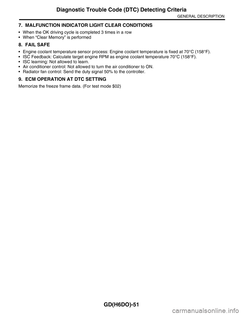
GD(H6DO)-51
Diagnostic Trouble Code (DTC) Detecting Criteria
GENERAL DESCRIPTION
7. MALFUNCTION INDICATOR LIGHT CLEAR CONDITIONS
•When the OK driving cycle is completed 3 times in a row
•When “Clear Memory” is performed
8. FAIL SAFE
•Engine coolant temperature sensor process: Engine coolant temperature is fixed at 70°C (158°F).
•ISC Feedback: Calculate target engine RPM as engine coolant temperature 70°C (158°F).
•ISC learning: Not allowed to learn.
•Air conditioner control: Not allowed to turn the air conditioner to ON.
•Radiator fan control: Send the duty signal 50% to the controller.
9. ECM OPERATION AT DTC SETTING
Memorize the freeze frame data. (For test mode $02)