Page 292 of 2453
EI-50
Roof Trim
EXTERIOR/INTERIOR TRIM
23.Roof Trim
A: REMOVAL
1) Disconnect the ground cable from battery.
2) Remove the spot map light.
MOVAL, Spot Map Light.>
3) Remove the room light or rear entertainment
(model with rear entertainment system).
LI-30, REMOVAL, Room Light.>
4) Remove the sun visor.
AL, Sun Visor.>
5) Remove the assist grip.
AL, Assist Grip.>
6) Remove the front pillar upper trim and center pil-
lar upper trim.
Trim.>
7) Remove the rear quarter upper trim.
45, REMOVAL, Rear Quarter Trim.>
8) Remove the sunroof opening trim.
9) Remove the clips and each harness, pull out the
rear center seat belt, and remove the roof trim.
B: INSTALLATION
Install in the reverse order of removal.
EI-00501
EI-01354
Page 300 of 2453
GW-5
General Description
GLASS/WINDOWS/MIRRORS
4. MIRROR
B: CAUTION
•When electrical connectors are disconnected, always conduct an operational check after connecting them
again.
•Avoid impact and damage to the glass.
C: PREPARATION TOOL
1. GENERAL TOOL
(1) Outer mirror (4) Side turn signal lightTightening torque: N·m (kgf-m, ft-lb)
(2) Mirror (5) Rearview mirrorT: 2 (0.2, 1.5)
(3) Scalp cap (6) Mount
TOOL NAME REMARKS
Circuit tester Used for checking voltage and continuity.
Piano wire Used for removing the window glass.
Windshield glass knife Used for removing the window glass.
TO RX® T20Used for removing and installing the rearview mirror.
GW-00476
(5)
(6)
(2)
(3)
(4)
(1)
T
Page 315 of 2453

GW-20
Windshield Glass
GLASS/WINDOWS/MIRRORS
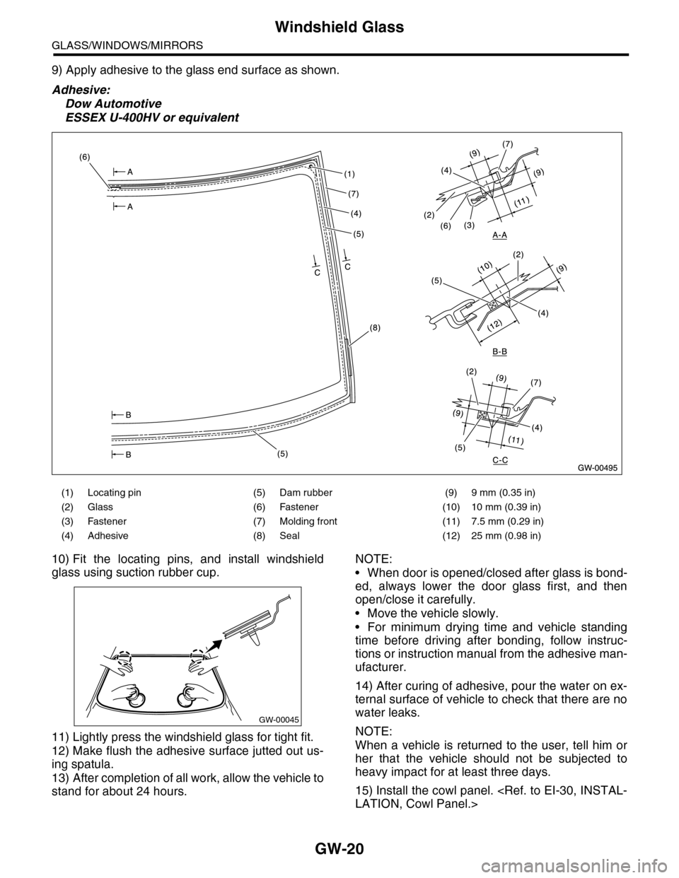
9) Apply adhesive to the glass end surface as shown.
Adhesive:
Dow Automotive
ESSEX U-400HV or equivalent
10) Fit the locating pins, and install windshield
glass using suction rubber cup.
11) Lightly press the windshield glass for tight fit.
12) Make flush the adhesive surface jutted out us-
ing spatula.
13) After completion of all work, allow the vehicle to
stand for about 24 hours.
NOTE:
•When door is opened/closed after glass is bond-
ed, always lower the door glass first, and then
open/close it carefully.
•Move the vehicle slowly.
•For minimum drying time and vehicle standing
time before driving after bonding, follow instruc-
tions or instruction manual from the adhesive man-
ufacturer.
14) After curing of adhesive, pour the water on ex-
ternal surface of vehicle to check that there are no
water leaks.
NOTE:
When a vehicle is returned to the user, tell him or
her that the vehicle should not be subjected to
heavy impact for at least three days.
15) Install the cowl panel.
LATION, Cowl Panel.>
(1) Locating pin (5) Dam rubber (9) 9 mm (0.35 in)
(2) Glass (6) Fastener (10) 10 mm (0.39 in)
(3) Fastener (7) Molding front (11) 7.5 mm (0.29 in)
(4) Adhesive (8) Seal (12) 25 mm (0.98 in)
GW-00045
Page 317 of 2453
GW-22
Rear Gate Glass
GLASS/WINDOWS/MIRRORS
15.Rear Gate Glass
A: REMOVAL
1) Remove the rear wiper motor.
REMOVAL, Rear Wiper Motor.>
2) Disconnect the electrical connectors from rear
defogger terminal.
3) Remove the glass in the same procedure as for
windshield glass.
Windshield Glass.>
B: INSTALLATION
1) Mount the fastener on the body.
2) Install the dam rubber.
3) Cut off the cartridge nozzle tip as shown and set
it in sealant gun.
4) Apply adhesive in the same procedure as for
windshield glass.
TION, Windshield Glass.>
5) Insert the glass clip pin into rear gate hole, push
on the area around the clip pin to secure it, and
then push lightly all around the area to seal it.
(1) Glass
(2) Spacer
(3) Adhesive
(4) Fastener
(5) 4 mm (0.15 in)
(6) 8 mm (0.31 in)
(7) 10 mm (0.39 in)
(8) 5.5 mm (0.22 in)
Page 350 of 2453

AC-24
Refrigerant Leak Check
HVAC SYSTEM (HEATER, VENTILATOR AND A/C)
5. Refrigerant Leak Check
A: INSPECTION
1) At engine speed below 1500rpm, operate the A/
C system for approx. 10 minutes, and confirm that
the high-side pressure shows at least 690 kPa
(7.03 kg/cm2, 100 psi). Then stop the engine to
start the leak test.
2) Starting from the connection between high-pres-
sure pipe and evaporator, check the system for
leaks along the high-pressure side through the
compressor. The following items must be checked
thoroughly.
3) Check the joint and seam between pressure
switch (dual switch) and high-pressure pipe.
4) Check the connections between condenser and
pipes, and welded joints on the condenser.
The leak tester may detect the oil on the condenser
fins as a leak.
5) Check the joint between compressor and hoses.
6) Check the machined area of the compressor and
other joints on the compressor.
7) Check the compressor shaft seal at the area
near the center of compressor clutch pulley.
Some shaft seals show a slight amount of leakage,
about 3 g (0.1 oz) per year. This is not a problem.
8) Starting from the connection between low-pres-
sure pipe and evaporator, check the system for
leakage along the low-pressure side through the
compressor. The following items must be checked
thoroughly.
•Connection between 2 parts
•Connection between pipe and plate
•Connection between pipes
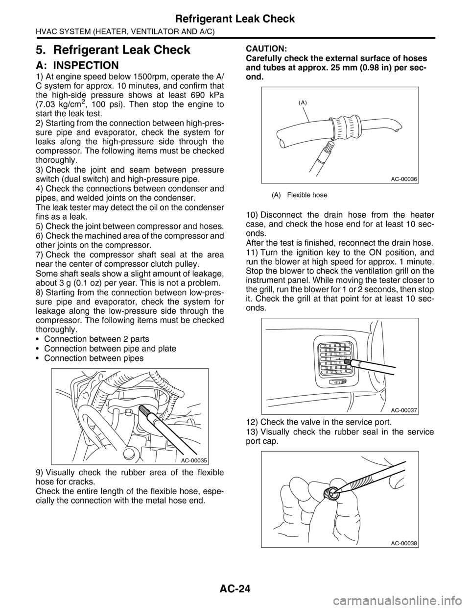
9) Visually check the rubber area of the flexible
hose for cracks.
Check the entire length of the flexible hose, espe-
cially the connection with the metal hose end.
CAUTION:
Carefully check the external surface of hoses
and tubes at approx. 25 mm (0.98 in) per sec-
ond.
10) Disconnect the drain hose from the heater
case, and check the hose end for at least 10 sec-
onds.
After the test is finished, reconnect the drain hose.
11) Turn the ignition key to the ON position, and
run the blower at high speed for approx. 1 minute.
Stop the blower to check the ventilation grill on the
instrument panel. While moving the tester closer to
the grill, run the blower for 1 or 2 seconds, then stop
it. Check the grill at that point for at least 10 sec-
onds.
12) Check the valve in the service port.
13) Visually check the rubber seal in the service
port cap.
AC-00035
(A) Flexible hose
AC-00036
(A)
AC-00037
AC-00038
Page 381 of 2453

AC(diag)-4
General Description
HVAC SYSTEM (AUTO A/C) (DIAGNOSTICS)
4. CONTROL SWITCHES
Start the engine and warm-up completely.
1) Inspection using switches
2) Compressor operation inspection
3) Inspection of illumination control
No. Point to check Switch operation Judgment standard
1OFF switch Press the OFF switch.
Setting temperature display goes out.
•Blower fan: OFF
•Inlet opening: FRESH
•Compressor: OFF
2
AU TO sw it c h, d r iver ’s
side temperature con-
trol dial and passen-
ger’s side temperature
control dial
1) Press the AUTO switch.
2) Turn the temperature control dial to the left
fully, and set to 18°C (65°F) (maximum cool posi-
tion).
AU TO di sp l ay i l lu mi n at e s.
•Outlet air temperature: COOL
•Blower fan: HI (AUTO)
•Outlet opening: FACE
•Inlet opening: AUTO
•Compressor: AUTO
3) Turn the temperature control dial to the right
slowly, and change the setting from 18°C (64°F)
(maximum cool position) to 32°C (85°F).
•Outlet air temperature: COOL → HOT
•Blower fan: AUTO
•Outlet opening: FACE → B/L → FOOTHEAT
•Inlet opening: AUTO
•Compressor: AUTO
4) Turn the temperature control dial to the right
fully, and set to 32°C (85°F) (maximum hot posi-
tion).
•Outlet air temperature: HOT
•Blower fan: HI (AUTO)
•Outlet opening: HEAT
•Inlet opening: FRESH (AUTO)
•Compressor: AUTO
3Defroster switch Press the defroster switch.
Defroster switch indicator illuminates.
•Outlet air temperature: AUTO
•Blower fan: AUTO
•Outlet opening: DEF
•Inlet opening: FRESH
•Compressor: ON
4FRESH/RECIRC
switchPress the FRESH/RECIRC switch.
Inlet opening switches RECIRC → FRESH or
FRESH → RECIRC each time pressing the
switch.
5MODE switch Press the MODE switch.Outlet opening switches FACE → B / L → HEAT
→ D/H each time pressing the switch.
6FAN switch Turn the FAN switch.
Blower fan switches OFF → LO → M1 → M2
→ M3 → M4 → HI each time turning the
switch and it switches in reverse order when
turned backward.
No. Point to check Switch operation Judgment standard
1Compressor1) Turn the A/C switch to ON.
2) Set the FAN switch between LO and HI.Compressor: ON
No. Point to check Switch operation Judgment standard
1Illumination Turn the lighting switch to ON. Illumination comes on.
Page 382 of 2453
AC(diag)-5
General Description
HVAC SYSTEM (AUTO A/C) (DIAGNOSTICS)
4) Inspection of the rear cooler switch
5) Inspection of rear cooler
6) Inspection of illumination control
No. Point to check Switch operation Judgment standard
1FAN switch Turn the FAN switch.
Blower fan switches OFF → LO → ML → MH
→ HI each time turning the switch and it
switches in reverse order when turned back-
ward.
No. Point to check Switch operation Judgment standard
1Roof grill Turn the FAN switch.
Fr on t A / C O N ( co mp r es so r op e rat i ng ) : COOL
Fr on t A / C O FF ( co mp r e ss or n ot o pe ra t in g) :
Blower ON
No. Point to check Switch operation Judgment standard
1Illumination Turn the lighting switch to ON. Illumination comes on.
Page 414 of 2453
AC(diag)-37
Diagnostic Procedure for Sensors
HVAC SYSTEM (AUTO A/C) (DIAGNOSTICS)
D: SUNLOAD SENSOR
TROUBLE SYMPTOM:
•Sensor identifies that sunlight is at maximum. Then, A/C system is controlled to COOL side.
•Sensor identifies that sunlight is at minimum. Then, A/C system is controlled to HOT side.
NOTE:
When the sunload sensor check is performed indoors or in the shade, it could be diagnosed as having an
open circuit. Always check the sunload sensor with the sun shining on it.
WIRING DIAGRAM:
AC-00832
A:B282
12345678910 11 12 13 14 15 16
i51
A:B282
A8A6
21
i3
B38
i51
12
AUTO A/C CONTROL MODULE
32
1234 5678910 11 12 13 14 15 16 17 18 19 20
B38
SUNLOADSENSOR