2009 SUBARU TRIBECA coolant temperature
[x] Cancel search: coolant temperaturePage 1734 of 2453
GD(H6DO)-122
Diagnostic Trouble Code (DTC) Detecting Criteria
GENERAL DESCRIPTION
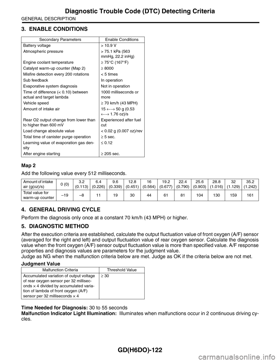
3. ENABLE CONDITIONS
Map 2
Add the following value every 512 milliseconds.
4. GENERAL DRIVING CYCLE
Perform the diagnosis only once at a constant 70 km/h (43 MPH) or higher.
5. DIAGNOSTIC METHOD
After the execution criteria are established, calculate the output fluctuation value of front oxygen (A/F) sensor
(averaged for the right and left) and output fluctuation value of rear oxygen sensor. Calculate the diagnosis
value when the front oxygen (A/F) sensor output fluctuation value is more than specified value. A/F response
properties and diagnosis values are parameters for the judgment value.
Judge as NG when the malfunction criteria below are met. Judge as OK if the criteria below are not met.
Time Needed for Diagnosis: 30 to 55 seconds
Malfunction Indicator Light Illumination: Illuminates when malfunctions occur in 2 continuous driving cy-
cles.
Secondary Parameters Enable Conditions
Battery voltage > 10.9 V
Atmospheric pressure > 75.1 kPa (563
mmHg, 22.2 inHg)
Engine coolant temperature≥ 75°C (167°F)
Catalyst warm-up counter (Map 2)≥ 8000
Misfire detection every 200 rotations < 5 times
Sub feedback In operation
Evaporative system diagnosis Not in operation
Time of difference (< 0.10) between
actual and target lambda
1000 milliseconds or
more
Ve h i c l e s p e e d≥ 70 km/h (43 MPH)
Amount of intake air 15 ←→ 50 g (0.53
←→ 1.76 oz)/s
Rear O2 output change from lower than
to higher than 600 mV
Experienced after fuel
cut
Load change absolute value < 0.02 g (0.007 oz)/rev
To t a l t i m e o f c a n i s t e r p u r g e o p e r a t i o n≥ 5 sec.
Learning value of evaporation gas den-
sity
≤ 0.12
After engine starting≥ 205 sec.
Amount of intake
air (g(oz)/s)0 (0)3.2
(0.113)
6.4
(0.226)
9.6
(0.339)
12.8
(0.451)
16
(0.564)
19.2
(0.677)
22.4
(0.790)
25.6
(0.903)
28.8
(1.016)
32
(1.129)
35.2
(1.242)
To t a l v a l u e f o r
warm-up counter–19 –8 11 19 30 44 61 81 104 130 159 161
Judgment Value
Malfunction Criteria Threshold Value
Accumulated variation of output voltage
of rear oxygen sensor per 32 millisec-
onds × 4 divided by accumulated varia-
tion of lambda of front oxygen (A/F)
sensor per 32 milliseconds × 4
≥ 30
Page 1772 of 2453
GD(H6DO)-160
Diagnostic Trouble Code (DTC) Detecting Criteria
GENERAL DESCRIPTION
CQ:DTC P0483 COOLING FAN RATIONALITY CHECK
1. OUTLINE OF DIAGNOSIS
Detect the function abnormality of the radiator fan.
Judge as NG when the engine coolant temperature slowly decreases even when the radiator fan is rotating.
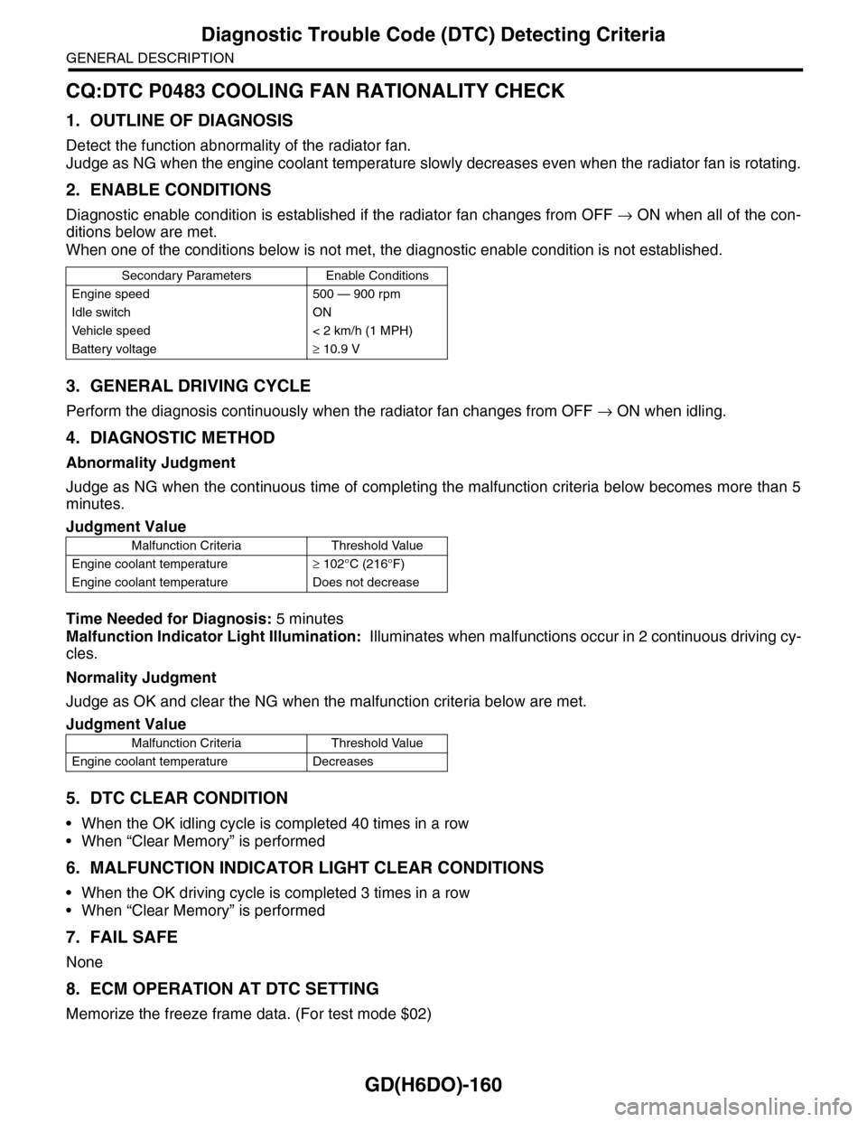
2. ENABLE CONDITIONS
Diagnostic enable condition is established if the radiator fan changes from OFF → ON when all of the con-
ditions below are met.
When one of the conditions below is not met, the diagnostic enable condition is not established.
3. GENERAL DRIVING CYCLE
Perform the diagnosis continuously when the radiator fan changes from OFF → ON when idling.
4. DIAGNOSTIC METHOD
Abnormality Judgment
Judge as NG when the continuous time of completing the malfunction criteria below becomes more than 5
minutes.
Time Needed for Diagnosis: 5 minutes
Malfunction Indicator Light Illumination: Illuminates when malfunctions occur in 2 continuous driving cy-
cles.
Normality Judgment
Judge as OK and clear the NG when the malfunction criteria below are met.
5. DTC CLEAR CONDITION
•When the OK idling cycle is completed 40 times in a row
•When “Clear Memory” is performed
6. MALFUNCTION INDICATOR LIGHT CLEAR CONDITIONS
•When the OK driving cycle is completed 3 times in a row
•When “Clear Memory” is performed
7. FAIL SAFE
None
8. ECM OPERATION AT DTC SETTING
Memorize the freeze frame data. (For test mode $02)
Secondary Parameters Enable Conditions
Engine speed 500 — 900 rpm
Idle switch ON
Ve h i c l e s p e e d < 2 k m / h ( 1 M P H )
Battery voltage≥ 10.9 V
Judgment Value
Malfunction Criteria Threshold Value
Engine coolant temperature≥ 102°C (216°F)
Engine coolant temperature Does not decrease
Judgment Value
Malfunction Criteria Threshold Value
Engine coolant temperature Decreases
Page 1775 of 2453
GD(H6DO)-163
Diagnostic Trouble Code (DTC) Detecting Criteria
GENERAL DESCRIPTION
CS:DTC P0506 IDLE CONTROL SYSTEM RPM LOWER THAN EXPECTED
1. OUTLINE OF DIAGNOSIS
Detect the malfunction that actual engine rpm is not close to target engine rpm during idling. Judge as NG
when actual engine RPM is not close to target engine RPM during idling.
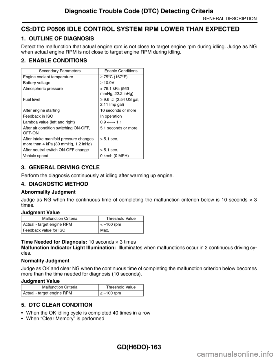
2. ENABLE CONDITIONS
3. GENERAL DRIVING CYCLE
Perform the diagnosis continuously at idling after warming up engine.
4. DIAGNOSTIC METHOD
Abnormality Judgment
Judge as NG when the continuous time of completing the malfunction criterion below is 10 seconds × 3
times.
Time Needed for Diagnosis: 10 seconds × 3 times
Malfunction Indicator Light Illumination: Illuminates when malfunctions occur in 2 continuous driving cy-
cles.
Normality Judgment
Judge as OK and clear NG when the continuous time of completing the malfunction criterion below becomes
more than the time needed for diagnosis (10 seconds).
5. DTC CLEAR CONDITION
•When the OK idling cycle is completed 40 times in a row
•When “Clear Memory” is performed
Secondary Parameters Enable Conditions
Engine coolant temperature≥ 75°C (167°F)
Battery voltage≥ 10.9V
Atmospheric pressure > 75.1 kPa (563
mmHg, 22.2 inHg)
Fuel level≥ 9.6 2 (2.54 US gal,
2.11 Imp gal)
After engine starting 10 seconds or more
Feedback in ISC In operation
Lambda value (left and right) 0.9 ←→ 1.1
After air condition switching ON-OFF,
OFF-ON
5.1 seconds or more
After intake manifold pressure changes
more than 4 kPa (30 mmHg, 1.2 inHg)
> 5.1 sec.
After neutral switch ON-OFF change > 5.1 sec.
Ve h i c l e s p e e d 0 k m / h ( 0 M P H )
Judgment Value
Malfunction Criteria Threshold Value
Actual - target engine RPM < –100 rpm
Feedback value for ISC Max.
Judgment Value
Malfunction Criteria Threshold Value
Actual - target engine RPM≥ –100 rpm
Page 1777 of 2453
GD(H6DO)-165
Diagnostic Trouble Code (DTC) Detecting Criteria
GENERAL DESCRIPTION
CT:DTC P0507 IDLE CONTROL SYSTEM RPM HIGHER THAN EXPECTED
1. OUTLINE OF DIAGNOSIS
Detect the malfunction that actual engine rpm is not close to target engine rpm during idling. Judge as NG
when actual engine RPM is not close to target engine RPM during idling.
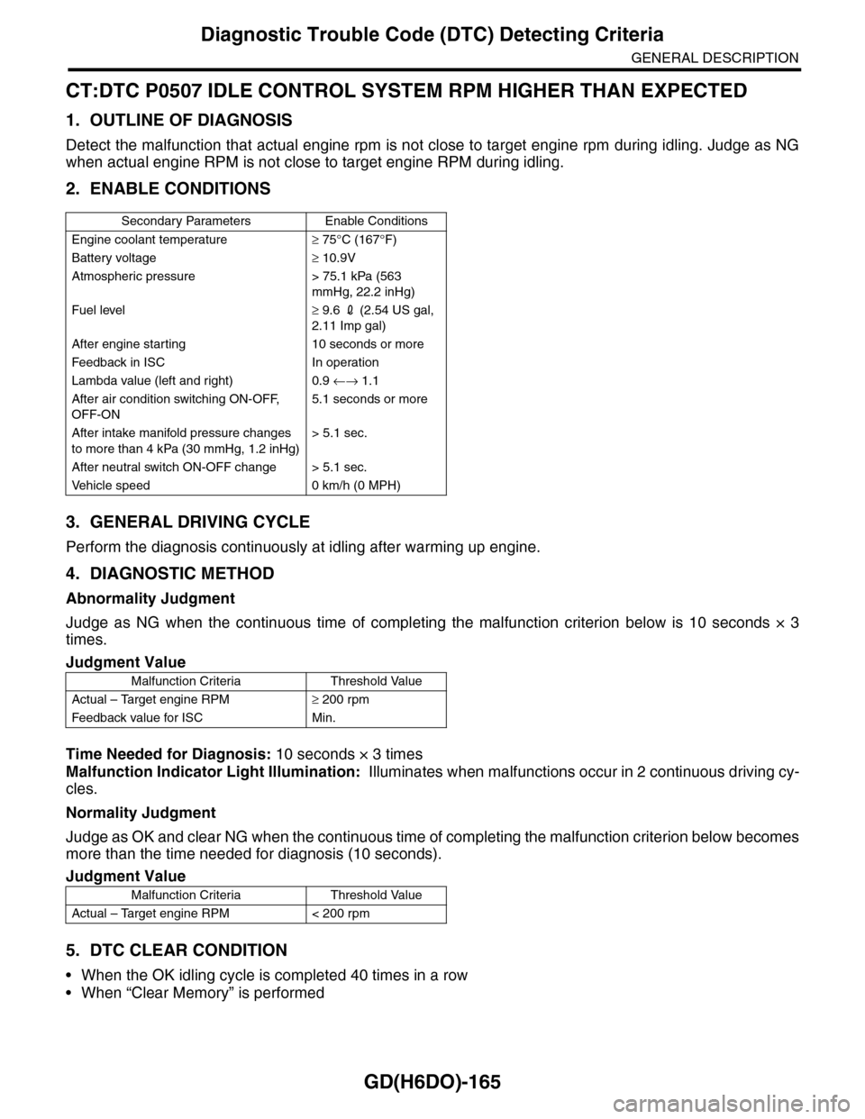
2. ENABLE CONDITIONS
3. GENERAL DRIVING CYCLE
Perform the diagnosis continuously at idling after warming up engine.
4. DIAGNOSTIC METHOD
Abnormality Judgment
Judge as NG when the continuous time of completing the malfunction criterion below is 10 seconds × 3
times.
Time Needed for Diagnosis: 10 seconds × 3 times
Malfunction Indicator Light Illumination: Illuminates when malfunctions occur in 2 continuous driving cy-
cles.
Normality Judgment
Judge as OK and clear NG when the continuous time of completing the malfunction criterion below becomes
more than the time needed for diagnosis (10 seconds).
5. DTC CLEAR CONDITION
•When the OK idling cycle is completed 40 times in a row
•When “Clear Memory” is performed
Secondary Parameters Enable Conditions
Engine coolant temperature≥ 75°C (167°F)
Battery voltage≥ 10.9V
Atmospheric pressure > 75.1 kPa (563
mmHg, 22.2 inHg)
Fuel level≥ 9.6 2 (2.54 US gal,
2.11 Imp gal)
After engine starting 10 seconds or more
Feedback in ISC In operation
Lambda value (left and right) 0.9 ←→ 1.1
After air condition switching ON-OFF,
OFF-ON
5.1 seconds or more
After intake manifold pressure changes
to more than 4 kPa (30 mmHg, 1.2 inHg)
> 5.1 sec.
After neutral switch ON-OFF change > 5.1 sec.
Ve h i c l e s p e e d 0 k m / h ( 0 M P H )
Judgment Value
Malfunction Criteria Threshold Value
Actual – Target engine RPM≥ 200 rpm
Feedback value for ISC Min.
Judgment Value
Malfunction Criteria Threshold Value
Actual – Target engine RPM < 200 rpm
Page 1794 of 2453
GD(H6DO)-182
Diagnostic Trouble Code (DTC) Detecting Criteria
GENERAL DESCRIPTION
DF:DTC P1152 O2 SENSOR CIRCUIT RANGE/PERFORMANCE (LOW) (BANK 1
SENSOR 1)
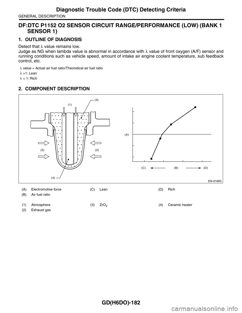
1. OUTLINE OF DIAGNOSIS
Detect that λ value remains low.
Judge as NG when lambda value is abnormal in accordance with λ value of front oxygen (A/F) sensor and
running conditions such as vehicle speed, amount of intake air engine coolant temperature, sub feedback
control, etc.
2. COMPONENT DESCRIPTION
λ value = Actual air fuel ratio/Theoretical air fuel ratio
λ >1: Lean
λ < 1: Rich
(A) Electromotive force (C) Lean (D) Rich
(B) Air fuel ratio
(1) Atmosphere (3) ZrO2(4) Ceramic heater
(2) Exhaust gas
(1)
(2)
(4)
(2)
(3)
EN-01693
(C) (B) (D)
(A)
Page 1795 of 2453
GD(H6DO)-183
Diagnostic Trouble Code (DTC) Detecting Criteria
GENERAL DESCRIPTION
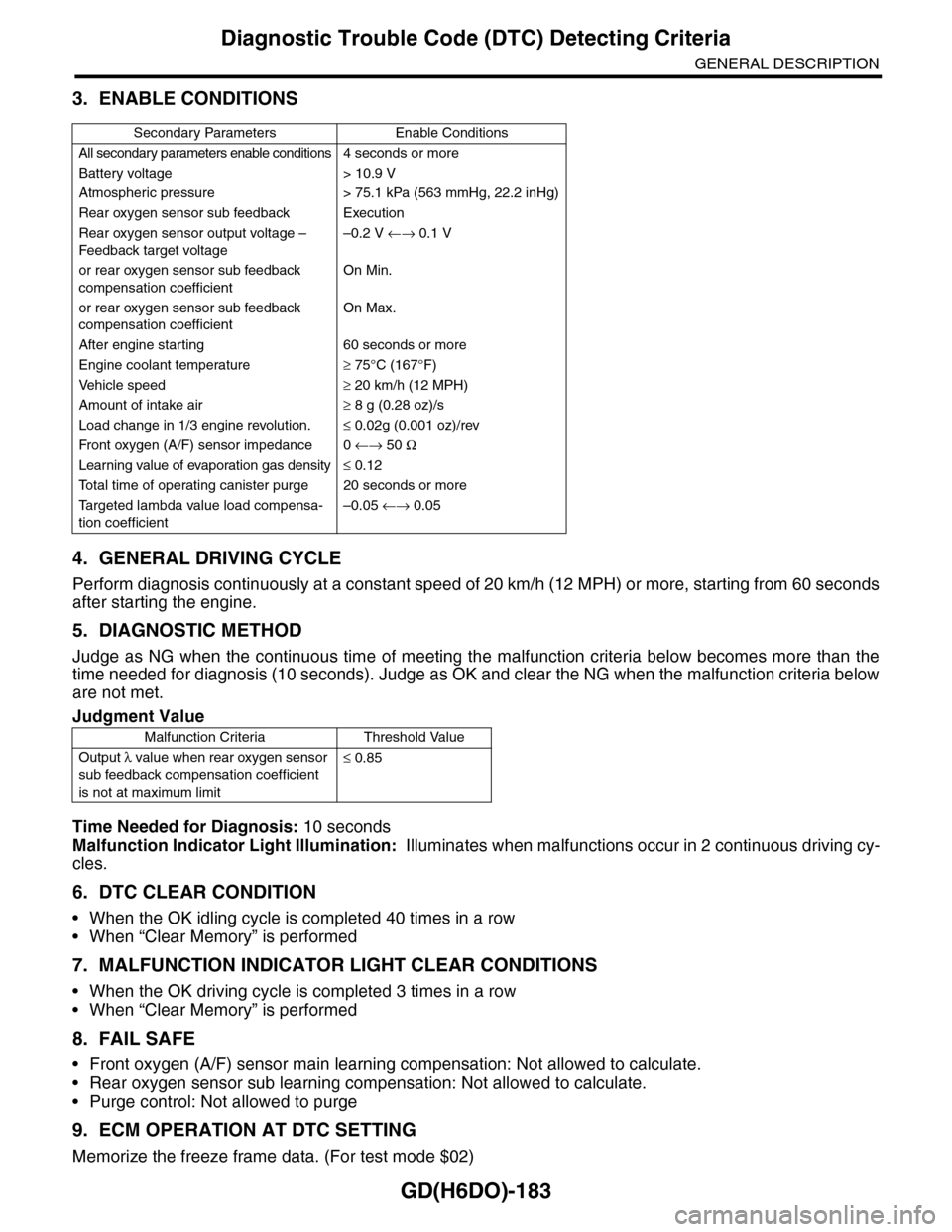
3. ENABLE CONDITIONS
4. GENERAL DRIVING CYCLE
Perform diagnosis continuously at a constant speed of 20 km/h (12 MPH) or more, starting from 60 seconds
after starting the engine.
5. DIAGNOSTIC METHOD
Judge as NG when the continuous time of meeting the malfunction criteria below becomes more than the
time needed for diagnosis (10 seconds). Judge as OK and clear the NG when the malfunction criteria below
are not met.
Time Needed for Diagnosis: 10 seconds
Malfunction Indicator Light Illumination: Illuminates when malfunctions occur in 2 continuous driving cy-
cles.
6. DTC CLEAR CONDITION
•When the OK idling cycle is completed 40 times in a row
•When “Clear Memory” is performed
7. MALFUNCTION INDICATOR LIGHT CLEAR CONDITIONS
•When the OK driving cycle is completed 3 times in a row
•When “Clear Memory” is performed
8. FAIL SAFE
•Front oxygen (A/F) sensor main learning compensation: Not allowed to calculate.
•Rear oxygen sensor sub learning compensation: Not allowed to calculate.
•Purge control: Not allowed to purge
9. ECM OPERATION AT DTC SETTING
Memorize the freeze frame data. (For test mode $02)
Secondary Parameters Enable Conditions
All secondary parameters enable conditions4 seconds or more
Battery voltage > 10.9 V
Atmospheric pressure > 75.1 kPa (563 mmHg, 22.2 inHg)
Rear oxygen sensor sub feedback Execution
Rear oxygen sensor output voltage –
Feedback target voltage
–0.2 V ←→ 0.1 V
or rear oxygen sensor sub feedback
compensation coefficient
On Min.
or rear oxygen sensor sub feedback
compensation coefficient
On Max.
After engine starting 60 seconds or more
Engine coolant temperature≥ 75°C (167°F)
Ve h i c l e s p e e d≥ 20 km/h (12 MPH)
Amount of intake air≥ 8 g (0.28 oz)/s
Load change in 1/3 engine revolution.≤ 0.02g (0.001 oz)/rev
Fr o nt ox yg e n ( A / F) s en so r im pe d an c e 0 ←→ 50 Ω
Learning value of evaporation gas density≤ 0.12
To t a l t i m e o f o p e r a t i n g c a n i s t e r p u r g e 2 0 s e c o n d s o r m o r e
Ta r g e t e d l a m b d a v a l u e l o a d c o m p e n s a -
tion coefficient
–0.05 ←→ 0.05
Judgment Value
Malfunction Criteria Threshold Value
Output λ value when rear oxygen sensor
sub feedback compensation coefficient
is not at maximum limit
≤ 0.85
Page 1796 of 2453
GD(H6DO)-184
Diagnostic Trouble Code (DTC) Detecting Criteria
GENERAL DESCRIPTION
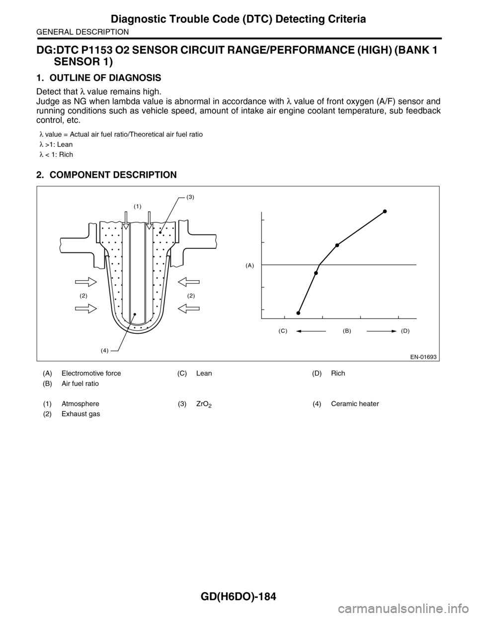
DG:DTC P1153 O2 SENSOR CIRCUIT RANGE/PERFORMANCE (HIGH) (BANK 1
SENSOR 1)
1. OUTLINE OF DIAGNOSIS
Detect that λ value remains high.
Judge as NG when lambda value is abnormal in accordance with λ value of front oxygen (A/F) sensor and
running conditions such as vehicle speed, amount of intake air engine coolant temperature, sub feedback
control, etc.
2. COMPONENT DESCRIPTION
λ value = Actual air fuel ratio/Theoretical air fuel ratio
λ >1: Lean
λ < 1: Rich
(A) Electromotive force (C) Lean (D) Rich
(B) Air fuel ratio
(1) Atmosphere (3) ZrO2(4) Ceramic heater
(2) Exhaust gas
(1)
(2)
(4)
(2)
(3)
EN-01693
(C) (B) (D)
(A)
Page 1797 of 2453
GD(H6DO)-185
Diagnostic Trouble Code (DTC) Detecting Criteria
GENERAL DESCRIPTION
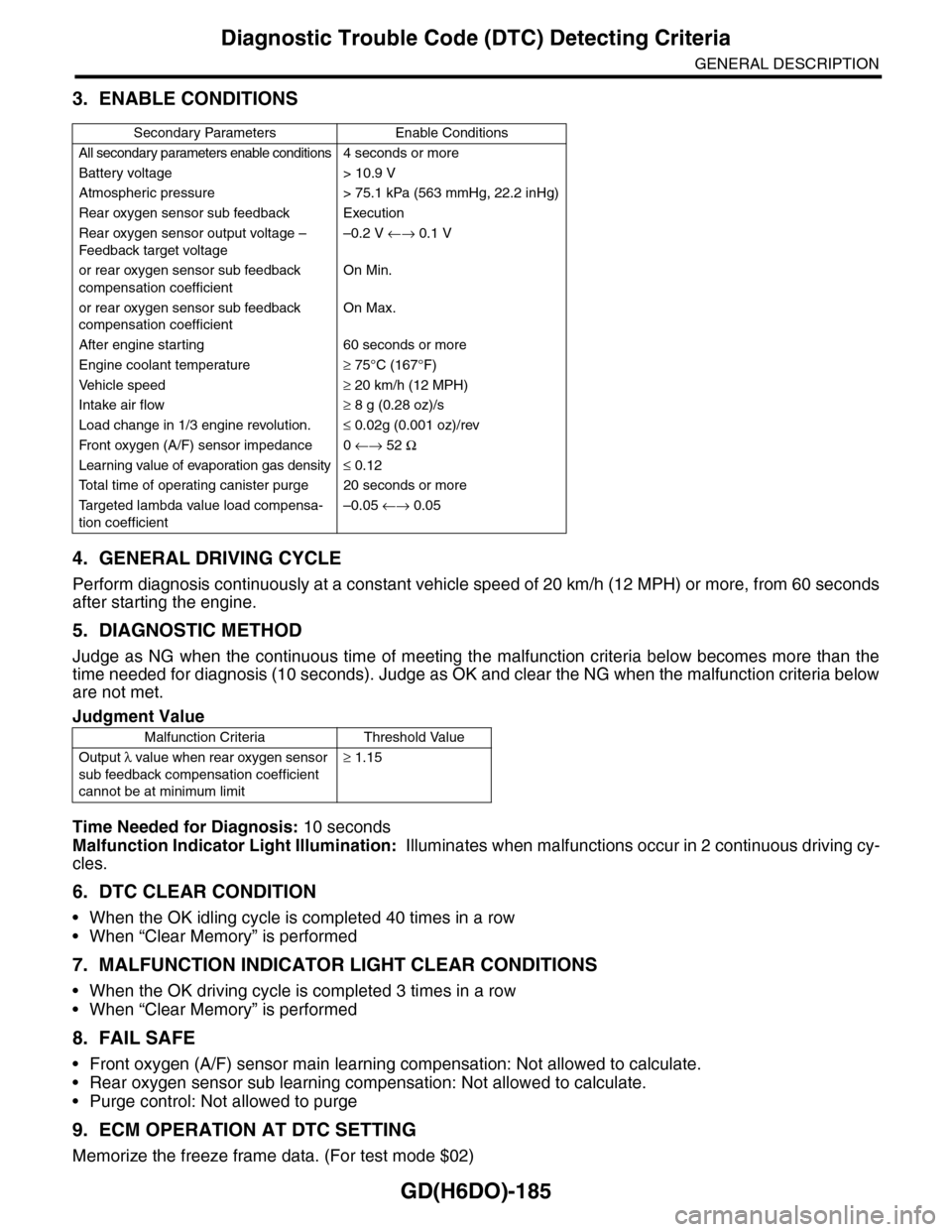
3. ENABLE CONDITIONS
4. GENERAL DRIVING CYCLE
Perform diagnosis continuously at a constant vehicle speed of 20 km/h (12 MPH) or more, from 60 seconds
after starting the engine.
5. DIAGNOSTIC METHOD
Judge as NG when the continuous time of meeting the malfunction criteria below becomes more than the
time needed for diagnosis (10 seconds). Judge as OK and clear the NG when the malfunction criteria below
are not met.
Time Needed for Diagnosis: 10 seconds
Malfunction Indicator Light Illumination: Illuminates when malfunctions occur in 2 continuous driving cy-
cles.
6. DTC CLEAR CONDITION
•When the OK idling cycle is completed 40 times in a row
•When “Clear Memory” is performed
7. MALFUNCTION INDICATOR LIGHT CLEAR CONDITIONS
•When the OK driving cycle is completed 3 times in a row
•When “Clear Memory” is performed
8. FAIL SAFE
•Front oxygen (A/F) sensor main learning compensation: Not allowed to calculate.
•Rear oxygen sensor sub learning compensation: Not allowed to calculate.
•Purge control: Not allowed to purge
9. ECM OPERATION AT DTC SETTING
Memorize the freeze frame data. (For test mode $02)
Secondary Parameters Enable Conditions
All secondary parameters enable conditions4 seconds or more
Battery voltage > 10.9 V
Atmospheric pressure > 75.1 kPa (563 mmHg, 22.2 inHg)
Rear oxygen sensor sub feedback Execution
Rear oxygen sensor output voltage –
Feedback target voltage
–0.2 V ←→ 0.1 V
or rear oxygen sensor sub feedback
compensation coefficient
On Min.
or rear oxygen sensor sub feedback
compensation coefficient
On Max.
After engine starting 60 seconds or more
Engine coolant temperature≥ 75°C (167°F)
Ve h i c l e s p e e d≥ 20 km/h (12 MPH)
Intake air flow≥ 8 g (0.28 oz)/s
Load change in 1/3 engine revolution.≤ 0.02g (0.001 oz)/rev
Fr o nt ox yg e n ( A / F) s en so r im pe d an c e 0 ←→ 52 Ω
Learning value of evaporation gas density≤ 0.12
To t a l t i m e o f o p e r a t i n g c a n i s t e r p u r g e 2 0 s e c o n d s o r m o r e
Ta r g e t e d l a m b d a v a l u e l o a d c o m p e n s a -
tion coefficient
–0.05 ←→ 0.05
Judgment Value
Malfunction Criteria Threshold Value
Output λ value when rear oxygen sensor
sub feedback compensation coefficient
cannot be at minimum limit
≥ 1.15