2009 SUBARU TRIBECA coolant temperature
[x] Cancel search: coolant temperaturePage 1906 of 2453
ME(H6DO)-40
Preparation for Overhaul
MECHANICAL
12.Preparation for Overhaul
A: REMOVAL
1) Remove the engine assembly from the body.
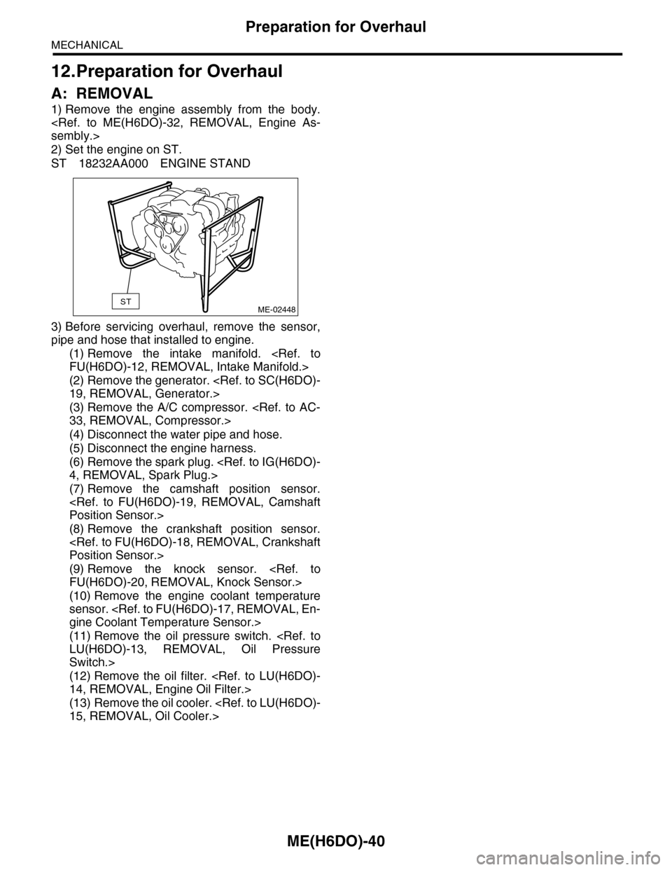
2) Set the engine on ST.
ST 18232AA000 ENGINE STAND
3) Before servicing overhaul, remove the sensor,
pipe and hose that installed to engine.
(1) Remove the intake manifold.
(2) Remove the generator.
(3) Remove the A/C compressor.
(4) Disconnect the water pipe and hose.
(5) Disconnect the engine harness.
(6) Remove the spark plug.
(7) Remove the camshaft position sensor.
(8) Remove the crankshaft position sensor.
(9) Remove the knock sensor.
(10) Remove the engine coolant temperature
sensor.
(11) Remove the oil pressure switch.
Switch.>
(12) Remove the oil filter.
(13) Remove the oil cooler.
STME-02448
Page 1996 of 2453
PM-13
Cooling System
PERIODIC MAINTENANCE SERVICES
9. Cooling System
A: INSPECTION
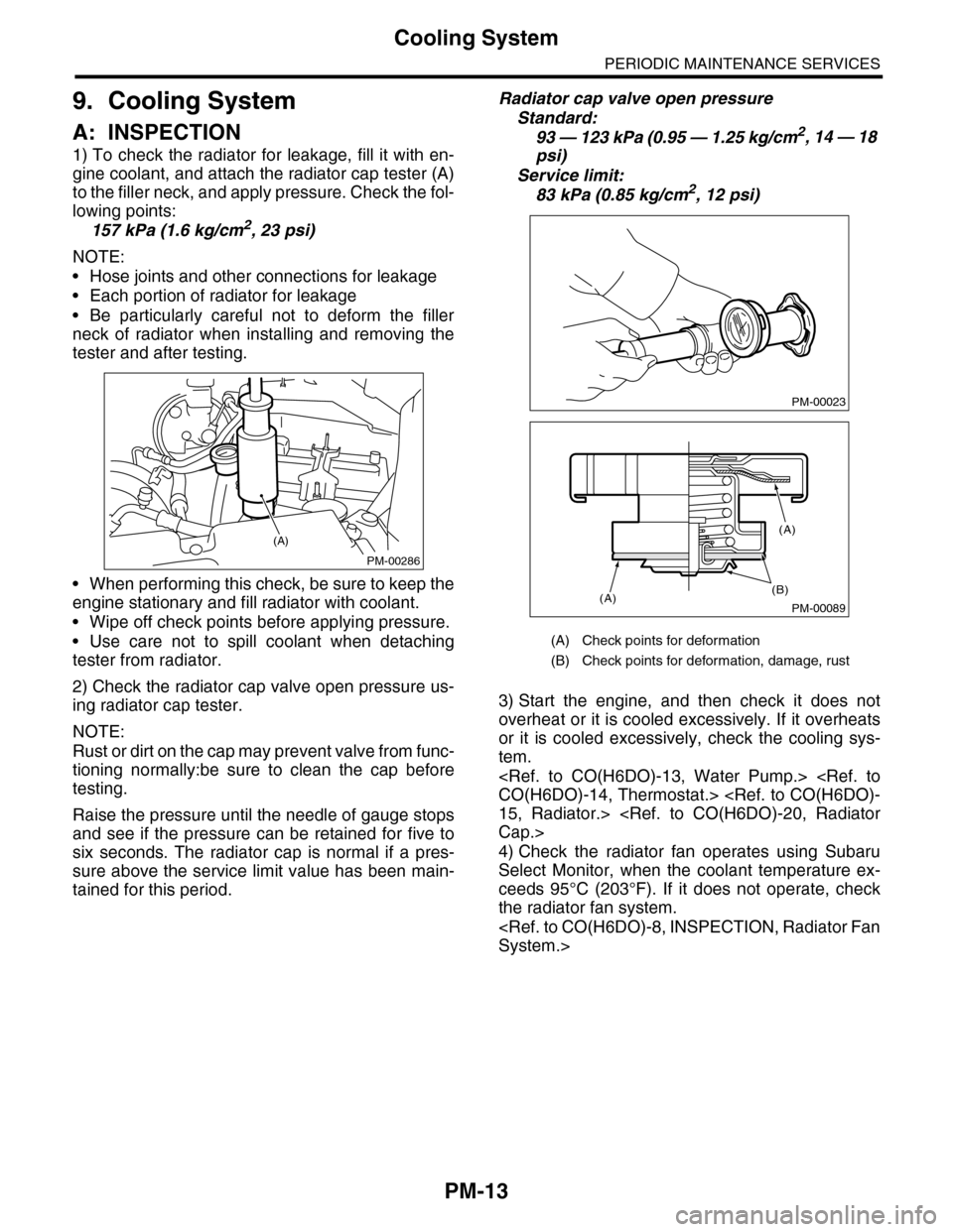
1) To check the radiator for leakage, fill it with en-
gine coolant, and attach the radiator cap tester (A)
to the filler neck, and apply pressure. Check the fol-
lowing points:
157 kPa (1.6 kg/cm2, 23 psi)
NOTE:
•Hose joints and other connections for leakage
•Each portion of radiator for leakage
•Be particularly careful not to deform the filler
neck of radiator when installing and removing the
tester and after testing.
•When performing this check, be sure to keep the
engine stationary and fill radiator with coolant.
•Wipe off check points before applying pressure.
•Use care not to spill coolant when detaching
tester from radiator.
2) Check the radiator cap valve open pressure us-
ing radiator cap tester.
NOTE:
Rust or dirt on the cap may prevent valve from func-
tioning normally:be sure to clean the cap before
testing.
Raise the pressure until the needle of gauge stops
and see if the pressure can be retained for five to
six seconds. The radiator cap is normal if a pres-
sure above the service limit value has been main-
tained for this period.
Radiator cap valve open pressure
Standard:
93 — 123 kPa (0.95 — 1.25 kg/cm2, 14 — 18
psi)
Service limit:
83 kPa (0.85 kg/cm2, 12 psi)
3) Start the engine, and then check it does not
overheat or it is cooled excessively. If it overheats
or it is cooled excessively, check the cooling sys-
tem.
4) Check the radiator fan operates using Subaru
Select Monitor, when the coolant temperature ex-
ceeds 95°C (203°F). If it does not operate, check
the radiator fan system.
PM-00286
(A)
(A) Check points for deformation
(B) Check points for deformation, damage, rust
PM-00023
PM-00089
(B)(A)
(A)
Page 1997 of 2453
PM-14
Engine Coolant
PERIODIC MAINTENANCE SERVICES
10.Engine Coolant
A: REPLACEMENT
1. REPLACEMENT OF ENGINE COOLANT
WARNING:
The radiator is of the pressurized type. Do not
attempt to open the radiator cap immediately
after the engine has been stopped.
1) Lift-up the vehicle.
2) Remove the under cover.
3) Place a container under drain pipe.
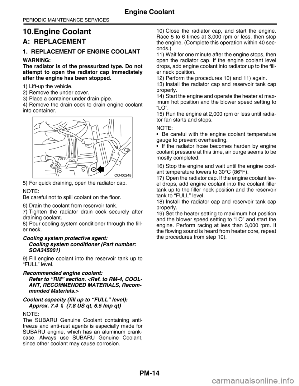
4) Remove the drain cock to drain engine coolant
into container.
5) For quick draining, open the radiator cap.
NOTE:
Be careful not to spill coolant on the floor.
6) Drain the coolant from reservoir tank.
7) Tighten the radiator drain cock securely after
draining coolant.
8) Pour cooling system conditioner through the fill-
er neck.
Cooling system protective agent:
Cooling system conditioner (Part number:
SOA345001)
9) Fill engine coolant into the reservoir tank up to
“FULL” level.
Recommended engine coolant:
Refer to “RM” section.
mended Materials.>
Coolant capacity (fill up to “FULL” level):
Approx. 7.4 2 (7.8 US qt, 6.5 Imp qt)
NOTE:
The SUBARU Genuine Coolant containing anti-
freeze and anti-rust agents is especially made for
SUBARU engine, which has an aluminum crank-
case. Always use SUBARU Genuine Coolant,
since other coolant may cause corrosion.
10) Close the radiator cap, and start the engine.
Race 5 to 6 times at 3,000 rpm or less, then stop
the engine. (Complete this operation within 40 sec-
onds.)
11) Wait for one minute after the engine stops, then
open the radiator cap. If the engine coolant level
drops, add engine coolant into radiator up to the fill-
er neck position.
12) Perform the procedures 10) and 11) again.
13) Install the radiator cap and reservoir tank cap
properly.
14) Start the engine and operate the heater at max-
imum hot position and the blower speed setting to
“LO”.
15) Run the engine at 2,000 rpm or less until radia-
tor fan starts and stops.
NOTE:
•Be careful with the engine coolant temperature
gauge to prevent overheating.
•If the radiator hose becomes harden by engine
coolant pressure at this time, air purge seems to be
mostly completed.
16) Stop the engine and wait until the engine cool-
ant temperature lowers to 30°C (86°F).
17) Open the radiator cap. If the engine coolant lev-
el drops, add engine coolant into the coolant filler
tank up to the filler neck position and the reservoir
tank to “FULL” level.
18) Install the radiator cap and reservoir tank cap
properly.
19) Set the heater setting to maximum hot position
and the blower speed setting to “LO” and start the
engine. Perform racing at less than 3,000 rpm. If
the flowing sound is heard from heater core, repeat
the procedures from step 10).
CO-00248
Page 1998 of 2453
PM-15
Engine Coolant
PERIODIC MAINTENANCE SERVICES
2. RELATIONSHIP OF SUBARU COOLANT
CONCENTRATION AND FREEZING TEM-
PERATURE
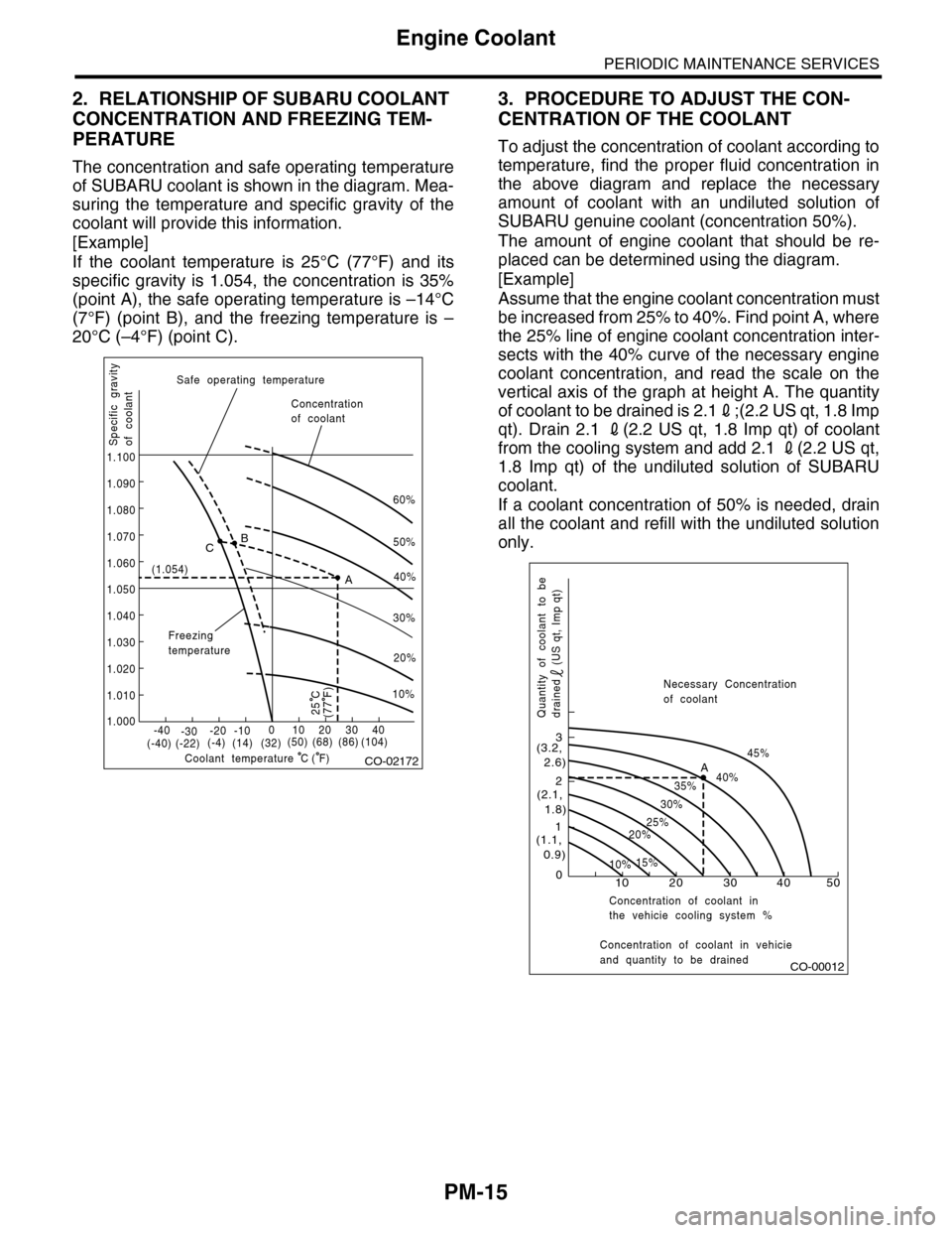
The concentration and safe operating temperature
of SUBARU coolant is shown in the diagram. Mea-
suring the temperature and specific gravity of the
coolant will provide this information.
[Example]
If the coolant temperature is 25°C (77°F) and its
specific gravity is 1.054, the concentration is 35%
(point A), the safe operating temperature is –14°C
(7°F) (point B), and the freezing temperature is –
20°C (–4°F) (point C).
3. PROCEDURE TO ADJUST THE CON-
CENTRATION OF THE COOLANT
To adjust the concentration of coolant according to
temperature, find the proper fluid concentration in
the above diagram and replace the necessary
amount of coolant with an undiluted solution of
SUBARU genuine coolant (concentration 50%).
The amount of engine coolant that should be re-
placed can be determined using the diagram.
[Example]
Assume that the engine coolant concentration must
be increased from 25% to 40%. Find point A, where
the 25% line of engine coolant concentration inter-
sects with the 40% curve of the necessary engine
coolant concentration, and read the scale on the
vertical axis of the graph at height A. The quantity
of coolant to be drained is 2.12;(2.2 US qt, 1.8 Imp
qt). Drain 2.1 2(2.2 US qt, 1.8 Imp qt) of coolant
from the cooling system and add 2.1 2(2.2 US qt,
1.8 Imp qt) of the undiluted solution of SUBARU
coolant.
If a coolant concentration of 50% is needed, drain
all the coolant and refill with the undiluted solution
only.
CO-02172
60%
(1.054)
1.000
1.010
1.020
1.030
1.040
1.050
1.060
1.070
1.080
1.090
1.100
Safe operating temperature
Freezingtemperature
Concentrationof coolant
Specific gravityof coolant
Coolant temperature
B
A
C
-40(-40) (-22)(-4)(14)(32)(50) (68) (86)
( F)
(104)-30-20 -10010203040
(77 F)
50%
40%
30%
20%
25 C
10%
C
CO-00012
100
1
2
3
(1.1, 0.9)
(2.1, 1.8)
(3.2, 2.6)
10%15%
25%20%
30%
35%40%
45%A
20 30 40 50
Concentration of coolant in vehicieand quantity to be drained
Quantity of coolant to bedrained (US qt, Imp qt)
Necessary Concentrationof coolant
Concentration of coolant inthe vehicie cooling system %
Page 2046 of 2453
5AT-30
Stall Test
AUTOMATIC TRANSMISSION
5. Stall Test
A: INSPECTION
NOTE:
The stall test is extremely important in diagnosing
the condition of an automatic transmission and en-
gine. It should be conducted to measure the engine
stall speeds in “R” and “2nd of manual mode”.
Purposes of the stall test:
•Operational check of the automatic transmission
clutch
•Operational check of the torque converter clutch
•Engine performance check
1) Check that the throttle valve fully opens.
2) Check that the engine oil level is correct.
3) Check that the coolant level is correct.
4) Check that the ATF level is correct.
5) Check that the differential gear oil level is cor-
rect.
6) Raise the ATF temperature to 70 to 80°C (158 to
176°F) by driving a distance of 5 to 10 km (3 to 6
miles). Confirm the ATF temperature on Subaru
Select Monitor.
tor.>
7) Place the wheel chocks at the front and rear of
all wheels and apply the parking brake.
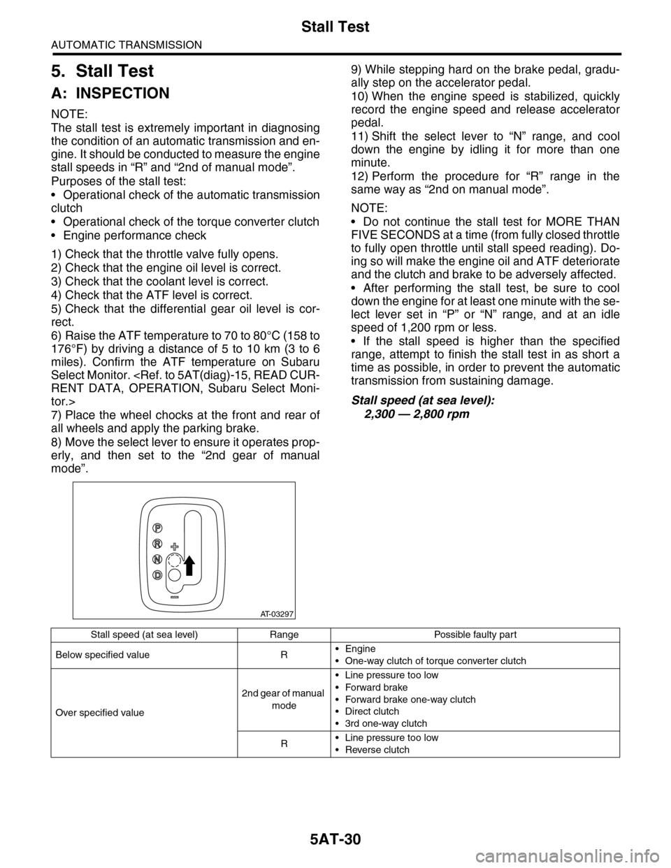
8) Move the select lever to ensure it operates prop-
erly, and then set to the “2nd gear of manual
mode”.
9) While stepping hard on the brake pedal, gradu-
ally step on the accelerator pedal.
10) When the engine speed is stabilized, quickly
record the engine speed and release accelerator
pedal.
11) Shift the select lever to “N” range, and cool
down the engine by idling it for more than one
minute.
12) Perform the procedure for “R” range in the
same way as “2nd on manual mode”.
NOTE:
•Do not continue the stall test for MORE THAN
FIVE SECONDS at a time (from fully closed throttle
to fully open throttle until stall speed reading). Do-
ing so will make the engine oil and ATF deteriorate
and the clutch and brake to be adversely affected.
•After performing the stall test, be sure to cool
down the engine for at least one minute with the se-
lect lever set in “P” or “N” range, and at an idle
speed of 1,200 rpm or less.
•If the stall speed is higher than the specified
range, attempt to finish the stall test in as short a
time as possible, in order to prevent the automatic
transmission from sustaining damage.
Stall speed (at sea level):
2,300 — 2,800 rpm
AT-03297
Stall speed (at sea level) Range Possible faulty part
Below specified value R•Engine
•One-way clutch of torque converter clutch
Over specified value
2nd gear of manual
mode
•Line pressure too low
•Forward brake
•Forward brake one-way clutch
•Direct clutch
•3rd one-way clutch
R•Line pressure too low
•Reverse clutch
Page 2317 of 2453
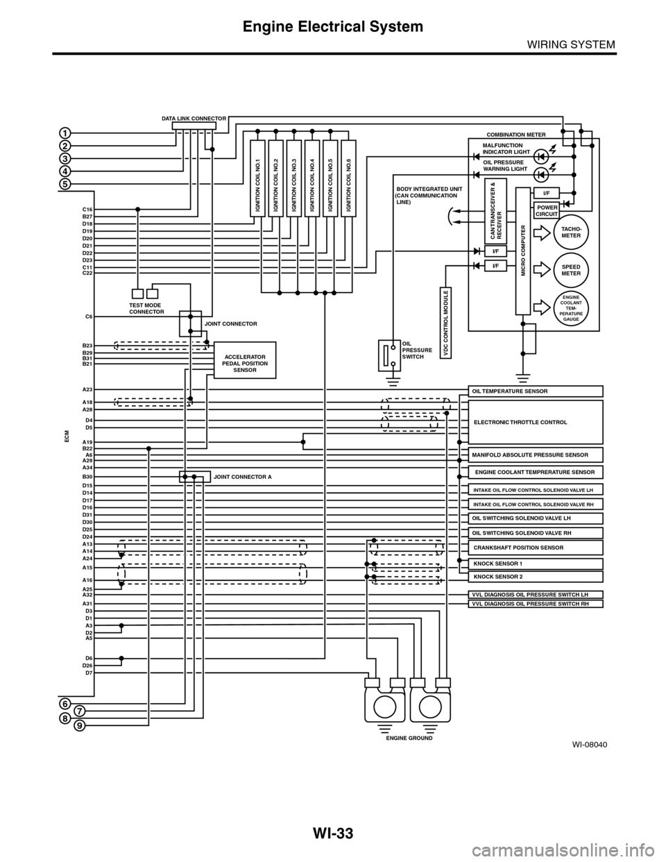
WI-33
Engine Electrical System
WIRING SYSTEM
WI-08040
A3D2
D22D23
POWERCIRCUIT
COMBINATION METER
C16B27D18D19D20D21
C11C22
C6
B23B29B31B21
1
2
3
4
5
6
ACCELERATORPEDAL POSITIONSENSOR
JOINT CONNECTOR A
JOINT CONNECTOR
MALFUNCTION INDICATOR LIGHTOIL PRESSUREWARNING LIGHT
I/F
I/F
I/F
VDC CONTROL MODULE
IGNITION COIL NO.1
BODY INTEGRATED UNIT(CAN COMMUNICATION LINE)
OILPRESSURESWITCH
CRANKSHAFT POSITION SENSORA13A14
ENGINE GROUND
ECM
A18A28
D4D5
A19B22A6A29A34
D15B30
D14D17D16D31D30
ELECTRONIC THROTTLE CONTROL
A24
A25A16
A15
A32
D1
MANIFOLD ABSOLUTE PRESSURE SENSOR
ENGINE COOLANT TEMPRERATURE SENSOR
VVL DIAGNOSIS OIL PRESSURE SWITCH RH
D25D24
KNOCK SENSOR 2
D6D26D7
A5
MICRO COMPUTER
CAN TRANSCEIVER &RECEIVER
OIL SWITCHING SOLENOID VALVE RH
TA C H O -METER
SPEEDMETER
ENGINECOOLANTTEM-PERATUREGAUGE
DATA LINK CONNECTOR
TEST MODECONNECTOR
OIL TEMPERATURE SENSORA23
A31D3
VVL DIAGNOSIS OIL PRESSURE SWITCH LH
KNOCK SENSOR 1
OIL SWITCHING SOLENOID VALVE LH
INTAKE OIL FLOW CONTROL SOLENOID VALVE RH
INTAKE OIL FLOW CONTROL SOLENOID VALVE LH
IGNITION COIL NO.2 IGNITION COIL NO.3 IGNITION COIL NO.4 IGNITION COIL NO.5 IGNITION COIL NO.6
789
Page 2320 of 2453
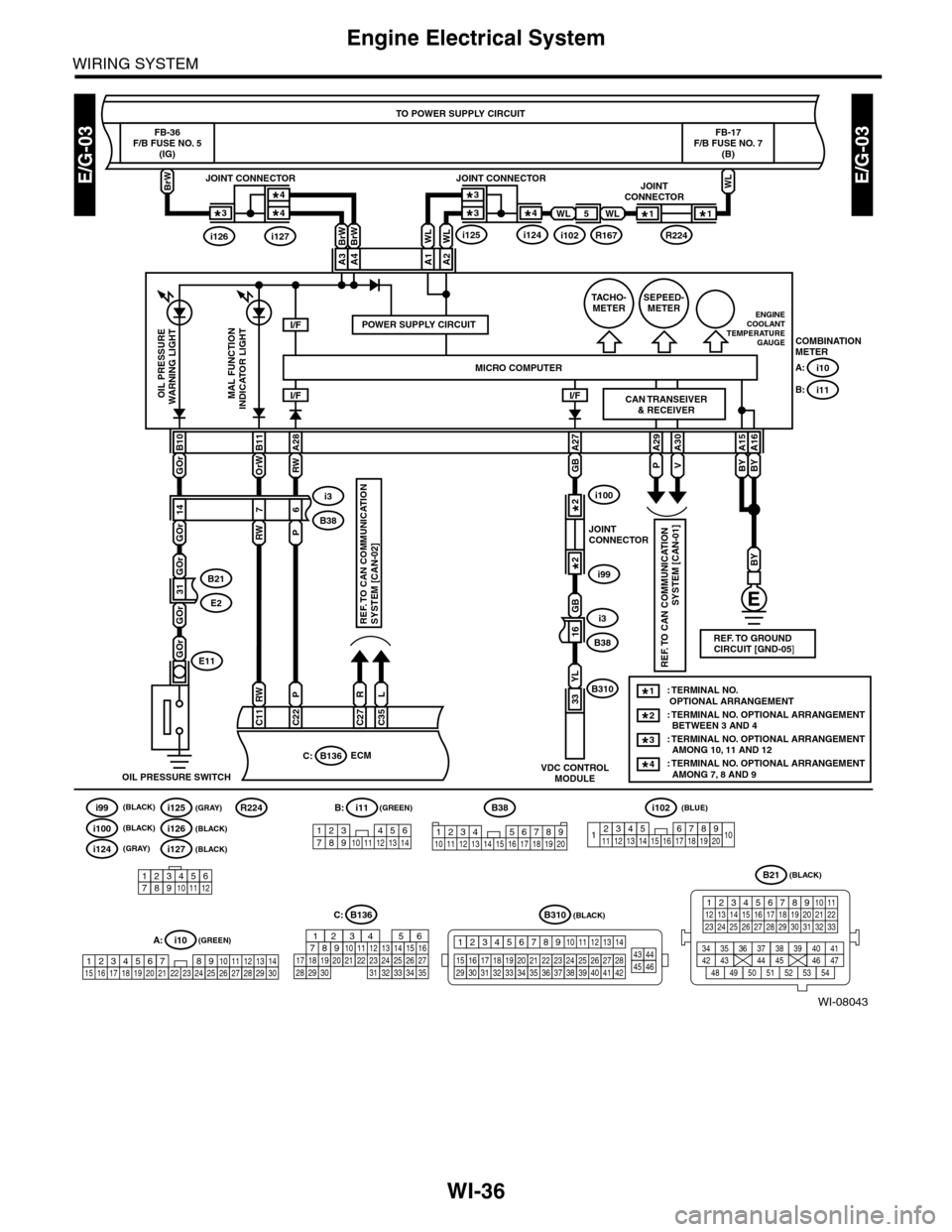
WI-36
Engine Electrical System
WIRING SYSTEM
WI-08043
E/G-03E/G-03
TO POWER SUPPLY CIRCUIT
FB-36F/B FUSE NO. 5(IG)
BrW
COMBINATIONMETER
i10A:
i11B:
BrWBrW
GOr
B10
OrW B11RW
A28
GB
GB A27
P
A29
V
A30
BY
A15
BY
A16
I/F
GOr
GOr
GOr
14
RWP
76
16
FB-17F/B FUSE NO. 7(B)
A2A1
B38
i3
B38
i3
POWER SUPPLY CIRCUITI/F
B21
E231
A3A4
ECM
OIL PRESSURE SWITCH
RW
C11
P
C22
R
C27
L
C35
C:B136
OIL PRESSUREWARNING LIGHTMAL FUNCTIONINDICATOR LIGHTI/F
MICRO COMPUTER
SEPEED-METERENGINECOOLANTTEMPERATUREGAUGE
TACHO-METER
B310YL
33
VDC CONTROLMODULE
BY
CAN TRANSEIVER& RECEIVER
E11GOr
B38
12345678910 11 12 13 14 15 16 17 18 19 20
B21
12345678910 1112 13 14 15 16 17 18 19 20 21 2223 24 25 26 27 28 29 30 31 32 33
34 3542 4336 3738 39
48 4950 5152 5354
40 41444546 47
REF. TO CAN COMMUNICATION
SYSTEM [CAN-01]
REF. TO CAN COMMUNICATION SYSTEM [CAN-02]
REF. TO GROUND CIRCUIT [GND-05]
JOINTCONNECTOR
i99
i1002*
2*
: TERMINAL NO. OPTIONAL ARRANGEMENT: TERMINAL NO. OPTIONAL ARRANGEMENT BETWEEN 3 AND 4
1*
2*
: TERMINAL NO. OPTIONAL ARRANGEMENT AMONG 10, 11 AND 123*
: TERMINAL NO. OPTIONAL ARRANGEMENT AMONG 7, 8 AND 94*
WL
WLWL
WLWL5
i102R167
JOINTCONNECTOR
R224
1*1*
JOINT CONNECTOR
i125i124
3*3*4*
JOINT CONNECTOR
i127i126
4*4*3*
1234567891413121110151617181920
i102(BLUE)(GREEN)
(GREEN)
(BLACK)
(BLACK)
i11
123 45678910 11 12 13 14
B:
i10
19 20 2115 16 17 182223242526272829301234568910 11 12 13 147
A:
C: B136
16101112131415252430
9871718192028212223293231
123456
2726333435
B310
1234
1516171819202122232425262728293031323334353637383940414245464344568910 11 12 13 147
123456789101112
i126(BLACK)
i124(GRAY)
i100(BLACK)
R224
i127(BLACK)
i99(BLACK)i125(GRAY)
Page 2326 of 2453
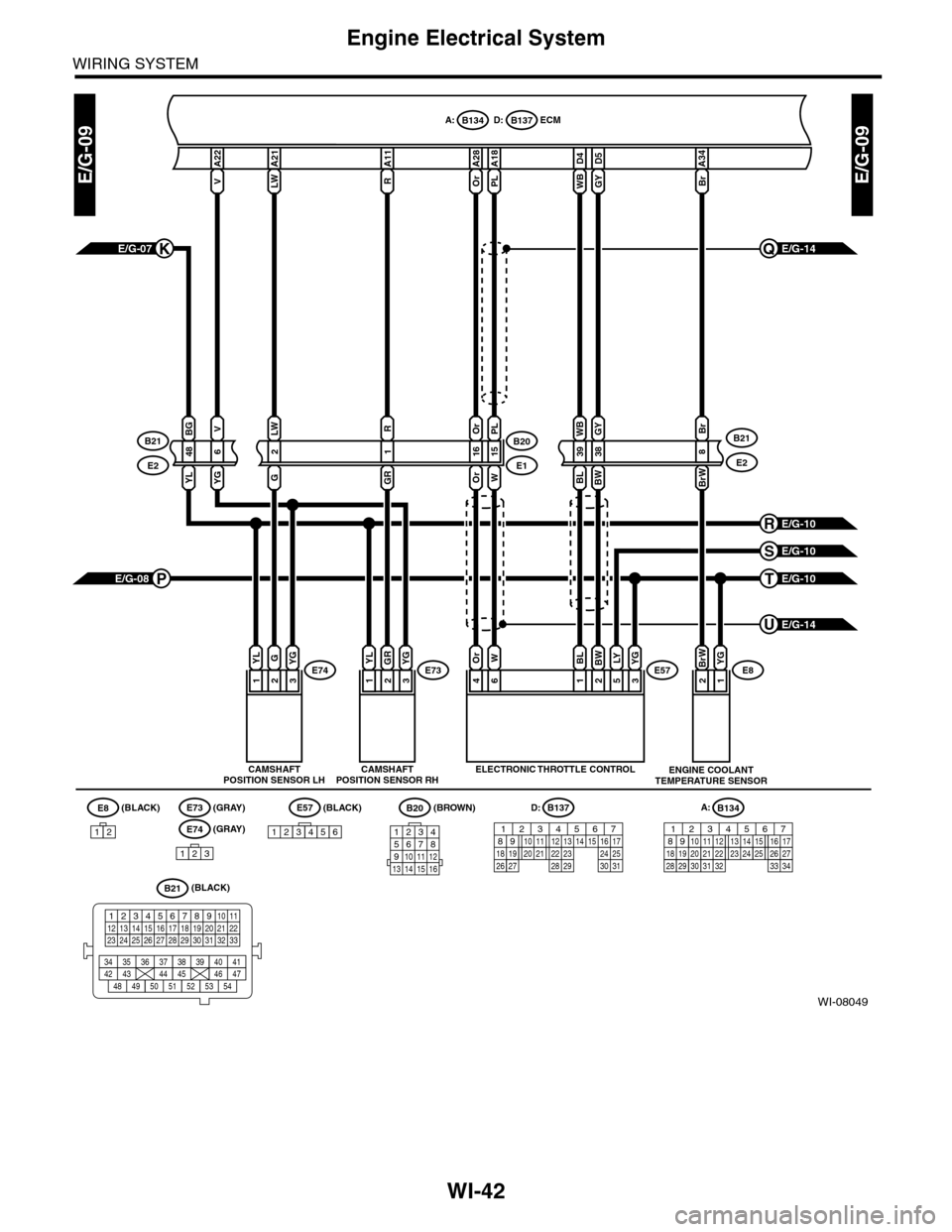
WI-42
Engine Electrical System
WIRING SYSTEM
WI-08049
E/G-09E/G-09
D:B137
A21
LW
A22
V
A28
Or
D5
GY
A18
PL
LWPL
13E73
B20
E1
43E57
215
Or
16
A11
R
R
1
YLGROr
6
W
1
BL
2
BW
5
LYE74
A:B134ECM
CAMSHAFTPOSITION SENSOR LHELECTRONIC THROTTLE CONTROL
(GRAY)(BLACK) (BROWN)
E/G-14Q
38398
GYWBBr
E2
B21
D4
WB
13
YLG
(BLACK)
(BLACK)
E8
12
E73E57
123456
B20
1234567891011 121413 15 16
B21
12345678910 1112 13 14 15 16 17 18 19 20 21 2223 24 25 26 27 28 29 30 31 32 33
34 3542 4336 3738 39
48 4950 5152 5354
40 41444546 47
Br
A34
E/G-07K
D: B137
85610 11 12 13 14 157213416
3019 20 2228 29
91718 2521 23 243126 27
E/G-10R
E/G-10S
WOrGRBWBLBrW
YG
2
YG
2
YG
E/G-14U
21E8BrW
ENGINE COOLANTTEMPERATURE SENSOR
YG
G
E/G-10TE/G-08P
E2
B21BG
486
YLYG
V
CAMSHAFTPOSITION SENSOR RH
E74
123
(GRAY)
A:B134
85610 11 12 13 14 157213416
3019 20 2228 29
91718252123 24323126 2733 34