Page 527 of 2453
LAN(diag)-71
Diagnostic Procedure with Diagnostic Trouble Code (DTC)
LAN SYSTEM (DIAGNOSTICS)
Step Check Yes No
1CHECK SUBARU SELECT MONITOR.
1) Display the current data of body integrated
unit using Subaru Select Monitor.
2) Display center monitor display fail.
Is OK displayed? Go to step 2.Refer to MFD or
navigation display.
REMOVAL, Navi-
gation Display.>
REMOVAL, Multi
Function Display
(MFD).>
2CHECK NAVIGATION.
1) Display the current data of body integrated
unit using Subaru Select Monitor.
2) Display NAVI fail.
Is OK displayed? Refer to MFD or
navigation display.
REMOVAL, Navi-
gation Display.>
REMOVAL, Multi
Function Display
(MFD).>
Refer to navigation
body.
23, REMOVAL,
Navigation Body.>
Page 528 of 2453

LAN(diag)-72
Diagnostic Procedure with Diagnostic Trouble Code (DTC)
LAN SYSTEM (DIAGNOSTICS)
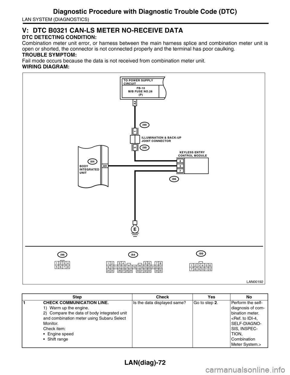
V: DTC B0321 CAN-LS METER NO-RECEIVE DATA
DTC DETECTING CONDITION:
Combination meter unit error, or harness between the main harness splice and combination meter unit is
open or shorted, the connector is not connected properly and the terminal has poor caulking.
TROUBLE SYMPTOM:
Fail mode occurs because the data is not received from combination meter unit.
WIRING DIAGRAM:
LAN00192
TO POWER SUPPLY CIRCUITFB-10M/B FUSE NO.28 (P)
1
4
3
7
A9
A4
5
BODY INTEGRATED UNIT
ILLUMINATION & BACK-UPJOINT CONNECTOR
KEYLESS ENTRY CONTROL MODULE
i84
i99
i99
i96
E
i84i96i99
123456789101112131415161718192021222324252627282930313233343510 11 12349561728
12345678
Step Check Yes No
1CHECK COMMUNICATION LINE.
1) Warm up the engine.
2) Compare the data of body integrated unit
and combination meter using Subaru Select
Monitor.
Check item:
•Engine speed
•Shift range
Is the data displayed same? Go to step 2.Perform the self-
diagnosis of com-
bination meter.
SELF-DIAGNO-
SIS, INSPEC-
TION,
Combination
Meter System.>
Page 530 of 2453

LAN(diag)-74
Diagnostic Procedure with Diagnostic Trouble Code (DTC)
LAN SYSTEM (DIAGNOSTICS)
W: DTC B0500 KEYLESS UART COM. MALFUNCTION
DTC DETECTING CONDITION:
UART between keyless control unit and body integrated unit is open or shorted, the connector is not con-
nected properly, or the terminal has poor caulking.
TROUBLE SYMPTOM:
Door lock does not operate with keyless.
WIRING DIAGRAM:
i128
1*
2*1*
2*
CAN JOINTCONNECTOR
i10
B283
A29A30
A27
A26
B26
B25
A: i84
B: B280B1
B14
TWISTED PAIR LINE
5467821931022 231112131415242526 2716171828 29192021 30
B280
i84
1234567891011121314151617181920212223242526272829303132333435
2345 678912 13 14 15 16 17 18 19 20 21 2210111
B283
i10
COMBINATIONMETER
BODYINTEGRATEDUNIT
AUTO A/CCONTROLMODULE
123456789101112
LAN00193
A:
B:
2*
1*
A6
A14
FRONTMONITOR
21
22MFD
2* :TERMINAL NO. OPTIONAL ARRANGEMENT AMONG 7, 8, 9, 10, 11 AND 12
1* :TERMINAL NO. OPTIONAL ARRANGEMENT AMONG 1, 2, 3, 4, 5 AND 6
i119
i122
A:
A:
A:
i119A:
i122
i128B:
MFDNAVI
MFD
NAVI
9
19 20
105672143131211
14 15 16 17
8
18222125262423
12345678910 11 12 13 14 15 16
345 678919 20 2114 15 16 17 1812101211 13 22
Step Check Yes No
1CHECK HARNESS.
1) Disconnect the body integrated unit con-
nector (i84) and keyless entry control unit con-
nector (i96).
2) Measure the resistance between har-
nesses.
Connector & terminal
(i84) No. 9 — (i96) No. 3:
Is the resistance less than 10
Ω?
Go to step 2.Repair the open
circuit of harness
or replace har-
ness.
Page 532 of 2453

LAN(diag)-76
General Diagnostic Table
LAN SYSTEM (DIAGNOSTICS)
13.General Diagnostic Table
A: INSPECTION
Read the DTC or inspect and diagnose the following data in the current data display using Subaru Select
Monitor.
1. LAN SYSTEM
Item OperationSpecificationsNoteYES NO
Diagnostic codeDTC is not displayed when inspect-
ing all DTCs.
DTC is not dis-
played.
Perfor m the diag-
nosis according to
DTC.
Refer to the DTC table
when there are trouble
codes of the CAN commu-
nication system for a mul-
tiple of modules.
LAN(diag)-31, FUNC-
TION CHECK, DTC
TA B L E , L i s t o f D i a g n o s t i c
Tr o u b l e C o d e ( D T C ) . >
Coolant Temp.
Check the current data display of
ECM, TCM and body integrated
unit. Three data value are the
same.
Same valuesInspect LAN sys-
tem.
If engine coolant tempera-
ture sensor is not OK,
inspect the sensor circuit.
R defogger SWIt turns to ON when pressing
switch. (Low-speed CAN is OK)Tu r n s t o O N .Inspect rear defog-
ger switch.
Rear defogger switch is
connected with Low-
speed CAN.
R defogger output When switch input, it is output. OutputReplace the body
integrated unit.
If not operating with out-
put, check the rear defog-
ger relay.
Door lock SWWhen locked with door lock switch,
it turns to ON.Tu r n s t o O N .Inspect door lock
switch.
Door lock actuatorWhen locked with door lock switch,
it is output.OutputReplace the body
integrated unit.—
Page 570 of 2453

OD(diag)-2
Basic Diagnostic Procedure
OCCUPANT DETECTION SYSTEM (DIAGNOSTICS)
1. Basic Diagnostic Procedure
A: PROCEDURE
Step Check Yes No
1CHECK WARNING LIGHT.
Check whether the airbag warning light in the
combination meter is lit.
Does the airbag warning light
illuminate?
Go to step 2.Perform the diag-
nosis according to
phenomenon of
the problem.
2READ DTC.
1) Turn the ignition switch to OFF.
2) Connect the Subaru Select Monitor to data
link connector.
3) Turn the ignition switch to ON, and the Sub-
aru Select Monitor power switch to ON.
4) Read the DTC.
OPERATION, Read Diagnostic Trouble Code
(DTC).>
NOTE:If the communication function of the Subaru Se-
lect Monitor cannot be executed normally,
check the communication circuit.
OD(diag)-19, COMMUNICATION FOR INI-
TIALIZING IMPOSSIBLE, INSPECTION, Sub-
aru Select Monitor.>
5) Record all DTCs and freeze frame data.
Is DTC displayed? Go to step 3.Go to “Airbag
Wa r ni n g L ig h t Fa i l-
ure”.
AB(diag)-40, Air-
bag Warning Light
Fai lu r e.>
3PERFORM DIAGNOSIS.
1) Determine the possible cause from “List of
Diagnostic Trouble Code.”
25, List of Diagnostic Trouble Code (DTC).>
2) Inspect the DTC using “List of Diagnostic
Tr o u b l e C o d e ( D T C ) ” .
3) Repair the trouble cause.
4) Perform the clear memory mode.
OD(diag)-22, Clear Memory Mode.>
5) Perform the inspection mode.
OD(diag)-21, Inspection Mode.>
6) Read any other DTCs displayed.
Is DTC displayed? Perform the proce-
dure 1) to 5) in
step 3.
Finish the diagno-
sis.
Page 572 of 2453

OD(diag)-4
General Description
OCCUPANT DETECTION SYSTEM (DIAGNOSTICS)
3. General Description
A: CAUTION
1) Never remove the occupant detection control
module, occupant detection sensor and seat cush-
ion from seat frame because the occupant detec-
tion system is integrated into seat frame as one
unit.
2) Always perform “system calibration (Rezeroing)”
when removing or removing and disassembling the
passenger’s seat.
CALIBRATION (REZEROING), OPERATION,
Subaru Select Monitor.>
3) Never connect the battery in reverse polarity.
•Occupant detection system may be destroyed in-
stantly.
4) Do not disconnect the battery terminals while the
engine is running.
•A large counter electromotive force will be gener-
ated in the generator, and this voltage may damage
electronic parts such as occupant detection control
module.
5) Before disconnecting the connectors of each
sensor and control module, be sure to turn the igni-
tion switch to OFF and wait for 20 seconds or more.
•Occupant detection control module may be dam-
aged.
6) Every A/C-related part is a precision part. Do not
drop them.
7) Airbag system wiring harness is routed near the
A/C control panel and junction box.
CAUTION:
•For airbag system, yellow-colored wiring har-
ness and connectors are all used. Do not use
the electrical test equipment on these circuits.
•Be careful not to damage the airbag system
wiring harness when servicing the occupant
detection system.
•Refer to “Airbag System” when repairing the
occupant detection system.
4, CAUTION, General Description.>
B: INSPECTION
Measure the battery voltage and check electrolyte.
Standard voltage: 12 V
Specific gravity: Above 1.260
Page 573 of 2453
OD(diag)-5
General Description
OCCUPANT DETECTION SYSTEM (DIAGNOSTICS)
C: PREPARATION TOOL
CAUTION:
To measure the voltage and resistance of airbag system and occupant detection system compo-
nents, be sure to use the specified test harness.
1. SPECIAL TOOL
ILLUSTRATION TOOL NUMBER DESCRIPTION REMARKS
24082AA010 CARTRIDGE Troubleshooting for electrical system.
22771AA030 SUBARU SELECT
MONITOR KIT
Tr o u b l e s h o o t i n g f o r e l e c t r i c a l s y s t e m .
ST24082AA260
ST22771AA030
Page 585 of 2453

OD(diag)-17
Subaru Select Monitor
OCCUPANT DETECTION SYSTEM (DIAGNOSTICS)
7. Subaru Select Monitor
A: OPERATION
1. READ DIAGNOSTIC TROUBLE CODE (DTC)
When malfunction of the airbag system and the occupant detection system occur, the DTC stored in airbag
control module will be read out.
Refer to the DTC readout of the airbag system (diagnosis).
lect Monitor.>
NOTE:
•For details concerning operation procedure, refer to the “SUBARU SELECT MONITOR OPERATION
MANUAL”.
•For details concerning DTCs, refer to the “List of Diagnostic Trouble Code (Airbag system, Occupant de-
tection system).”
ble Code (DTC).>
2. DISPLAY OF STATUS INFORMATION
Check the operating condition of each sensor in the event of malfunction in seat belt buckle switch and seat
position sensor, or when the seat belt buckle switch and seat position sensor has been replaced.
1) On the «Main Menu» display screen, select the {Each System Check} and press the [YES] key.
2) On the «System Selection Menu» display screen, select the {Airbag System} and press the [YES] key.
3) On the «Airbag System» display screen, select the {Status Data} and press the [YES] key.
The following table is for support data.
*1: The seat position is forward.
*2: The seat position is rearward.
*3: Displayed when data other than before and behind the seat, such as the breakdown etc, is input.
*4: Displayed when it is initial.
*5: Seat position sensor not supported
*6. Seat belt fastened
*7. Seat belt not fastened
*8: Displayed when data other than belt fastened or not fastened, such as breakdowns is input.
*9: Seat belt buckle switch not supported
*10: Passenger's seat air bag operating state
*11: Passenger's seat air bag non-operating state
NOTE:
For details concerning operation procedure, refer to the “SUBARU SELECT MONITOR OPERATION MAN-
UAL”.
Item Display Contents
Seat position sensor LHFr o nt p os it i on *1/Rear position *2 /Other *3/Initial Setting *3 /–– *5
Seat position sensor RH–– *5
Seat belt buckle switch LHBuckled *6/Unbuckled *7 /Other *8/Initial Setting *4 /–– *9
Seat belt buckle switch RHBuckled *6/Unbuckled *7 /Other *8/Initial Setting *4 /–– *9
Passenger’s airbag control statusON *10/OFF *11 /Initial Setting *4