2009 SUBARU TRIBECA engine
[x] Cancel search: enginePage 2235 of 2453
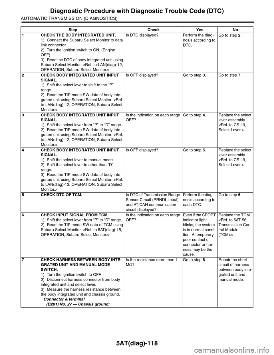
5AT(diag)-118
Diagnostic Procedure with Diagnostic Trouble Code (DTC)
AUTOMATIC TRANSMISSION (DIAGNOSTICS)
Step Check Yes No
1CHECK THE BODY INTEGRATED UNIT.
1) Connect the Subaru Select Monitor to data
link connector.
2) Turn the ignition switch to ON. (Engine
OFF)
3) Read the DTC of body integrated unit using
Subaru Select Monitor.
Is DTC displayed? Perform the diag-
nosis according to
DTC.
Go to step 2.
2CHECK BODY INTEGRATED UNIT INPUT
SIGNAL.
1) Shift the select lever to shift to the “P”
range.
2) Read the TIP mode SW data of body inte-
grated unit using Subaru Select Monitor.
Monitor.>
Is OFF displayed? Go to step 3.Go to step 7.
3CHECK BODY INTEGRATED UNIT INPUT
SIGNAL.
1) Shift the select lever from “P” to “D” range.
2) Read the TIP mode SW data of body inte-
grated unit using Subaru Select Monitor.
Monitor.>
Is the indication on each range
OFF?
Go to step 4.Replace the select
lever assembly.
4CHECK BODY INTEGRATED UNIT INPUT
SIGNAL.
1) Shift the select lever to manual mode.
2) Shift the select lever to other than “D”
range.
3) Read the TIP mode SW data of body inte-
grated unit using Subaru Select Monitor.
Monitor.>
Is OFF displayed? Go to step 5.Replace the select
lever assembly.
5CHECK DTC OF TCM.Is DTC of Transmission Range
Sensor Circuit (PRNDL Input)
and AT CAN communication
circuit displayed?
Pe r for m t h e d ia g -
nosis according to
each DTC.
Go to step 6.
6CHECK INPUT SIGNAL FROM TCM.
1) Shift the select lever from “P” to “D” range.
2) Read the TIP mode SW data of TCM using
Subaru Select Monitor.
Is the indication on each range
OFF?
Even if the SPORT
indicator light
blinks, the system
is in normal condi-
tion. A temporary
poor contact of
connector or har-
ness may be the
cause.
Replace the TCM.
trol Module
(TCM).>
7CHECK HARNESS BETWEEN BODY INTE-
GRATED UNIT AND MANUAL MODE
SWITCH.
1) Turn the ignition switch to OFF.
2) Disconnect harness connector from body
integrated unit and select lever.
3) Measure the harness resistance between
the body integrated unit and chassis ground.
Connector & terminal
(B281) No. 27 — Chassis ground:
Is the resistance more than 1
MΩ?
Go to step 8.Repair the short
circuit of harness
between body inte-
grated unit and
manual mode.
Page 2239 of 2453
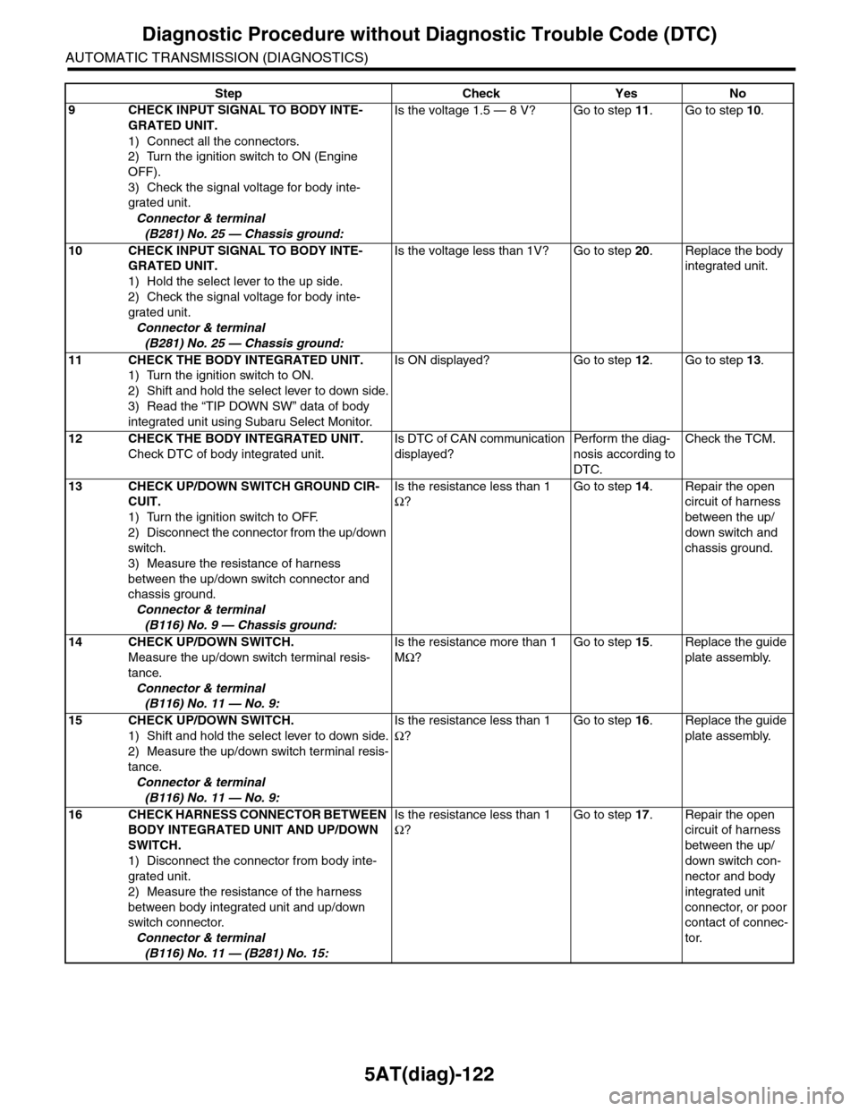
5AT(diag)-122
Diagnostic Procedure without Diagnostic Trouble Code (DTC)
AUTOMATIC TRANSMISSION (DIAGNOSTICS)
9CHECK INPUT SIGNAL TO BODY INTE-
GRATED UNIT.
1) Connect all the connectors.
2) Turn the ignition switch to ON (Engine
OFF).
3) Check the signal voltage for body inte-
grated unit.
Connector & terminal
(B281) No. 25 — Chassis ground:
Is the voltage 1.5 — 8 V? Go to step 11.Go to step 10.
10 CHECK INPUT SIGNAL TO BODY INTE-
GRATED UNIT.
1) Hold the select lever to the up side.
2) Check the signal voltage for body inte-
grated unit.
Connector & terminal
(B281) No. 25 — Chassis ground:
Is the voltage less than 1V? Go to step 20.Replace the body
integrated unit.
11 CHECK THE BODY INTEGRATED UNIT.
1) Turn the ignition switch to ON.
2) Shift and hold the select lever to down side.
3) Read the “TIP DOWN SW” data of body
integrated unit using Subaru Select Monitor.
Is ON displayed? Go to step 12.Go to step 13.
12 CHECK THE BODY INTEGRATED UNIT.
Check DTC of body integrated unit.
Is DTC of CAN communication
displayed?
Pe r for m t h e d ia g -
nosis according to
DTC.
Check the TCM.
13 CHECK UP/DOWN SWITCH GROUND CIR-
CUIT.
1) Turn the ignition switch to OFF.
2) Disconnect the connector from the up/down
switch.
3) Measure the resistance of harness
between the up/down switch connector and
chassis ground.
Connector & terminal
(B116) No. 9 — Chassis ground:
Is the resistance less than 1
Ω?
Go to step 14.Repair the open
circuit of harness
between the up/
down switch and
chassis ground.
14 CHECK UP/DOWN SWITCH.
Measure the up/down switch terminal resis-
tance.
Connector & terminal
(B116) No. 11 — No. 9:
Is the resistance more than 1
MΩ?
Go to step 15.Replace the guide
plate assembly.
15 CHECK UP/DOWN SWITCH.
1) Shift and hold the select lever to down side.
2) Measure the up/down switch terminal resis-
tance.
Connector & terminal
(B116) No. 11 — No. 9:
Is the resistance less than 1
Ω?
Go to step 16.Replace the guide
plate assembly.
16 CHECK HARNESS CONNECTOR BETWEEN
BODY INTEGRATED UNIT AND UP/DOWN
SWITCH.
1) Disconnect the connector from body inte-
grated unit.
2) Measure the resistance of the harness
between body integrated unit and up/down
switch connector.
Connector & terminal
(B116) No. 11 — (B281) No. 15:
Is the resistance less than 1
Ω?
Go to step 17.Repair the open
circuit of harness
between the up/
down switch con-
nector and body
integrated unit
connector, or poor
contact of connec-
tor.
Step Check Yes No
Page 2240 of 2453
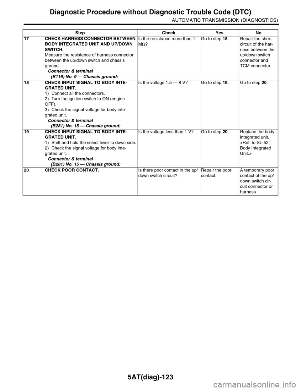
5AT(diag)-123
Diagnostic Procedure without Diagnostic Trouble Code (DTC)
AUTOMATIC TRANSMISSION (DIAGNOSTICS)
17 CHECK HARNESS CONNECTOR BETWEEN
BODY INTEGRATED UNIT AND UP/DOWN
SWITCH.
Measure the resistance of harness connector
between the up/down switch and chassis
ground.
Connector & terminal
(B116) No. 9 — Chassis ground:
Is the resistance more than 1
MΩ?
Go to step 18.Repair the short
circuit of the har-
ness between the
up/down switch
connector and
TCM connector.
18 CHECK INPUT SIGNAL TO BODY INTE-
GRATED UNIT.
1) Connect all the connectors.
2) Turn the ignition switch to ON (engine
OFF).
3) Check the signal voltage for body inte-
grated unit.
Connector & terminal
(B281) No. 15 — Chassis ground:
Is the voltage 1.5 — 8 V? Go to step 19.Go to step 20.
19 CHECK INPUT SIGNAL TO BODY INTE-
GRATED UNIT.
1) Shift and hold the select lever to down side.
2) Check the signal voltage for body inte-
grated unit.
Connector & terminal
(B281) No. 15 — Chassis ground:
Is the voltage less than 1 V? Go to step 20.Replace the body
integrated unit.
Unit.>
20 CHECK POOR CONTACT.Is there poor contact in the up/
down switch circuit?
Repair the poor
contact.
A temporary poor
contact of the up/
down switch cir-
cuit connector or
harness
Step Check Yes No
Page 2242 of 2453
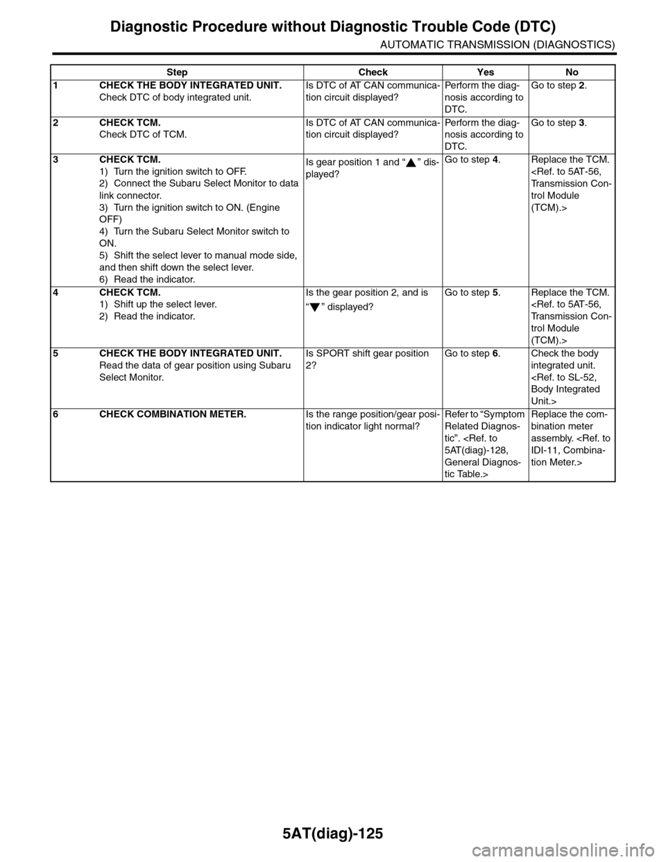
5AT(diag)-125
Diagnostic Procedure without Diagnostic Trouble Code (DTC)
AUTOMATIC TRANSMISSION (DIAGNOSTICS)
Step Check Yes No
1CHECK THE BODY INTEGRATED UNIT.
Check DTC of body integrated unit.
Is DTC of AT CAN communica-
tion circuit displayed?
Pe r for m t h e d ia g -
nosis according to
DTC.
Go to step 2.
2CHECK TCM.
Check DTC of TCM.
Is DTC of AT CAN communica-
tion circuit displayed?
Pe r for m t h e d ia g -
nosis according to
DTC.
Go to step 3.
3CHECK TCM.
1) Turn the ignition switch to OFF.
2) Connect the Subaru Select Monitor to data
link connector.
3) Turn the ignition switch to ON. (Engine
OFF)
4) Turn the Subaru Select Monitor switch to
ON.
5) Shift the select lever to manual mode side,
and then shift down the select lever.
6) Read the indicator.
Is gear position 1 and “ ” dis-
played?
Go to step 4.Replace the TCM.
trol Module
(TCM).>
4CHECK TCM.
1) Shift up the select lever.
2) Read the indicator.
Is the gear position 2, and is
“” displayed?
Go to step 5.Replace the TCM.
trol Module
(TCM).>
5CHECK THE BODY INTEGRATED UNIT.
Read the data of gear position using Subaru
Select Monitor.
Is SPORT shift gear position
2?
Go to step 6.Check the body
integrated unit.
Unit.>
6CHECK COMBINATION METER.Is the range position/gear posi-
tion indicator light normal?
Refer to “Symptom
Related Diagnos-
tic”.
General Diagnos-
tic Table.>
Replace the com-
bination meter
assembly.
tion Meter.>
Page 2244 of 2453
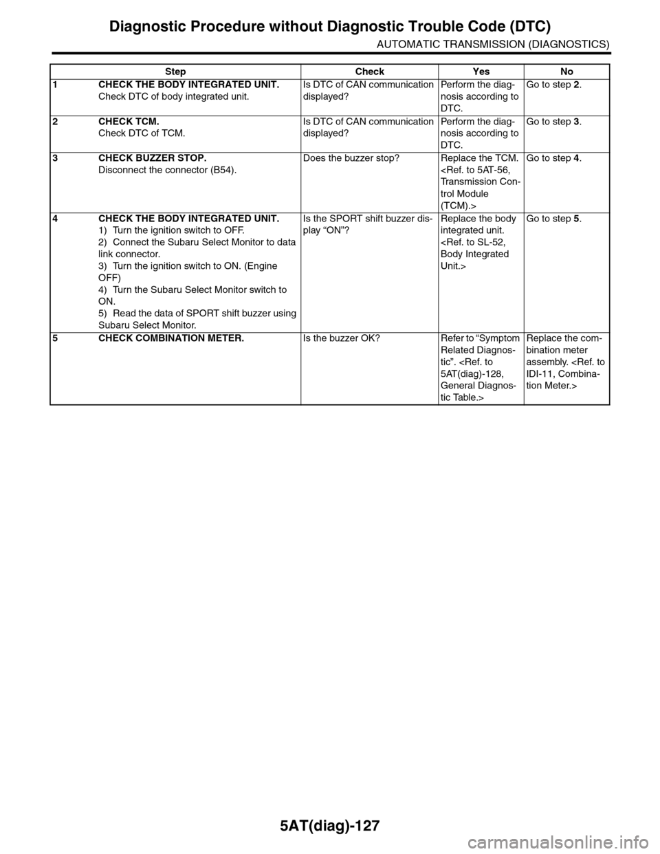
5AT(diag)-127
Diagnostic Procedure without Diagnostic Trouble Code (DTC)
AUTOMATIC TRANSMISSION (DIAGNOSTICS)
Step Check Yes No
1CHECK THE BODY INTEGRATED UNIT.
Check DTC of body integrated unit.
Is DTC of CAN communication
displayed?
Pe r for m t h e d ia g -
nosis according to
DTC.
Go to step 2.
2CHECK TCM.
Check DTC of TCM.
Is DTC of CAN communication
displayed?
Pe r for m t h e d ia g -
nosis according to
DTC.
Go to step 3.
3CHECK BUZZER STOP.
Disconnect the connector (B54).
Does the buzzer stop? Replace the TCM.
trol Module
(TCM).>
Go to step 4.
4CHECK THE BODY INTEGRATED UNIT.
1) Turn the ignition switch to OFF.
2) Connect the Subaru Select Monitor to data
link connector.
3) Turn the ignition switch to ON. (Engine
OFF)
4) Turn the Subaru Select Monitor switch to
ON.
5) Read the data of SPORT shift buzzer using
Subaru Select Monitor.
Is the SPORT shift buzzer dis-
play “ON”?
Replace the body
integrated unit.
Unit.>
Go to step 5.
5CHECK COMBINATION METER.Is the buzzer OK? Refer to “Symptom
Related Diagnos-
tic”.
General Diagnos-
tic Table.>
Replace the com-
bination meter
assembly.
tion Meter.>
Page 2245 of 2453
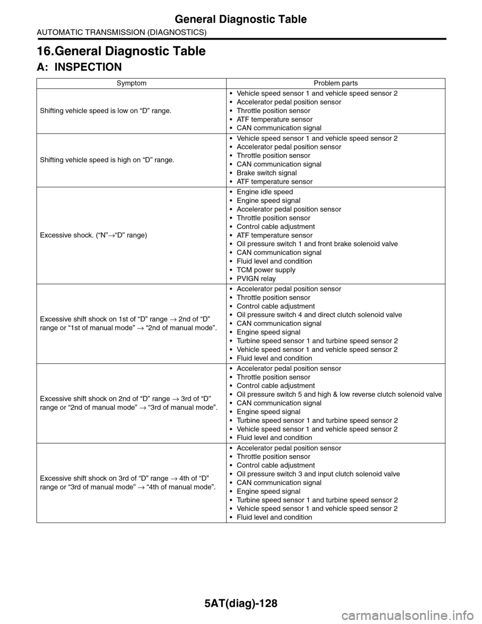
5AT(diag)-128
General Diagnostic Table
AUTOMATIC TRANSMISSION (DIAGNOSTICS)
16.General Diagnostic Table
A: INSPECTION
Symptom Problem parts
Shifting vehicle speed is low on “D” range.
•Vehicle speed sensor 1 and vehicle speed sensor 2
•Accelerator pedal position sensor
•Throttle position sensor
•ATF temperature sensor
•CAN communication signal
Shifting vehicle speed is high on “D” range.
•Vehicle speed sensor 1 and vehicle speed sensor 2
•Accelerator pedal position sensor
•Throttle position sensor
•CAN communication signal
•Brake switch signal
•ATF temperature sensor
Excessive shock. (“N”→“D” range)
•Engine idle speed
•Engine speed signal
•Accelerator pedal position sensor
•Throttle position sensor
•Control cable adjustment
•ATF temperature sensor
•Oil pressure switch 1 and front brake solenoid valve
•CAN communication signal
•Fluid level and condition
•TCM power supply
•PVIGN relay
Excessive shift shock on 1st of “D” range → 2nd of “D”
range or “1st of manual mode” → “2nd of manual mode”.
•Accelerator pedal position sensor
•Throttle position sensor
•Control cable adjustment
•Oil pressure switch 4 and direct clutch solenoid valve
•CAN communication signal
•Engine speed signal
•Turbine speed sensor 1 and turbine speed sensor 2
•Vehicle speed sensor 1 and vehicle speed sensor 2
•Fluid level and condition
Excessive shift shock on 2nd of “D” range → 3rd of “D”
range or “2nd of manual mode” → “3rd of manual mode”.
•Accelerator pedal position sensor
•Throttle position sensor
•Control cable adjustment
•Oil pressure switch 5 and high & low reverse clutch solenoid valve
•CAN communication signal
•Engine speed signal
•Turbine speed sensor 1 and turbine speed sensor 2
•Vehicle speed sensor 1 and vehicle speed sensor 2
•Fluid level and condition
Excessive shift shock on 3rd of “D” range → 4th of “D”
range or “3rd of manual mode” → “4th of manual mode”.
•Accelerator pedal position sensor
•Throttle position sensor
•Control cable adjustment
•Oil pressure switch 3 and input clutch solenoid valve
•CAN communication signal
•Engine speed signal
•Turbine speed sensor 1 and turbine speed sensor 2
•Vehicle speed sensor 1 and vehicle speed sensor 2
•Fluid level and condition
Page 2246 of 2453
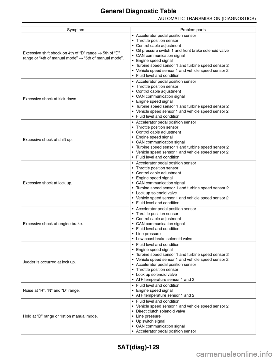
5AT(diag)-129
General Diagnostic Table
AUTOMATIC TRANSMISSION (DIAGNOSTICS)
Excessive shift shock on 4th of “D” range → 5th of “D”
range or “4th of manual mode” → “5th of manual mode”.
•Accelerator pedal position sensor
•Throttle position sensor
•Control cable adjustment
•Oil pressure switch 1 and front brake solenoid valve
•CAN communication signal
•Engine speed signal
•Turbine speed sensor 1 and turbine speed sensor 2
•Vehicle speed sensor 1 and vehicle speed sensor 2
•Fluid level and condition
Excessive shock at kick down.
•Accelerator pedal position sensor
•Throttle position sensor
•Control cable adjustment
•CAN communication signal
•Engine speed signal
•Turbine speed sensor 1 and turbine speed sensor 2
•Vehicle speed sensor 1 and vehicle speed sensor 2
•Fluid level and condition
Excessive shock at shift up.
•Accelerator pedal position sensor
•Throttle position sensor
•Control cable adjustment
•Engine speed signal
•CAN communication signal
•Turbine speed sensor 1 and turbine speed sensor 2
•Vehicle speed sensor 1 and vehicle speed sensor 2
•Fluid level and condition
Excessive shock at lock up.
•Accelerator pedal position sensor
•Throttle position sensor
•Control cable adjustment
•Engine speed signal
•CAN communication signal
•Turbine speed sensor 1 and turbine speed sensor 2
•Lock up solenoid valve
•Vehicle speed sensor 1 and vehicle speed sensor 2
•Fluid level and condition
Excessive shock at engine brake.
•Accelerator pedal position sensor
•Throttle position sensor
•Control cable adjustment
•CAN communication signal
•Fluid level and condition
•Line pressure
•Low coast brake solenoid valve
Judder is occurred at lock up.
•Fluid level and condition
•Engine speed signal
•Turbine speed sensor 1 and turbine speed sensor 2
•Vehicle speed sensor 1 and vehicle speed sensor 2
•Accelerator pedal position sensor
•Throttle position sensor
•Lock up solenoid valve
•ATF temperature sensor 1 and 2
Noise at “R”, “N” and “D” range.
•Fluid level and condition
•Engine speed signal
•ATF temperature sensor 1 and 2
Hold at “D” range or 1st on manual mode.
•Fluid level and condition
•Vehicle speed sensor 1 and vehicle speed sensor 2
•Direct clutch solenoid valve
•Line pressure
•Up switch signal
•CAN communication signal
•Accelerator pedal position sensor
Symptom Problem parts
Page 2248 of 2453
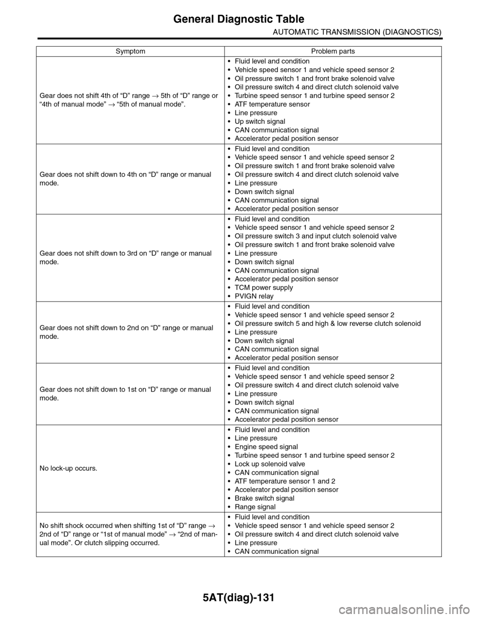
5AT(diag)-131
General Diagnostic Table
AUTOMATIC TRANSMISSION (DIAGNOSTICS)
Gear does not shift 4th of “D” range → 5th of “D” range or
“4th of manual mode” → “5th of manual mode”.
•Fluid level and condition
•Vehicle speed sensor 1 and vehicle speed sensor 2
•Oil pressure switch 1 and front brake solenoid valve
•Oil pressure switch 4 and direct clutch solenoid valve
•Turbine speed sensor 1 and turbine speed sensor 2
•ATF temperature sensor
•Line pressure
•Up switch signal
•CAN communication signal
•Accelerator pedal position sensor
Gear does not shift down to 4th on “D” range or manual
mode.
•Fluid level and condition
•Vehicle speed sensor 1 and vehicle speed sensor 2
•Oil pressure switch 1 and front brake solenoid valve
•Oil pressure switch 4 and direct clutch solenoid valve
•Line pressure
•Down switch signal
•CAN communication signal
•Accelerator pedal position sensor
Gear does not shift down to 3rd on “D” range or manual
mode.
•Fluid level and condition
•Vehicle speed sensor 1 and vehicle speed sensor 2
•Oil pressure switch 3 and input clutch solenoid valve
•Oil pressure switch 1 and front brake solenoid valve
•Line pressure
•Down switch signal
•CAN communication signal
•Accelerator pedal position sensor
•TCM power supply
•PVIGN relay
Gear does not shift down to 2nd on “D” range or manual
mode.
•Fluid level and condition
•Vehicle speed sensor 1 and vehicle speed sensor 2
•Oil pressure switch 5 and high & low reverse clutch solenoid
•Line pressure
•Down switch signal
•CAN communication signal
•Accelerator pedal position sensor
Gear does not shift down to 1st on “D” range or manual
mode.
•Fluid level and condition
•Vehicle speed sensor 1 and vehicle speed sensor 2
•Oil pressure switch 4 and direct clutch solenoid valve
•Line pressure
•Down switch signal
•CAN communication signal
•Accelerator pedal position sensor
No lock-up occurs.
•Fluid level and condition
•Line pressure
•Engine speed signal
•Turbine speed sensor 1 and turbine speed sensor 2
•Lock up solenoid valve
•CAN communication signal
•ATF temperature sensor 1 and 2
•Accelerator pedal position sensor
•Brake switch signal
•Range signal
No shift shock occurred when shifting 1st of “D” range →
2nd of “D” range or “1st of manual mode” → “2nd of man-
ual mode”. Or clutch slipping occurred.
•Fluid level and condition
•Vehicle speed sensor 1 and vehicle speed sensor 2
•Oil pressure switch 4 and direct clutch solenoid valve
•Line pressure
•CAN communication signal
Symptom Problem parts