2009 SUBARU TRIBECA engine
[x] Cancel search: enginePage 2249 of 2453
5AT(diag)-132
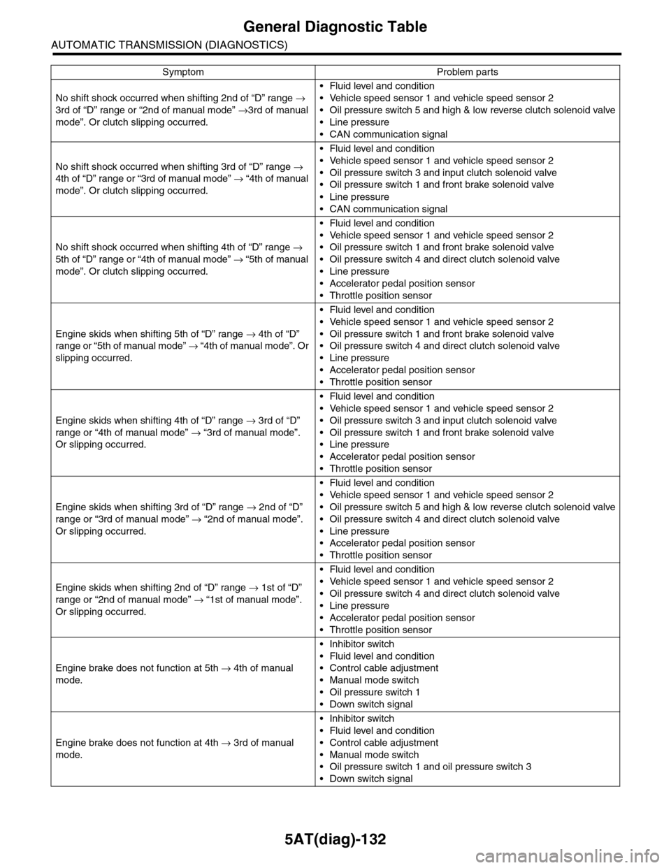
General Diagnostic Table
AUTOMATIC TRANSMISSION (DIAGNOSTICS)
No shift shock occurred when shifting 2nd of “D” range →
3rd of “D” range or “2nd of manual mode” →3rd of manual
mode”. Or clutch slipping occurred.
•Fluid level and condition
•Vehicle speed sensor 1 and vehicle speed sensor 2
•Oil pressure switch 5 and high & low reverse clutch solenoid valve
•Line pressure
•CAN communication signal
No shift shock occurred when shifting 3rd of “D” range →
4th of “D” range or “3rd of manual mode” → “4th of manual
mode”. Or clutch slipping occurred.
•Fluid level and condition
•Vehicle speed sensor 1 and vehicle speed sensor 2
•Oil pressure switch 3 and input clutch solenoid valve
•Oil pressure switch 1 and front brake solenoid valve
•Line pressure
•CAN communication signal
No shift shock occurred when shifting 4th of “D” range →
5th of “D” range or “4th of manual mode” → “5th of manual
mode”. Or clutch slipping occurred.
•Fluid level and condition
•Vehicle speed sensor 1 and vehicle speed sensor 2
•Oil pressure switch 1 and front brake solenoid valve
•Oil pressure switch 4 and direct clutch solenoid valve
•Line pressure
•Accelerator pedal position sensor
•Throttle position sensor
Engine skids when shifting 5th of “D” range → 4th of “D”
range or “5th of manual mode” → “ 4 t h of ma nua l mo d e” . O r
slipping occurred.
•Fluid level and condition
•Vehicle speed sensor 1 and vehicle speed sensor 2
•Oil pressure switch 1 and front brake solenoid valve
•Oil pressure switch 4 and direct clutch solenoid valve
•Line pressure
•Accelerator pedal position sensor
•Throttle position sensor
Engine skids when shifting 4th of “D” range → 3rd of “D”
range or “4th of manual mode” → “3rd of manual mode”.
Or slipping occurred.
•Fluid level and condition
•Vehicle speed sensor 1 and vehicle speed sensor 2
•Oil pressure switch 3 and input clutch solenoid valve
•Oil pressure switch 1 and front brake solenoid valve
•Line pressure
•Accelerator pedal position sensor
•Throttle position sensor
Engine skids when shifting 3rd of “D” range → 2nd of “D”
range or “3rd of manual mode” → “2nd of manual mode”.
Or slipping occurred.
•Fluid level and condition
•Vehicle speed sensor 1 and vehicle speed sensor 2
•Oil pressure switch 5 and high & low reverse clutch solenoid valve
•Oil pressure switch 4 and direct clutch solenoid valve
•Line pressure
•Accelerator pedal position sensor
•Throttle position sensor
Engine skids when shifting 2nd of “D” range → 1st of “D”
range or “2nd of manual mode” → “1st of manual mode”.
Or slipping occurred.
•Fluid level and condition
•Vehicle speed sensor 1 and vehicle speed sensor 2
•Oil pressure switch 4 and direct clutch solenoid valve
•Line pressure
•Accelerator pedal position sensor
•Throttle position sensor
Engine brake does not function at 5th → 4th of manual
mode.
•Inhibitor switch
•Fluid level and condition
•Control cable adjustment
•Manual mode switch
•Oil pressure switch 1
•Down switch signal
Engine brake does not function at 4th → 3rd of manual
mode.
•Inhibitor switch
•Fluid level and condition
•Control cable adjustment
•Manual mode switch
•Oil pressure switch 1 and oil pressure switch 3
•Down switch signal
Symptom Problem parts
Page 2250 of 2453
5AT(diag)-133
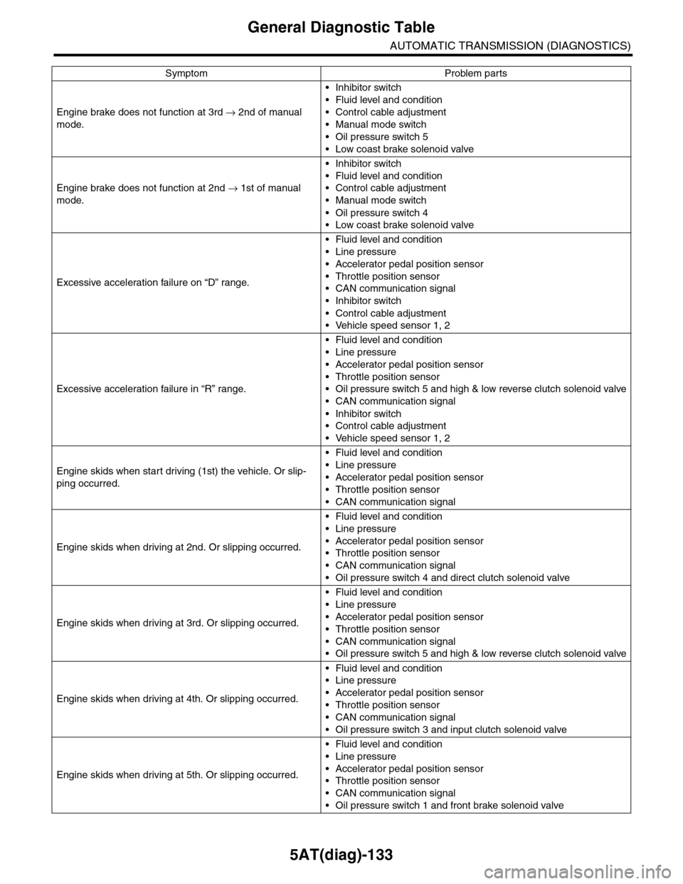
General Diagnostic Table
AUTOMATIC TRANSMISSION (DIAGNOSTICS)
Engine brake does not function at 3rd → 2nd of manual
mode.
•Inhibitor switch
•Fluid level and condition
•Control cable adjustment
•Manual mode switch
•Oil pressure switch 5
•Low coast brake solenoid valve
Engine brake does not function at 2nd → 1st of manual
mode.
•Inhibitor switch
•Fluid level and condition
•Control cable adjustment
•Manual mode switch
•Oil pressure switch 4
•Low coast brake solenoid valve
Excessive acceleration failure on “D” range.
•Fluid level and condition
•Line pressure
•Accelerator pedal position sensor
•Throttle position sensor
•CAN communication signal
•Inhibitor switch
•Control cable adjustment
•Vehicle speed sensor 1, 2
Excessive acceleration failure in “R” range.
•Fluid level and condition
•Line pressure
•Accelerator pedal position sensor
•Throttle position sensor
•Oil pressure switch 5 and high & low reverse clutch solenoid valve
•CAN communication signal
•Inhibitor switch
•Control cable adjustment
•Vehicle speed sensor 1, 2
Engine skids when start driving (1st) the vehicle. Or slip-
ping occurred.
•Fluid level and condition
•Line pressure
•Accelerator pedal position sensor
•Throttle position sensor
•CAN communication signal
Engine skids when driving at 2nd. Or slipping occurred.
•Fluid level and condition
•Line pressure
•Accelerator pedal position sensor
•Throttle position sensor
•CAN communication signal
•Oil pressure switch 4 and direct clutch solenoid valve
Engine skids when driving at 3rd. Or slipping occurred.
•Fluid level and condition
•Line pressure
•Accelerator pedal position sensor
•Throttle position sensor
•CAN communication signal
•Oil pressure switch 5 and high & low reverse clutch solenoid valve
Engine skids when driving at 4th. Or slipping occurred.
•Fluid level and condition
•Line pressure
•Accelerator pedal position sensor
•Throttle position sensor
•CAN communication signal
•Oil pressure switch 3 and input clutch solenoid valve
Engine skids when driving at 5th. Or slipping occurred.
•Fluid level and condition
•Line pressure
•Accelerator pedal position sensor
•Throttle position sensor
•CAN communication signal
•Oil pressure switch 1 and front brake solenoid valve
Symptom Problem parts
Page 2251 of 2453
5AT(diag)-134
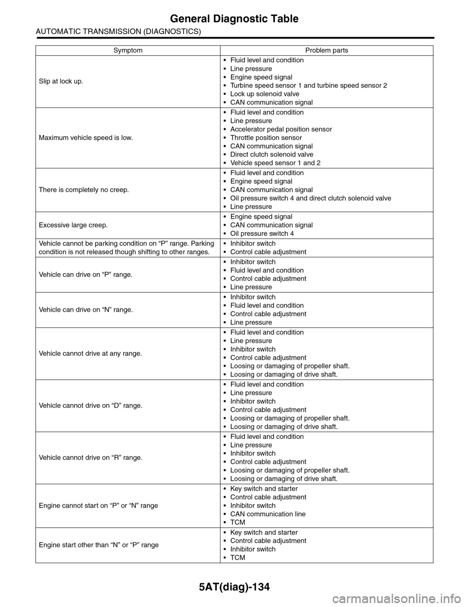
General Diagnostic Table
AUTOMATIC TRANSMISSION (DIAGNOSTICS)
Slip at lock up.
•Fluid level and condition
•Line pressure
•Engine speed signal
•Turbine speed sensor 1 and turbine speed sensor 2
•Lock up solenoid valve
•CAN communication signal
Maximum vehicle speed is low.
•Fluid level and condition
•Line pressure
•Accelerator pedal position sensor
•Throttle position sensor
•CAN communication signal
•Direct clutch solenoid valve
•Vehicle speed sensor 1 and 2
There is completely no creep.
•Fluid level and condition
•Engine speed signal
•CAN communication signal
•Oil pressure switch 4 and direct clutch solenoid valve
•Line pressure
Excessive large creep.
•Engine speed signal
•CAN communication signal
•Oil pressure switch 4
Ve h i c l e c a n n o t b e p a r k i n g c o n d i t i o n o n “ P ” r a n g e . Pa r k i n g
condition is not released though shifting to other ranges.
•Inhibitor switch
•Control cable adjustment
Ve h i c l e c a n d r i v e o n “ P ” r a n g e .
•Inhibitor switch
•Fluid level and condition
•Control cable adjustment
•Line pressure
Ve h i c l e c a n d r i v e o n “ N ” r a n g e .
•Inhibitor switch
•Fluid level and condition
•Control cable adjustment
•Line pressure
Ve h i c l e c a n n o t d r i v e a t a n y r a n g e .
•Fluid level and condition
•Line pressure
•Inhibitor switch
•Control cable adjustment
•Loosing or damaging of propeller shaft.
•Loosing or damaging of drive shaft.
Ve h i c l e c a n n o t d r i v e o n “ D ” r a n g e .
•Fluid level and condition
•Line pressure
•Inhibitor switch
•Control cable adjustment
•Loosing or damaging of propeller shaft.
•Loosing or damaging of drive shaft.
Ve h i c l e c a n n o t d r i v e o n “ R ” r a n g e .
•Fluid level and condition
•Line pressure
•Inhibitor switch
•Control cable adjustment
•Loosing or damaging of propeller shaft.
•Loosing or damaging of drive shaft.
Engine cannot start on “P” or “N” range
•Key switch and starter
•Control cable adjustment
•Inhibitor switch
•CAN communication line
•TCM
Engine start other than “N” or “P” range
•Key switch and starter
•Control cable adjustment
•Inhibitor switch
•TCM
Symptom Problem parts
Page 2252 of 2453
5AT(diag)-135
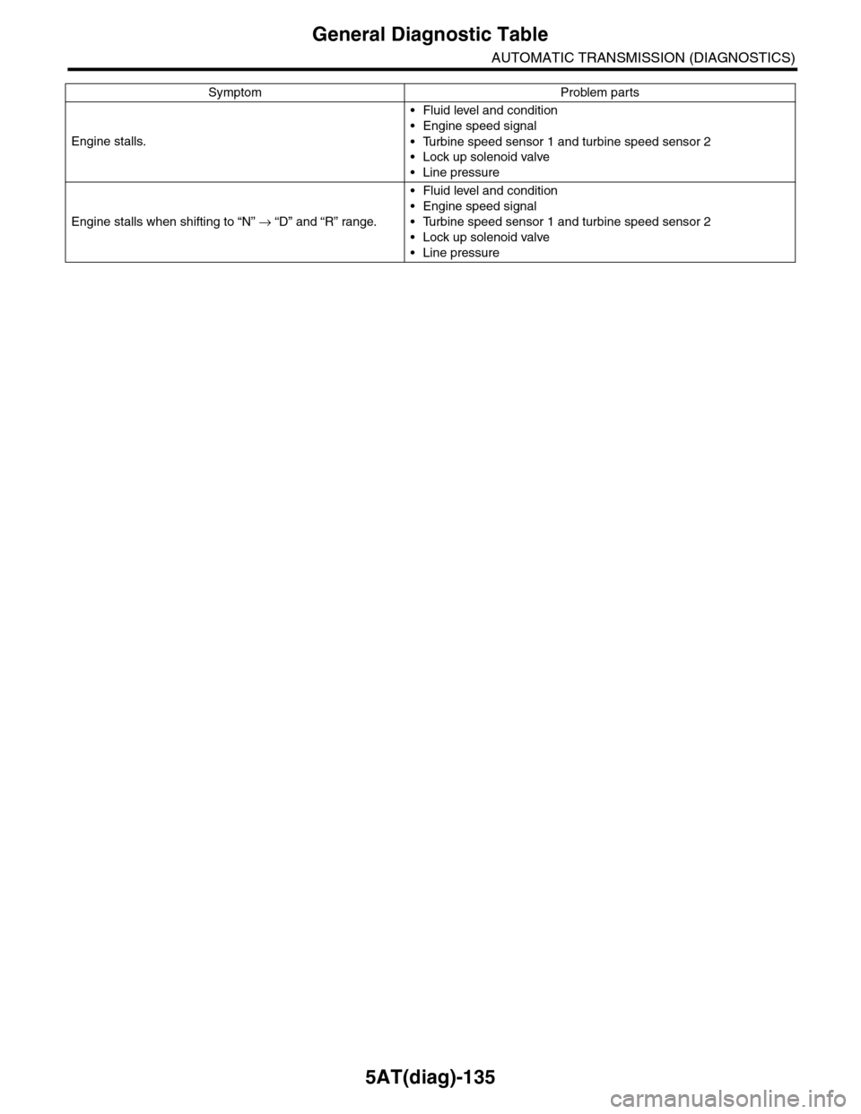
General Diagnostic Table
AUTOMATIC TRANSMISSION (DIAGNOSTICS)
Engine stalls.
•Fluid level and condition
•Engine speed signal
•Turbine speed sensor 1 and turbine speed sensor 2
•Lock up solenoid valve
•Line pressure
Engine stalls when shifting to “N” → “D” and “R” range.
•Fluid level and condition
•Engine speed signal
•Turbine speed sensor 1 and turbine speed sensor 2
•Lock up solenoid valve
•Line pressure
Symptom Problem parts
Page 2267 of 2453
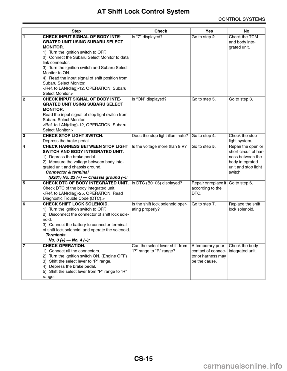
CS-15
AT Shift Lock Control System
CONTROL SYSTEMS
Step Check Yes No
1CHECK INPUT SIGNAL OF BODY INTE-
GRATED UNIT USING SUBARU SELECT
MONITOR.
1) Turn the ignition switch to OFF.
2) Connect the Subaru Select Monitor to data
link connector.
3) Turn the ignition switch and Subaru Select
Monitor to ON.
4) Read the input signal of shift position from
Subaru Select Monitor.
Is “7” displayed? Go to step 2.Check the TCM
and body inte-
grated unit.
2CHECK INPUT SIGNAL OF BODY INTE-
GRATED UNIT USING SUBARU SELECT
MONITOR.
Read the input signal of stop light switch from
Subaru Select Monitor.
Is “ON” displayed? Go to step 5.Go to step 3.
3CHECK STOP LIGHT SWITCH.
Depress the brake pedal.
Does the stop light illuminate? Go to step 4.Check the stop
light system.
4CHECK HARNESS BETWEEN STOP LIGHT
SWITCH AND BODY INTEGRATED UNIT.
1) Depress the brake pedal.
2) Measure the voltage between body inte-
grated unit and chassis ground.
Connector & terminal
(B281) No. 23 (+) — Chassis ground (–):
Is the voltage more than 9 V? Go to step 5.Repair the open or
short circuit of har-
ness between the
body integrated
unit and stop light
switch.
5CHECK DTC OF BODY INTEGRATED UNIT.
Check DTC of the body integrated unit.
Is DTC (B0106) displayed? Repair or replace it
according to the
DTC.
Go to step 6.
6CHECK SHIFT LOCK SOLENOID.
1) Turn the ignition switch to OFF.
2) Disconnect the connector of shift lock sole-
noid.
3) Connect the battery to connector terminal
of shift lock solenoid, and operate the solenoid.
Te r m i n a l s
No. 3 (+) — No. 4 (–):
Is the shift lock solenoid oper-
ating properly?
Go to step 7.Replace the shift
lock solenoid.
7CHECK OPERATION.
1) Connect all the connectors.
2) Turn the ignition switch ON. (Engine OFF)
3) Shift the select lever to “P” range.
4) Depress the brake pedal.
5) Shift the select lever from “P” range to “R”
range.
Can the select lever shift from
“P” range to “R” range?
A temporary poor
contact of connec-
tor or harness may
be the cause.
Check the body
integrated unit.
Page 2272 of 2453
CS-20
Select Lever
CONTROL SYSTEMS
3) Install the shift select cable onto select lever.
4) Install the center console.
5) Install the console box.
6) Shift the select lever to “N” range.
7) Lift–up the vehicle.
8) Shift the range select lever to the “N” range.
9) Secure the cable to the bracket.
10) Adjust the select cable position.
11) After the completion of adjustment, confirm that
the select lever operates properly at all range posi-
tions.
12) Install the heat shield cover.
13) Install the rear exhaust pipe and muffler.
Pipe.>
14) Inspect the following items. When a malfunc-
tion is found in the inspection, adjust the select ca-
ble.
(1) Engine starts when the select lever is in “P”
and “N” range, but not in other ranges.
(2) Back-up light illuminates when the select le-
ver is in the “R” range, but not in other ranges.
(3) Select lever and indicator positions are
matched.
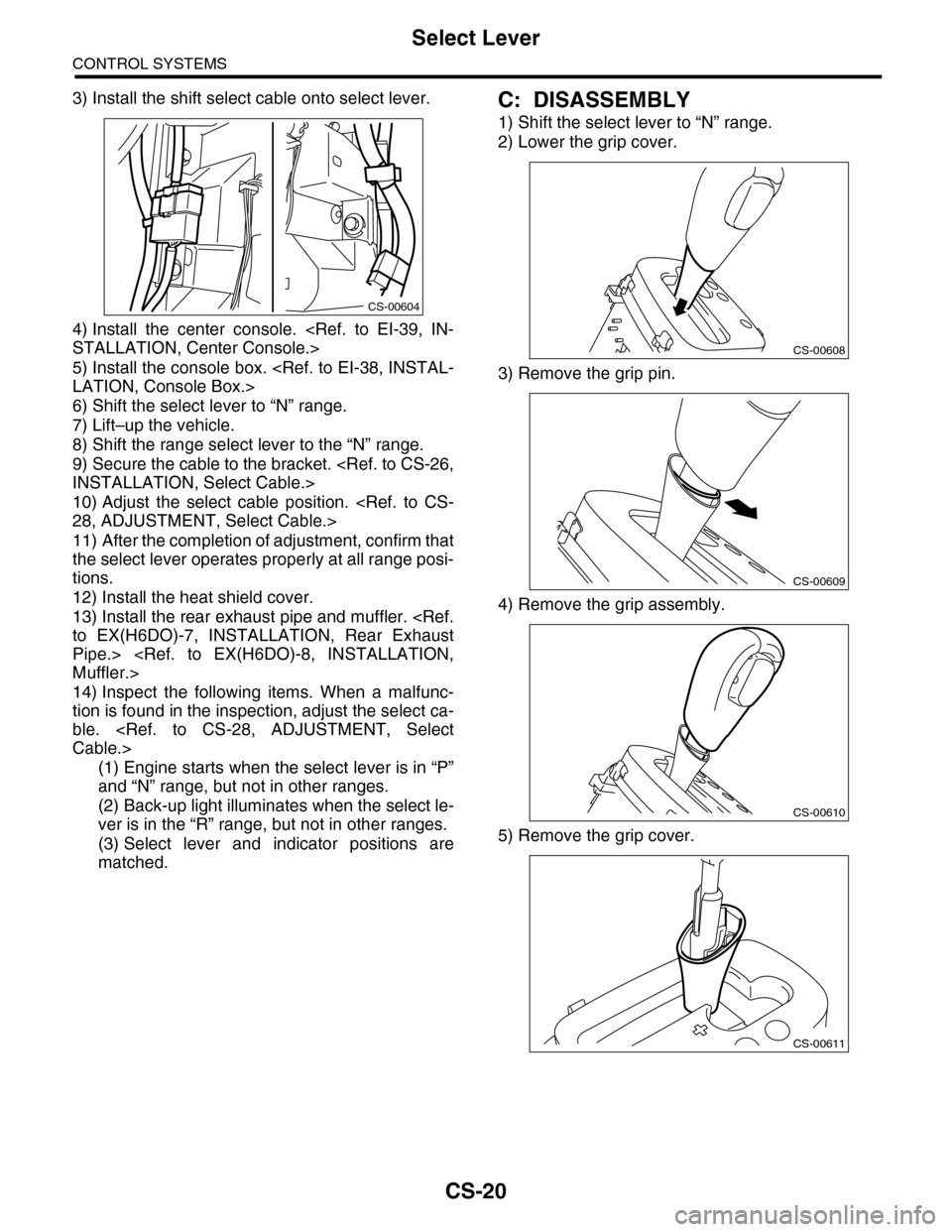
C: DISASSEMBLY
1) Shift the select lever to “N” range.
2) Lower the grip cover.
3) Remove the grip pin.
4) Remove the grip assembly.
5) Remove the grip cover.
CS-00604
CS-00608
CS-00609
CS-00610
CS-00611
Page 2291 of 2453
WI-7
Basic Diagnostic Procedure
WIRING SYSTEM
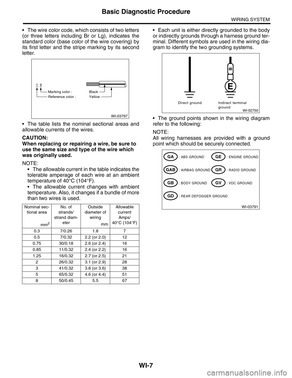
•The wire color code, which consists of two letters
(or three letters including Br or Lg), indicates the
standard color (base color of the wire covering) by
its first letter and the stripe marking by its second
letter.
•The table lists the nominal sectional areas and
allowable currents of the wires.
CAUTION:
When replacing or repairing a wire, be sure to
use the same size and type of the wire which
was originally used.
NOTE:
•The allowable current in the table indicates the
tolerable amperage of each wire at an ambient
temperature of 40°C (104°F).
•The allowable current changes with ambient
temperature. Also, it changes if a bundle of more
than two wires is used.
•Each unit is either directly grounded to the body
or indirectly grounds through a harness ground ter-
minal. Different symbols are used in the wiring dia-
gram to identify the two grounding systems.
•The ground points shown in the wiring diagram
refer to the following:
NOTE:
All wiring harnesses are provided with a ground
point which should be securely connected.
Nominal sec-
tional area
No. of
strands/
strand diam-
eter
Outside
diameter of
wiring
Allowable
current
Amps/
40°C (104°F)mm2mm
0.3 7/0.26 1.8 7
0.5 7/0.32 2.2 (or 2.0) 12
0.75 30/0.18 2.6 (or 2.4) 16
0.85 11/0.32 2.4 (or 2.2) 16
1.25 16/0.32 2.7 (or 2.5) 21
226/0.323.1 (or 2.9)28
341/0.323.8 (or 3.6)38
565/0.324.6 (or 4.4)51
850/0.455.5 67
WI-03797
YB
BlackMarking color :
Reference color : Yellow
WI-02750
Direct ground Indirect terminalground
B
WI-03791
: ABS GROUNDGA
: AIRBAG GROUNDGAB
: BODY GROUNDGB
: ENGINE GROUNDGE
: RADIO GROUNDGR
: VDC GROUNDGV
: REAR DEFOGGER GROUNDGD
Page 2293 of 2453
WI-9
Basic Diagnostic Procedure
WIRING SYSTEM
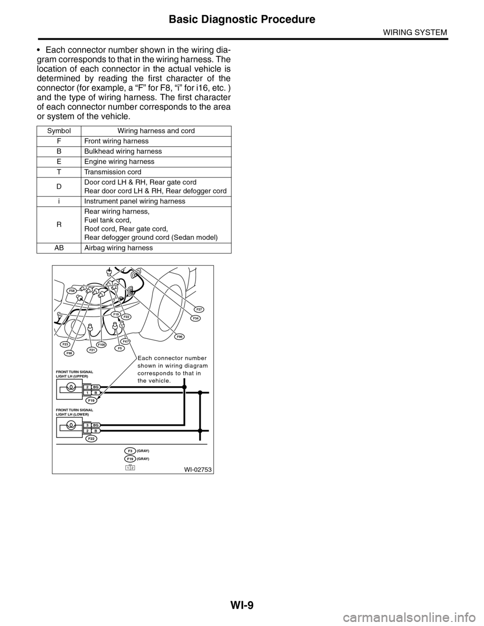
•Each connector number shown in the wiring dia-
gram corresponds to that in the wiring harness. The
location of each connector in the actual vehicle is
determined by reading the first character of the
connector (for example, a “F” for F8, “i” for i16, etc. )
and the type of wiring harness. The first character
of each connector number corresponds to the area
or system of the vehicle.
Symbol Wiring harness and cord
FFront wiring harness
BBulkhead wiring harness
EEngine wiring harness
TTransmission cord
DDoor cord LH & RH, Rear gate cord
Rear door cord LH & RH, Rear defogger cord
iInstrument panel wiring harness
R
Rear wiring harness,
Fuel tank cord,
Roof cord, Rear gate cord,
Rear defogger ground cord (Sedan model)
AB Airbag wiring harness
F23
F98F21
F58
F100F5
F27
F47
F34F19F22
F96
WI-02753
Each connector number shown in wiring diagram corresponds to that in the vehicle.
F19
FRONT TURN SIGNAL LIGHT LH (UPPER)
BG2B1
F22
FRONT TURN SIGNAL LIGHT LH (LOWER)
BG3B2
(GRAY)F3(GRAY)F19
12