Page 9 of 179

87B-9
MR-413-X44-87B000$192.mif
V5
87B
PASSENGER COMPARTMENT CONNECTION UNIT
Fault finding - Role of components
GENERAL OPERATION
The UCH is involved in the following five functions (shared between several computers):
–Access-security function
This function is divided into three sub-functions: Access, Protection and Starting (see 82D, Access - Safety).
–Air heating and manual air conditioning function
This function is divided into four sub-functions, which are: User selection, Heating, Cold loop and Passenger
compartment ventilation (see 61A, Heating and see 62C, Manual air conditioning).
In this function, the UCH manages the heated rear screen operation indicator lights, heating controls and air
conditioning activation requests, by sending requests to the engine management computer:
–In the case of a vehicle fitted with manual air conditioning, by pressing on the air conditioning button.
–In the case of a vehicle fitted with climate control, by request from the user or the climate control computer in
automatic mode.
–Wiping function
This function is divided into two sub-functions, which are: Wiper control and Wiper power (see 85A,
Wiping-washing).
–Lighting Function
This function is divided into two sub-functions, which are: Lighting control and Lighting power (see 80D, Lighting).
–Energy management function
Note: There is no UPC on this vehicle; this function is managed by the UCH.
The system is composed of the UCH which stores the programming for electrical energy management, the starter,
the battery, and the alternator controlled via a BSS connection.
The role of this system is:
●to ensure electrical energy is supplied to the vehicle whilst respecting the dynamic performance
constraints of the engine and transmission assembly,
●to control alternator loading* and load shedding** during engine management authorisation or variation of
the electrical load,
●to ensure the quality of the on board network voltage in terms of the voltage level and variation,
●to optimise the battery charge by applying a voltage to its terminals correlating to its initial charge status
(in sleep mode) and to its internal temperature,
●to inform the engine management about the mechanical power taken from the accessories pulley, the
alternator charge rate and the rotor excitation current value,
●to run fault finding on the charging circuit: “Battery” warning light display.
*loading: This operation consists of transferring control of the vehicle's electrical consumption from the battery
to the alternator.
**load shedding: This operation consists of involving the battery in the vehicle's general electric power balance.
MR-413-X44-87B000$192.mif
UCH
Vdiag No.: 44
Page 10 of 179

87B-10
MR-413-X44-87B000$192.mif
V5
UCH
Vdiag No.: 44PASSENGER COMPARTMENT CONNECTION UNIT
Fault finding - Role of components87B
–Energy management function
Role of BSS connection:
This bidirectional connection located between the UCH and the alternator circulates the following signals:
–Signals sent by the alternator: rotor current value, alternator charge value and electrical, thermal and
mechanical fault statuses.
–Signals sent by the UCH to the alternator: voltage setpoint, rail setpoint and rail inhibition.
Role of the DF terminal:
The signal circulating in the DF terminal is the alternator charge signal (displayed using PR073 "Alternator
charge signal") which is used to adapt the alternator supply to the demands of the electrical consumers
(such as the passenger compartment heating resistors, heated rear screen, etc.).
Depending on the battery charge status, the operating phase and the battery temperature, the UCH determines what
the voltage across the battery terminals should be.
When the battery charge drops, and PR076 Battery voltage after rest decreases, the UCH can temporarily
increase PR075 Alternator setpoint voltage by 1 V for a period of 15 minutes after switching on + after ignition
feed.
Before and during starting, PR075 Alternator setpoint voltage is fixed at 10.7 V.
A maximum of 30 seconds after the engine has started, the UCH sets PR075 Alternator setpoint voltage to the
optimum value calculated.
The injection computer can also control the alternator regulation voltage. The injection computer sends the
maximum authorised power delivered by the engine, to the UCH via the multiplex network. If this power supplied by
the engine is less than the power consumed by the alternator, the UCH reduces the PR075 Alternator setpoint
voltage.
The battery warning light will flash if a low battery charge is detected (no-load voltage less than 12.2 V: voltage
measured during technical use) for the first 12 miles (20 kms), then the warning light stops flashing. Also, the magic
eye of the battery (the hydrometer) is black.
–Access - Security function (see 82D, Access - Security, Role of components).
–Heating and manual air conditioning function (see 61A, Heating, Role of components and 62C, Manual air
conditioning, Role of components).
–Wiping function (see 85A, Washing wiping, Role of components).
–Lighting function (see 80D, Lighting, Role of components). Note:
At the time of user activation, if the mileage is less than 12 miles (20 kms) the charge status is used to display a
warning: this ensures that vehicles are delivered with correct batteries.
Page 11 of 179

87B-11
MR-413-X44-87B000$192.mif
V5
UCH
Vdiag No.: 44PASSENGER COMPARTMENT CONNECTION UNIT
Fault finding - Role of components87B
Functions managed by the different UCH ranges on the New Twingo:
* CPE: Electric central door locking
* CAR: Automatic locking when drivingL1
Entry levelL2
Mid-rangeL3
Top of the
range
UCH reprogrammingXX X
Multiplex connectionXX X
Fault findingXX X
Access - Protection X X X
Transponder keyX
Transponder and radiofrequency keyXX
Engine immobiliserXX X
+ Accessories feed controlXX X
Alarm management (predisposition)XX
Locking and unlocking using electric central door locking buttonXX
DeadlockingX
Locking when driving (CAR*)XX
Automatic unlocking (in the event of impact)XX
Engine thermal protectionXX X
Automatic re-lockingXX
One-touch electric windowsX
Tailgate electric lockXX X
Tailgate opening switchXX X
Tailgate locking switch (with key)X
Air conditioning
Electric heated rear screen managementXX X
Air conditioning request managementXX
Automatic climate control management (via CAN network)XX
External temperature managementXX
Page 12 of 179

87B-12
MR-413-X44-87B000$192.mif
V5
UCH
Vdiag No.: 44PASSENGER COMPARTMENT CONNECTION UNIT
Fault finding - Role of components87B
CONTINUED (Functions managed by the different UCH ranges on the New Twingo):
L1
Entry levelL2
Mid-rangeL3
Top of the
range
Lighting
Exterior lighting
Side, dipped beam, headlightsX
Direction indicators and hazard warning lightsXX X
One-touch front fog lightsX
One-touch rear fog lightsX
Lights on warning lightXX X
Hazard warning lights when decelerating hardXX X
Illumination of hazard warning lights when airbag triggeredXX X
Illumination of indicators when locking/unlockingXX
Automatic lighting when driving and stationaryX
Delayed extinction of headlights when stationary X
Daytime running lights onX
Lights switch off when driver's door openedX
Interior lighting
Interior lights supply (no gradual dimming function)X
Interior lights supply (gradual dimming)XX
Wipers
Windscreen wipers managementXX X
Automatic management of front wipers with rain sensorX
Rear wipersXX X
Windscreen and rear screen washersXX X
Energy management
Starter managementXX X
Controlled alternator (BSS connection)XX X
Page 13 of 179

87B-13
MR-413-X44-87B000$240.mif
V5
87B
PASSENGER COMPARTMENT CONNECTION UNIT
Fault finding - Replacement of components
When replacing the UCH (see MR 411, Mechanical systems, 87B, Passenger compartment connection unit).
If replacing the computer, carry out the programming and configuration operations described (see configurations
and programming).
The order of programming and configuration operations is as follows:
1 - Write the VIN, using command VP004 Write VIN.
2 - Program the UCH using command SC004 UCH programming.
3 - Configuration of the UCH (in the Configuration and programming menu) using the following commands:
CF031 Calibration,
CF019 Type of heating and air conditioning system,
CF028 Engine type,
CF171 Temperature display,
CF029 External temperature sensor,
CF173 One-touch windows/sunroof (SR)*.
CF032 See-me-home lighting,
CF021 Front fog lights,
CF014 Daytime running lights
CF193 Automatic headlight function,
CF194 Automatic wiping function,
CF035 Rain/light sensor,
CF191 Wiper intermittent speed ring,
CF024 Hazard warning lights activated by ABS,
CF108 Locking via the RAID,
CF009 Deadlocking,
CF192 Central door locking,
CF195 Type of key,
CF229 Alarm.
4 - Key allocation, using command SC015 Key allocation.
5 - Configuration of the multiplex network is used to define (in the UCH) the different computers present and which
support fault finding on the multiplex network.
* TO: Sunroof.
MR-413-X44-87B000$240.mif
UCH
Vdiag No.: 44
Page 14 of 179

87B-14
MR-413-X44-87B000$288.mif
V5
87B
PASSENGER COMPARTMENT CONNECTION UNIT
Fault finding - Configurations and programming
Use this command only with a new and blank UCH.
A new UCH is not coded and is therefore not assigned to the vehicle; once it is fitted on the vehicle, it must be
programmed to assign it to the vehicle.
To carry out this programming, always use a key belonging to the vehicle (allocated to the old UCH).
Thereare two programming methods: "Not connected" to the code server mode and "connected" to the code server
mode.
-In"not connected" mode, the CLIP diagnostic tool supplies a programming key and the user enters the im mobiliser
code.
-In"connected" mode, the CLIP diagnostic tool automatically exchanges the programming key and the immobiliser
code.
Before starting this operation, make sure that there are no components capable of interfering with the
electromagnetic field (e.g.: CB (Citizen Band), mobile phone, etc.).SC004
PROGRAMMING THE UCH
Equipment required
CLIP
Note:
After replacing just the UCH, no operation needs to be carried out on the injection and electric power-assisted
steering computers.
The computers keep the same immobiliser code.
IMPORTANT
When the UCH programming procedure is successfully completed, the UCH is no longer blank and is
permanently assigned to the vehicle. It will not work on another vehicle.
IMPORTANT
When the programming operation is complete, only remove the key once theProgrammingcompletemessage is
displayed on the screen. Otherwise, programming has failed and the UCH cannot be used.
IMPORTANT
In "not connected" mode, once the tool has issued the programming key, the user has a limited amount of time in
which to enter the immobiliser code.
If this time expires, the CLIP diagnostic tool displays the message "Time expired. Restart the procedure''.
IMPORTANT
In "connected" mode, the exchange of the programming key and the entry of the immobiliser code is done
automatically. If the connection parameters are not met, "connected" mode switches automatically to "not
connected" mode.
MR-413-X44-87B000$288.mif
UCH
Vdiag No.: 44
Page 15 of 179

87B-15
MR-413-X44-87B000$288.mif
V5
UCH
Vdiag No.: 44PASSENGER COMPARTMENT CONNECTION UNIT
Fault finding - Configurations and programming87B
UCH programming procedure
–Establish dialogue with the UCH.
–Select the "Repair mode" menu.
–Select the Secure programming menu.
–Select line SC004 Program UCH.
Follow the instructions on the CLIP diagnostic tool.
In "not connected" mode, when the CLIP diagnostic tool displays the programming key, make a note of this key
and the VIN.
To obtain the immobiliser code, see Technical Note 5037A, Code delivery procedure.
Operations to be carried out after programming the UCH
➡ Enter the vehicle's VIN to the computer using command VP004 Enter VIN.
Make sure that all the keys can lock and start the vehicle.
➡ After programming the UCH, allocate all the keys using command SC015 Allocate key.
➡ Configure the equipment as present or not present on the vehicle using the commands
(see Configurations and Programming). SC004
CONTINUED
IMPORTANT
Do not interrupt the procedure when it is in progress.
If it is interrupted, restart the procedure; a new programming key will be displayed.
IMPORTANT
In "not connected" mode, the programming key can only be used for a limited amount of time, as indicated by the
CLIP diagnostic tool. After this time, the programming key and associated immobiliser code are no longer valid.
The operation must be restarted from the beginning.
Page 16 of 179

87B-16
MR-413-X44-87B000$288.mif
V5
UCH
Vdiag No.: 44PASSENGER COMPARTMENT CONNECTION UNIT
Fault finding - Configurations and programming87B
This key allocation operation enables you to assign keys to the vehicle.
To add one or more keys, replace one or more keys, de-allocate one or more keys (in the event of theft for example).
There are two programming methods: "Not connected" to the code server mode and "connected" to the code server
mode.
-In "not connected" mode, the CLIP diagnostic tool supplies a programming key and the user enters the
immobiliser code.
-In "connected" mode, the CLIP diagnostic tool automatically exchanges the programming key and the immobiliser
code.
Before starting this operation, make sure that there are no components capable of interfering with the
electromagnetic field (e.g.: CB (Citizen Band), mobile phone, etc.).
Only a non blank UCH can be programmed with keys.
With this system it is not possible to replace some components, such as the UCH and the key as these parts are sold
blank and uncoded.SC015
KEY ALLOCATION
Equipment required
CLIP
IMPORTANT
It is not possible to allocate more than two blank keys per operation.
If more than two keys must be allocated: program 2 blank keys then repeat the procedure with all the keys.
WARNING
If not all of the keys are available, all the keys will have to be reallocated later. Keys not inserted will no longer be
allocated to this vehicle.
WARNING
Only cards which have been ordered for the vehicle concerned or the vehicle's old cards can be inserted.
IMPORTANT
When the programming operation is complete, only remove the key once the Remove the key message is
displayed on the screen. Otherwise the programming operation has failed and the key will be unusable.
WARNING
When the tool issues the programming key, the user has a limited time in which to enter the immobiliser code.
If the time has elapsed, the Clip tool displays the message: Time elapsed.Restart the procedure.
 1
1 2
2 3
3 4
4 5
5 6
6 7
7 8
8 9
9 10
10 11
11 12
12 13
13 14
14 15
15 16
16 17
17 18
18 19
19 20
20 21
21 22
22 23
23 24
24 25
25 26
26 27
27 28
28 29
29 30
30 31
31 32
32 33
33 34
34 35
35 36
36 37
37 38
38 39
39 40
40 41
41 42
42 43
43 44
44 45
45 46
46 47
47 48
48 49
49 50
50 51
51 52
52 53
53 54
54 55
55 56
56 57
57 58
58 59
59 60
60 61
61 62
62 63
63 64
64 65
65 66
66 67
67 68
68 69
69 70
70 71
71 72
72 73
73 74
74 75
75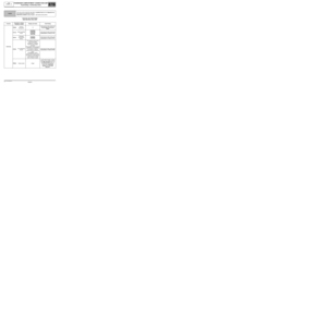 76
76 77
77 78
78 79
79 80
80 81
81 82
82 83
83 84
84 85
85 86
86 87
87 88
88 89
89 90
90 91
91 92
92 93
93 94
94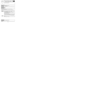 95
95 96
96 97
97 98
98 99
99 100
100 101
101 102
102 103
103 104
104 105
105 106
106 107
107 108
108 109
109 110
110 111
111 112
112 113
113 114
114 115
115 116
116 117
117 118
118 119
119 120
120 121
121 122
122 123
123 124
124 125
125 126
126 127
127 128
128 129
129 130
130 131
131 132
132 133
133 134
134 135
135 136
136 137
137 138
138 139
139 140
140 141
141 142
142 143
143 144
144 145
145 146
146 147
147 148
148 149
149 150
150 151
151 152
152 153
153 154
154 155
155 156
156 157
157 158
158 159
159 160
160 161
161 162
162 163
163 164
164 165
165 166
166 167
167 168
168 169
169 170
170 171
171 172
172 173
173 174
174 175
175 176
176 177
177 178
178