Page 169 of 179

87B -169
MR-413-X44-87B000$912.mif
V5
PASSENGER COMPARTMENT CONNECTION UNIT
Fault finding - Fault Finding Chart
UCH
Vdiag No.: 44
87B
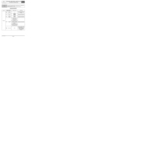
ALP 26 Accessories feed not activated
NOTESCheck the battery voltage (see 80A Battery).
Start the fault finding procedure with the ignition off and the vehicle locked.
When the vehicle is unlocked, the instrument panel should light up for a moment.
Otherwise, carry out fault finding on the multiplex network (see 88B, Multiplexing).
Check the operation of status ET239 "Ignition switch position".
Check the presence and condition of fuses F27 (5 A), depending on the equipment, and F29 (15 A) on the
passenger compartment fuse and relay box (component code 1016).
Replace the fuse if necessary.
Check the condition and connection of the connectors of components 645 and 1016 (tabs bent, oxidised or
broken).
Check for + accessories feed on connection SP2 (for vehicles fitted with a manual gearbox) or SP15 (for
vehicles fitted with a sequential gearbox) of component 645.
Check for earth on connection NAM of component 645.
Check for earth on the connection MAM (for right-hand drive vehicles) or MAN (for left-hand drive vehicles) of
component 645.
If the connection or connections are faulty and there is a repair procedure (see Technical Note 6015A, Electrical
wiring repair, Wiring: Precautions for repair), repair the wiring, otherwise replace it.
Check the insulation, continuity and the absence of interference resistance of the following connections:
Connection code SP2 between components 645 and 1016.
Connection code SP15 between components 645 and 1016.
Connection code MAN or MAM between component 645 and earth MAN or MAM (depending on the driving
layout; right-hand or left-hand drive).
If the connection or connections are faulty and there is a repair procedure (see Technical Note 6015A, Electrical
wiring repair, Wiring: Precautions for repair), repair the wiring, otherwise replace it.
If the fault is still present, contact the Techline.
AFTER REPAIRCarry out a complete check using the diagnostic tool.
UCH_V44_ALP26
Page 170 of 179
87B -170
MR-413-X44-87B000$912.mif
V5
PASSENGER COMPARTMENT CONNECTION UNIT
Fault finding - Fault Finding Chart
UCH
Vdiag No.: 44
87B
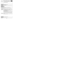
ALP 27No + after ignition feed activation or the + after ignition feed stays
jammed
NOTESCheck the battery voltage (see 80A Battery).
Check for faults using the diagnostic tool. Deal with the other faults first.
The + accessories feed activation function should be working; if not deal with ALP 26
Accessories feed not activated first.
Make sure that status ET239 Ignition switch position is working.
Make sure that status ET239 Ignition switch position
is workingApply the interpretation of the status if necessary.
Run a multiplex network test (see 88B, Multiplexing).
See 13B, Diesel injection or see 17B, Petrol injection.
AFTER REPAIRCarry out a complete check using the diagnostic tool.
UCH_V44_ALP27
Page 171 of 179

87B -171
MR-413-X44-87B000$912.mif
V5
PASSENGER COMPARTMENT CONNECTION UNIT
Fault finding - Fault Finding Chart
UCH
Vdiag No.: 44
87B
ALP 28 Illumination of the "battery charge" warning light
NOTESCheck the battery voltage (see 80A Battery).
Check for faults using the diagnostic tool.
Deal with the other faults first.
Check with LC023 Engine type that the engine type configured matches the vehicle. Otherwise perform CF028
Engine type to modify the configuration.
IMPORTANT
The battery warning light can flash if a low battery charge is detected (no-load voltage less than 12.2 V: voltage
measured during technical use) for the first 12 miles (20 km), then the warning light stops flashing. Also, the magic
eye of the battery (the hydrometer) is black.
If a vehicle has been driven less than 12 miles (20 km), the battery warning light is flashing and the battery magic
eye (the hydrometer) is black, apply the following procedure:
-Recharge the battery for at least 6 hours. The battery must be disconnected (reconnection must be done to torque).
Note:
The battery must be recharged using a specific charger, which is listed in the "Garage Equipment" catalogue.
-After 6 hours, if the magic eye has not turned green, the battery must be replaced.
If the configuration is correct (see 80A Battery).
If the fault is still present, contact the Techline.
AFTER REPAIRCarry out a complete check using the diagnostic tool.
UCH_V44_ALP28
Page 172 of 179
87B -172
MR-413-X44-87B000$912.mif
V5
PASSENGER COMPARTMENT CONNECTION UNIT
Fault finding - Fault Finding Chart
UCH
Vdiag No.: 44
87B
ALP 29 Starter noisy
NOTESSpecial notes:
Check for faults using the diagnostic tool. Deal with the other faults first.
Use the W iring Diagrams Technical Note for New Twingo.
Check with LC023 Engine type that the engine type configured matches the vehicle. Otherwise perform CF028
Engine type to modify the configuration.
If the configuration is correct (see 16A Starting - Charging).
If the fault is still present, contact the Techline.
AFTER REPAIRCarry out a complete check using the diagnostic tool.
UCH_V44_ALP29
Page 173 of 179

87B -173
MR-413-X44-87B000$912.mif
V5
PASSENGER COMPARTMENT CONNECTION UNIT
Fault finding - Fault Finding Chart
UCH
Vdiag No.: 44
87B
ALP 30 Low light intensity
NOTESCheck the battery voltage (see 80A Battery).
Check for faults using the diagnostic tool. Deal with the other faults first.
With the engine running at idle speed, run command AC130 Alternator regulation.
–Wait 20 seconds.
–For 10 seconds the voltage of the alternator (component code 103) should be equal to 15 V ± 0.2 V, when
using a multimeter to measure on connection BPDA between components 103 and 645.
–Wait 20 seconds.
–For 10 seconds the voltage of the alternator (component code 103) must be equal to 13 V ± 0.2 V when
measuring between the alternator terminal (component code103) and the earth on connection 2N using a
multimeter.
If the values measured are not correct, check the starting - charging circuit (see 16A Starting - Charging) and
check the battery (see 80A, Battery).
If the fault is still present, contact the Techline.
AFTER REPAIRCarry out a complete check using the diagnostic tool.
UCH_V44_ALP30
Page 174 of 179
87B -174
MR-413-X44-87B000$912.mif
V5
PASSENGER COMPARTMENT CONNECTION UNIT
Fault finding - Fault Finding Chart
UCH
Vdiag No.: 44
87B
* SR.: Sunroof
ALP 31 The sunroof does not work
NOTESOnly consult this customer complaint after a complete check using the diagnostic
tool and after having applied the interpretation of DF065 Electric window
authorisation connection.
Check that nothing is obstructing the operation of the sunroof.
Repair if necessary.
Check the condition of fuses F26 (20 A) and F31 (30 A) in the passenger compartment fuse and relay box
(component code 1016).
Replace the fuse if necessary.
For vehicles equipped with a sunroof, check that the LC070 One-touch windows/SR* is With. Otherwise,
perform CF173 One-touch windows/SR*.
If CF173 One-touch windows/SR* is With, (see MR 411 Mechanical, 87D Electric windows - Sunroof).
AFTER REPAIRCarry out a complete check using the diagnostic tool.
UCH_V44_ALP31
Page 175 of 179
87B -175
MR-413-X44-87B000$912.mif
V5
UCH
Vdiag No.: 44PASSENGER COMPARTMENT CONNECTION UNIT
Fault finding - Fault Finding Chart87B
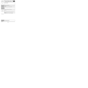
ALP 32 No information in the key
NOTESOnly address this customer complaint after a complete check with the diagnostic
tool.
Read configuration LC089 Memory key
function.
Is the configuration YES?
YES
Is status ET407 YES?
Status accessible in SC018 Key test.
YES
Replace the key.
NOThe vehicle is not equipped with the
memory key function.
It is normal for the key not to contain any
information about the vehicle.
NOThe key does not have the memory key
function.
It is normal for the key not to contain any
information about the vehicle.
If necessary, replace this key with
a memory key.
AFTER REPAIRCarry out a complete check using the diagnostic tool.
UCH_V44_ALP32
Page 176 of 179

87B -176
MR-413-X44-87B000$912.mif
V5
UCH
Vdiag No.: 44PASSENGER COMPARTMENT CONNECTION UNIT
Fault finding - Fault Finding Chart87B
ALP 33 No external temperature display
NOTESOnly address this customer complaint after a complete check with the diagnostic
tool.
Check that the temperature display works, use AC110 Temperature display.
Read configuration LC002 External
temperature sensor.
Is the configuration YES?
YES
Check that LC067 Temperature display is With. Otherwise perform
CF171 Temperature display.
Check the condition and connection of the PE2 40-track connector in the
UCH (component code 645) (tabs bent, broken, etc.).
If the connector is faulty and there is a repair method (see Te chnical Note
6015A, Repairing electrical wiring, Wiring: Precautions for repair),
repair the wiring, otherwise replace the wiring.
Check the continuity of the following connection:
Connection code 47Z between components 645 and 653.
If the connection is faulty and there is a repair procedure (see Technical
Note 6015A, Electrical wiring repair, Wiring: Precautions for repair),
repair the wiring, otherwise replace it.
If the connection is correct, replace the display. (See MR 411 Mechanical,
86A, Radio, Display: Removal - Refitting).
If the fault is still present, contact the Techline.
NOThe vehicle is not equipped with the
External temperature sensor function.
It is normal for the external temperature
not to be displayed.
UCH_V44_ALP33