Page 49 of 179

87B-49
MR-413-X44-87B000$384.mif
V5
PASSENGER COMPARTMENT CONNECTION UNIT
Fault finding - Interpretation of faults
UCH
Vdiag No.: 44
87B
DF097
CONTINUED
Check the windscreen wiper motor:
●Connection code 14A between components 212 and 645.
●Connection code 14B between components 212 and 645.
●Connection code 14C between components 212 and 645.
●Connection code MAS between component 212 and earth MAS.
If the connection or connections are faulty and there is a repair procedure (see Technical Note 6015A, Electrical
wiring repair, Wiring: Precautions for repair), repair the wiring, otherwise replace it.
Check the fitting of the windscreen wiper motor (component code 212).
Repair if necessary or replace the motor if it is faulty. (see MR 411, Mechanical systems, 85A, Washing -
wiping, Windscreen wiper motor: Removal - Refitting)
If the fault is still present, contact the Techline.
AFTER REPAIRCarry out another fault finding check on the system.
Clear the stored faults.
Deal with any other faults.
Page 50 of 179

87B-50
MR-413-X44-87B000$384.mif
V5
PASSENGER COMPARTMENT CONNECTION UNIT
Fault finding - Interpretation of faults
UCH
Vdiag No.: 44
87B
With automatic headlighting:DF098
PRESENT
OR
STORED
MAIN BEAM HEADLIGHT RELAY CONTROL CIRCUIT
CC.1 : Short circuit to + 12 volts
CC.0 : Open circuit or short circuit to earth
NOTESConditions for applying the fault finding procedure to stored faults:
The fault reappears after:
The ignition is switched on and the main beam headlights are activated.
OR
Running AC062 Main beam headlights
Note:
This fault only appears on vehicles fitted with automatic daytime running lights. Check
for the rain/light sensor (component code 1415) then:
–Check that the vehicle has a rain/light sensor (component code 1415).
–Check that LC044 "Rain/light sensor" displays "Present". If not, carry out -
CF035 "Rain/light sensor".
–Check that LC096 "Automatic wiper function" displays "With". If not, carry out
CF194 "Automatic wiper function".
–Check that LC095 "Automatic headlight function", displays "With". If not, carry
out CF193 "Automatic headlight function".
Check the presence and condition of fuses F15 (5 A), F25 (15 A), F32 (10 A) and F33 (10 A) on the passenger
compartment fuse and relay box (component code 1016).
Replace the fuse if necessary.
Check the presence and condition of the main beam headlights relay (component code 1574) (20A).
Replace the main beam headlights relay (component code 1574) if necessary.
Check the correct positioning and condition of the bulb concerned.
Replace the light if necessary.
Check the condition and connection of the light concerned (bent, oxidised, broken tabs).
Check the condition and connection of the UCH PE2 connectors (component code 645) (tabs bent, oxidised or
broken).
Check the condition and connection of the horn and lights switch connector (component code 209) (tabs bent,
oxidised, broken).
Check for + 12 V (when there is a main beam headlights request) on connection RPD of components 226 and
227. Check for an earth on connection MAR of component 226 and connection MAS on component 227.
If the connection or connections are faulty and there is a repair procedure (see Technical Note 6015A, Electrical
wiring repair, Wiring: Precautions for repair), repair the wiring, otherwise replace it.
AFTER REPAIRCarry out another fault finding check on the system.
Clear the stored faults.
Deal with any other faults.
UCH_V44_DF098
Page 51 of 179

87B-51
MR-413-X44-87B000$384.mif
V5
PASSENGER COMPARTMENT CONNECTION UNIT
Fault finding - Interpretation of faults
UCH
Vdiag No.: 44
87B
DF098
CONTINUED 1
Main beam headlights check:
Check the insulation, continuity and the absence of interference resistance on the following connections:
Front right-hand main beam headlight:
●Connection code RPD between components 226 and 1016.
●Connection code MAR between component 226 and earth MAR.
Front left-hand main beam headlight:
●Connection code RPG between components 227 and 1016.
Connection code MAS between component 227 and earth MAS.
Check for + 12 V (when main beam headlights are requested) on connection R of component 1574.
Check for + 12 V (when main beam headlights are requested) on connection 11A of component 1574. Check for
+ 12 V on connection BP11 of component 1574.
Main beam headlights relay check:
Check the insulation, continuity and the absence of interference resistance on the following connections:
●Connection code R between components 1016 and 1574.
●Connection code 11A between components 1574 and 645.
●Connection code BP11 between components 1574 and 597.
If the connection or connections are faulty and there is a repair procedure (see Technical Note 6015A, Electrical
wiring repair, Wiring: Precautions for repair), repair the wiring, otherwise replace it.
Checking the monolever (component code 209):
Check the insulation, continuity and the absence of interference resistance on the following connections:
Check between the monolever (component code 209) and the UCH:
●Connection code 11Q between components 645 and 209.
Hazard lights:
●Connection code 11R between components 209 and 654.
Check between the monolever (component code 209) and the passenger compartment fuse and relay box
(component code 1016):
●Connection code BPA2 between components 209 and 1016.
●Connection code BPA3 between components 209 and 1016.
●Connection code MAN (left-hand drive) or MAM (right-hand drive) between component 209 and the earth
MAN (left-hand drive) or MAM (right-hand drive).
If the connection or connections are faulty and there is a repair procedure (see Technical Note 6015A, Electrical
wiring repair, Wiring: Precautions for repair), repair the wiring, otherwise replace it.
AFTER REPAIRCarry out another fault finding check on the system.
Clear the stored faults.
Deal with any other faults.
Page 52 of 179
87B-52
MR-413-X44-87B000$384.mif
V5
PASSENGER COMPARTMENT CONNECTION UNIT
Fault finding - Interpretation of faults
UCH
Vdiag No.: 44
87B
DF098
CONTINUED 2
Check for + 12 V on connections BPA2 and BPA3 of component 209.
Check for earth on connection MAM (for right-hand drive vehicles) or MAN (for left-hand drive vehicles) of
component 209.
If the connection or connections are faulty and there is a repair procedure (see Technical Note 6015A, Electrical
wiring repair, Wiring: Precautions for repair), repair the wiring, otherwise replace it.
If the feeds, earth and connections are correct, replace the monolever (component code 209).
If the fault is still present, contact the Techline.
AFTER REPAIRCarry out another fault finding check on the system.
Clear the stored faults.
Deal with any other faults.
Page 53 of 179

87B-53
MR-413-X44-87B000$384.mif
V5
PASSENGER COMPARTMENT CONNECTION UNIT
Fault finding - Interpretation of faults
UCH
Vdiag No.: 44
87B
With automatic headlighting:DF108
PRESENT
OR
STORED
FRONT FOG LIGHTS CONTROL CIRCUIT
CC.1 : Short circuit to + 12 volts
CC.0 : Open circuit or short circuit to earth
NOTESConditions for applying the fault finding procedure to stored faults:
The fault reappears after:
Switching on the ignition and the front fog lights.
OR
Running AC008 Front fog lights
Note:
This fault only appears on vehicles fitted with automatic daytime running lights. Check
for the rain/light sensor (component code 1415) then:
Check that the vehicle has a rain/light sensor (component code 1415):
–Check that LC044 "Rain/light sensor" displays "Present". If not, carry out -
CF035 "Rain/light sensor".
–Check that LC096 "Automatic wiper function" displays "With". If not, carry out
CF194 "Automatic wiper function".
–Check that LC095 "Automatic headlight function", displays "With". If not, carry
out CF193 "Automatic headlight function".
–Check that LC015 Front fog lights is With. Otherwise run CF021 Front fog
lights.
Check the presence and condition of fuses F15 (5 A), F20 (15 A), F25 (5 A) on the passenger compartment fuse
and relay box (component code 1016).
Replace the fuse if necessary.
Check the presence and condition of the front foglights relay (component code 231) (20A).
Replace the front fog lights relay (component code 231) if necessary.
Check the correct positioning and condition of the bulb concerned. Replace the light if necessary.
Check the condition and connection of the light concerned (bent, oxidised, broken tabs).
If the connector is faulty and there is a repair method (see Technical Note 6015A, Repairing electrical wiring,
Wiring: Precautions for repair), repair the wiring, otherwise replace the wiring.
Check the condition and connection of the UCH PE2 connector (component code 645) (tabs bent, oxidised or
broken).
Check the condition and connection of the horn and lights switch connector (component code 209) (tabs bent,
oxidised, broken).
Check for + 12 V (when front fog lights are requested) on connection 8B of components 176 and 177.
Check for earth on connection MAR of component 176 and connection MAS on component 177.
AFTER REPAIRCarry out another fault finding check on the system.
Clear the stored faults.
Deal with any other faults.
UCH_V44_DF108
Page 54 of 179

87B-54
MR-413-X44-87B000$384.mif
V5
PASSENGER COMPARTMENT CONNECTION UNIT
Fault finding - Interpretation of faults
UCH
Vdiag No.: 44
87B
DF108
CONTINUED
Front fog lights check:
Check the insulation, continuity and the absence of interference resistance on the following connections:
Front right-hand fog light and fog lights relay:
●Connection code 8B between components 176 and 231.
Front left-hand fog light and fog lights relay:
●Connection code 8B between components 177 and 231.
If the connection or connections are faulty and there is a repair procedure (see Technical Note 6015A, Electrical
wiring repair, Wiring: Precautions for repair), repair the wiring, otherwise replace it.
Check for + 12 V (when there is a front fog lights request) on connection 8M of component 231.
Check for + 12 V on connection BP16 of component 231.
Front fog lights relay check:
Check the insulation, continuity and the absence of interference resistance on the following connections:
●Connection code 8M between components 231 and 645.
●Connection code BP16 between components 231 and 1016.
Checking the monolever (component code 209):
Check the insulation, continuity and the absence of interference resistance on the following connections:
Check between the monolever (component code 209) and the UCH:
●Connection code 8H between components 645 and 209.
Check between the monolever (component code 209) and the passenger compartment fuse and relay box
(component code 1016):
●Connection code BPA2 between components 209 and 1016.
●Connection code BPA3 between components 209 and 1016.
●Connection code MAN (left-hand drive) or MAM (right-hand drive) between components 209 and the earth
MAN (left-hand drive) or MAM (right-hand drive).
If the connection or connections are faulty and there is a repair procedure (see Technical Note 6015A, Electrical
wiring repair, Wiring: Precautions for repair), repair the wiring, otherwise replace it.
Check for + 12 V on connections BPA2 and BPA3 of component 209.
Check for earth on connection MAM (for right-hand drive vehicles) or MAN (for left-hand drive vehicles) of
component 209.
If the connection or connections are faulty and there is a repair procedure (see Technical Note 6015A, Electrical
wiring repair, Wiring: Precautions for repair), repair the wiring, otherwise replace it.
If the feeds and the connections of the monolever (component code 209) are correct, replace the monolever
(component code 209).
If the fault is still present, contact the Techline.
AFTER REPAIRCarry out another fault finding check on the system.
Clear the stored faults.
Deal with any other faults.
Page 55 of 179

87B-55
MR-413-X44-87B000$432.mif
V5
87B
PASSENGER COMPARTMENT CONNECTION UNIT
Fault finding - Interpretation of faults
With automatic headlighting:DF109
PRESENT
OR
STORED
REAR FOG LIGHTS CONTROL CIRCUIT
CC.1: Short circuit to + 12 volts
CC.0: Open circuit or short circuit to earth
NOTESConditions for applying the fault finding procedure to stored faults:
If the fault reappears as present after:
The ignition is switched on and the rear fog lights are activated.
OR
Running AC009 Rear fog lights.
Note:
This fault only appears on vehicles fitted with automatic daytime running lights. Check
the presence of the rain/light sensor (component code 1415), then:
Check that the vehicle is configured with a rain/light sensor (component code 1415):
–Check that LC044 Rain/light sensor displays Present. If not, perform CF035
Rain/light sensor.
–Check that LC096 Automatic wiper function displays With. If not, carry out
CF194 "Automatic wiper function".
–Check that LC095 Automatic headlight function displays With. If not, carry out
CF193 "Automatic headlight function".
Check the presence and condition of fuses F15 (5 A), F20 (15 A), F25 (5 A), F39 (10 A) in the passenger
compartment fuse and relay box (component code 1016).
Replace the fuse if necessary.
Check the presence and condition of the rear fog lights relay (component code 230) (20A).
Replace the rear fog lights relay (component code 230) if necessary.
Check the correct positioning and condition of the bulb concerned. Replace the light if necessary.
Check the condition and connection of the light concerned (bent, oxidised, broken tabs).
connection of the UCH PE2 connector (component code 645) (tabs bent, oxidised, broken).
Check the condition and connection of the control stalk connector (component code 209) (tabs bent, oxidised,
broken).
Check for + 12 V (when there is a rear fog lights request) on connection 9P of components 172 and 173.
Check for earth on connection MF of component 172 and connection MYH on component 173.
If the connection or connections are faulty and there is a repair procedure (see Technical Note 6015A, Electrical
wiring repair, Wiring: Precautions for repair), repair the wiring, otherwise replace it.
AFTER REPAIRCarry out another fault finding check on the system.
Clear the stored faults.
Deal with any other faults.
UCH_V44_DF109
MR-413-X44-87B000$432.mif
UCH
Vdiag No.: 44
Page 56 of 179

87B-56
MR-413-X44-87B000$432.mif
V5
PASSENGER COMPARTMENT CONNECTION UNIT
Fault finding - Interpretation of faults
UCH
Vdiag No.: 44
87B
DF109
CONTINUED
Rear fog lights and rear fog light relay check:
Check the insulation, continuity and the absence of interference resistance on the following connections:
Right-hand rear fog light:
●Connection code 9P between components 172 and 230.
Left-hand rear fog light:
●Connection code 9P between components 173 and 230.
If the connection or connections are faulty and there is a repair procedure (see Technical Note 6015A, Electrical
wiring repair, Wiring: Precautions for repair), repair the wiring, otherwise replace it.
Check for + 12 V (when there is a rear fog lights request) on connection 9W of component 230. Check for + 12 V
on connection BP16 of component 230.
Rear fog lights relay check:
Check the insulation, continuity and the absence of interference resistance of the following connections:
●Connection code 9W between components 230 and 645.
●Connection code BP16 between components 230 and 1016.
Control stalk check (component code 209):
Check the insulation, continuity and the absence of interference resistance of the following connections:
Check between the control stalk (component code 209) and the UCH (component code 645):
●Connection code 9B between components 645 and 209.
Check between the control stalk (component 209) and the passenger compartment fuse and relay box
(component code 1016):
●Connection code BPA2 between components 209 and 1016.
●Connection code BPA3 between components 209 and 1016.
Connection code MAM (for right-hand drive vehicles) or MAN (for left-hand drive vehicles) between component
209 and earth MAM (for right-hand drive vehicles) or MAN (for left-hand drive vehicles).
If the connection or connections are faulty and there is a repair procedure (see Technical Note 6015A, Electrical
wiring repair, Wiring: Precautions for repair), repair the wiring, otherwise replace it.
Check for + 12 V on connections BPA2 and BPA3 of component 209.
Check for earth on connection MAM (for right-hand drive vehicles) or MAN (for left-hand drive vehicles) of
component 209.
If the connection or connections are faulty and there is a repair procedure (see Technical Note 6015A, Electrical
wiring repair, Wiring: Precautions for repair), repair the wiring, otherwise replace it.
If the supplies and connections of the control stalk (component code 209) are correct, replace the control stalk
(component code 209). (See MR 411 Mechanical 84A, Control - Signals, Lighting - signals switch: Removal
- Refitting).
If the problem is still present, contact the Techline.
AFTER REPAIRCarry out another fault finding check on the system.
Clear the stored faults.
Deal with any other faults.
 1
1 2
2 3
3 4
4 5
5 6
6 7
7 8
8 9
9 10
10 11
11 12
12 13
13 14
14 15
15 16
16 17
17 18
18 19
19 20
20 21
21 22
22 23
23 24
24 25
25 26
26 27
27 28
28 29
29 30
30 31
31 32
32 33
33 34
34 35
35 36
36 37
37 38
38 39
39 40
40 41
41 42
42 43
43 44
44 45
45 46
46 47
47 48
48 49
49 50
50 51
51 52
52 53
53 54
54 55
55 56
56 57
57 58
58 59
59 60
60 61
61 62
62 63
63 64
64 65
65 66
66 67
67 68
68 69
69 70
70 71
71 72
72 73
73 74
74 75
75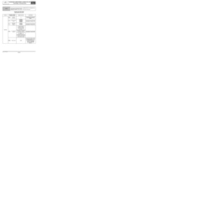 76
76 77
77 78
78 79
79 80
80 81
81 82
82 83
83 84
84 85
85 86
86 87
87 88
88 89
89 90
90 91
91 92
92 93
93 94
94 95
95 96
96 97
97 98
98 99
99 100
100 101
101 102
102 103
103 104
104 105
105 106
106 107
107 108
108 109
109 110
110 111
111 112
112 113
113 114
114 115
115 116
116 117
117 118
118 119
119 120
120 121
121 122
122 123
123 124
124 125
125 126
126 127
127 128
128 129
129 130
130 131
131 132
132 133
133 134
134 135
135 136
136 137
137 138
138 139
139 140
140 141
141 142
142 143
143 144
144 145
145 146
146 147
147 148
148 149
149 150
150 151
151 152
152 153
153 154
154 155
155 156
156 157
157 158
158 159
159 160
160 161
161 162
162 163
163 164
164 165
165 166
166 167
167 168
168 169
169 170
170 171
171 172
172 173
173 174
174 175
175 176
176 177
177 178
178