Page 1355 of 4331
DI
N
O P
Check voltage between key switch and ignition knob switch harness
connector and ground.
OK or NG OK >> Replace BCM. Refer to
BCS-18, " Removal and Installa-
tion of BCM " .
NG >> Repair harness or connector.
Lighting Switch Signal Inspection INFOID:0000000004307037OK >> Lighting switch signal is OK. Return to
DI-47, " Trouble Diagnosis " .
NG >> Check the lighting switch. Refer to LT-63, " Combination Switch Inspection " .
Parking Brake Switch Signal Inspection INFOID:0000000004307038OK >> Replace combination meter. Refer to
DI-19, " Removal and Installation " .
NG >> GO TO 2. B
Page 1453 of 4331

EC
NP
O
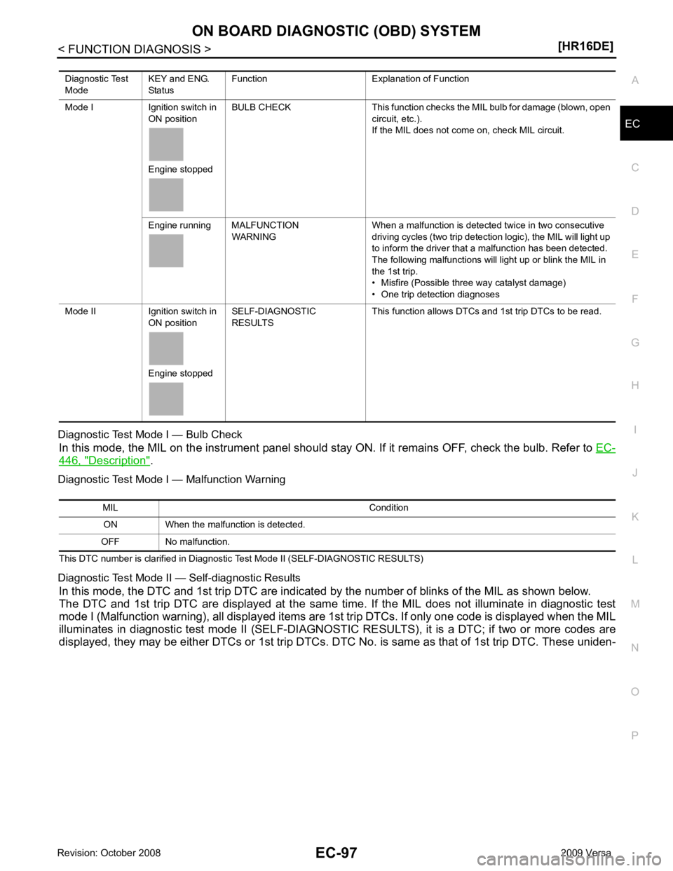
Diagnostic Test Mode I — Bulb Check
In this mode, the MIL on the instrument panel should st ay ON. If it remains OFF, check the bulb. Refer to EC-446, " Description " .
Diagnostic Test Mode I — Malfunction Warning
This DTC number is clarified in Diagnostic Test Mode II (SELF-DIAGNOSTIC RESULTS)
Diagnostic Test Mode II — Self-diagnostic Results In this mode, the DTC and 1st trip DTC are indicated by the number of blinks of the MIL as shown below.
The DTC and 1st trip DTC are displayed at the same time. If the MIL does not illuminate in diagnostic test
mode I (Malfunction warning), all displa yed items are 1st trip DTCs. If only one code is displayed when the MIL
illuminates in diagnostic test mode II (SELF-DIAGNOSTIC RESULTS), it is a DTC; if two or more codes are
displayed, they may be either DTCs or 1st trip DTCs. DTC No. is same as that of 1st trip DTC. These uniden-
Diagnostic Test
Mode KEY and ENG.
Status Function Explanation of Function
Mode I Ignition switch in ON position
Engine stopped BULB CHECK This function checks the MIL bulb for damage (blown, open
circuit, etc.).
If the MIL does not come on, check MIL circuit.
Engine running MALFUNCTION WARNING When a malfunction is detected twice in two consecutive
driving cycles (two trip detection logic), the MIL will light up
to inform the driver that a malfunction has been detected.
The following malfunctions will light up or blink the MIL in
the 1st trip.
• Misfire (Possible three way catalyst damage)
• One trip detection diagnoses
Mode II Ignition switch in ON position
Engine stopped SELF-DIAGNOSTIC
RESULTS This function allows DTCs and 1st trip DTCs to be read.
Page 1833 of 4331

EC
NP
O
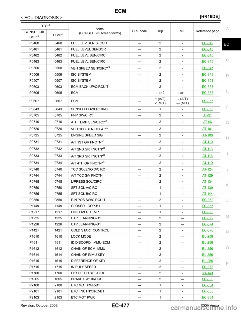
P0460 0460 FUEL LEV SEN SLOSH — 2
×EC-342 P0461 0461 FUEL LEVEL SENSOR — 2
×EC-343 P0462 0462 FUEL LEVL SEN/CIRC — 2
×EC-345 P0463 0463 FUEL LEVL SEN/CIRC — 2
×EC-345 P0500 0500
VEH SPEED SEN/CIRC*5
— 2 ×EC-347 P0506 0506 ISC SYSTEM — 2
×EC-349 P0507 0507 ISC SYSTEM — 2
×EC-351 P0603 0603 ECM BACK UP/CIRCUIT — 2
×EC-353 P0605 0605 ECM — 1 or 2
× or — EC-355 P0607 0607 ECM —
1 (A/T)
2 (M/T) ×
(A/T)
— (M/T) EC-357 P0643 0643 SENSOR POWER/CIRC — 1
×EC-358 P0705 0705 PNP SW/CIRC — 2
×AT-91 P0710 0710
ATF TEMP SEN/CIRC*8
— 2 ×AT-96 P0720 0720
VEH SPD SEN/CIR AT*5
— 2 ×AT-101 P0725 0725 ENGINE SPEED SIG — 2
×AT-106 P0731 0731
A/T 1ST GR FNCTN*8
— 2 ×AT-110 P0732 0732
A/T 2ND GR FNCTN*8
— 2 ×AT-113 P0733 0733
A/T 3RD GR FNCTN*8
— 2 ×AT-116 P0734 0734
A/T 4TH GR FNCTN*8
— 2 ×AT-119 P0740 0740 TCC SOLENOID/CIRC — 2
×AT-124 P0744 0744 A/T TCC S/V FNCTN — 2
×AT-129 P0745 0745 L/PRESS SOL/CIRC — 2
×AT-134 P0750 0750 SFT SOL A/CIRC — 1
×AT-139 P0755 0755 SFT SOL B/CIRC — 1
×AT-144 P0850 0850 P-N POS SW/CIRCUIT — 2
×EC-362 P1148 1148 CLOSED LOOP-B1 — 1
×EC-367 P1217 1217 ENG OVER TEMP — 1
×EC-368 P1225 1225 CTP LEARNING-B1 — 2 —
EC-372P1226 1226 CTP LEARNING-B1 — 2 —
EC-374P1421 1421 COLD START CONTROL — 2
×EC-376 P1610 1610 LOCK MODE — 2 —
BL-259P1611 1611 ID DISCORD, IMMU-ECM — 2 —
BL-259P1612 1612 CHAIN OF ECM-IMMU — 2 —
BL-259P1614 1614 CHAIN OF IMMU-KEY — 2 —
BL-259P1615 1615 DIFFERENCE OF KEY — 2 —
BL-259P1715 1715 IN PULY SPEED — 2 —
EC-378P1760 1760 O/R CLTCH SOL/CIRC — 2
×AT-149 P1805 1805 BRAKE SW/CIRCUIT — 2 —
EC-380P2100 2100 ETC MOT PWR-B1 — 1
×EC-384 P2101 2101 ETC FNCTN/CIRC-B1 — 1
×EC-388 P2103 2103 ETC MOT PWR — 1
×EC-384 DTC*
1
Items
(CONSULT-III screen terms) SRT code Trip MIL Reference page
CONSULT-III
GST* 2
ECM*3
Page 1866 of 4331
P1574 1574 ASCD VHL SPD SEN
EC-916DTC*1
Items
(CONSULT-III screen terms) Reference page
CONSULT-III
GST* 2
ECM*3 P1611 1611 ID DISCORD,IMMU-ECM
BL-259P1612 1612 CHAIN OF ECM-IMMU
BL-259P1614 1614 CHAIN OF IMMU-KEY
BL-259P1615 1615 DIFFERENCE OF KEY
BL-259DTC*1
Items
(CONSULT-III screen terms) Reference page
CONSULT-III
GST* 2
ECM*3
P1705 1705 TP SEN/CIRC CVT CVT-299P1715 1715 IN PULY SPEED
EC-918 (A/T),
EC-919 (CVT)
P1740 1740 LU-SLCT SOL/CIRC CVT-306P1760 1760 O/R CLTCH SOL/CIRC
AT-149P1777 1777 STEP MOTR CIRC
CVT-311P1778 1778 STEP MOTR FNC
CVT-315P1805 1805 BRAKE SW/CIRCUIT
EC-921DTC*1
Items
(CONSULT-III screen terms) Reference page
CONSULT-III
GST* 2
ECM*3
P2100 2100 ETC MOT PWR-B1 EC-925P2101 2101 ETC FNCTN/CIRC-B1
EC-929P2103 2103 ETC MOT PWR
EC-925
Page 1900 of 4331

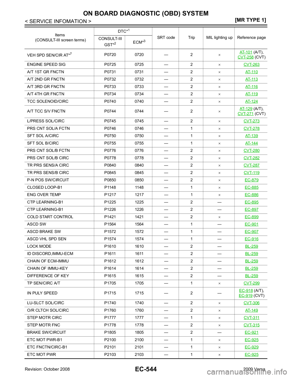
(A/T),
CVT-258 (CVT)
ENGINE SPEED SIG P0725 0725 — 2 ×CVT-263 A/T 1ST GR FNCTN P0731 0731 — 2
×AT-110 A/T 2ND GR FNCTN P0732 0732 — 2
×AT-113 A/T 3RD GR FNCTN P0733 0733 — 2
×AT-116 A/T 4TH GR FNCTN P0734 0734 — 2
×AT-119 TCC SOLENOID/CIRC P0740 0740 — 2
×AT-124 A/T TCC S/V FNCTN P0744 0744 — 2
×AT-129 (A/T),
CVT-271 (CVT)
L/PRESS SOL/CIRC P0745 0745 — 2 ×CVT-273 PRS CNT SOL/A FCTN P0746 0746 — 1
×CVT-278 SFT SOL A/CIRC P0750 0750 — 1
×AT-139 SFT SOL B/CIRC P0755 0755 — 1
×AT-144 PRS CNT SOL/B FCTN P0776 0776 — 2
×CVT-280 PRS CNT SOL/B CIRC P0778 0778 — 2
×CVT-282 TR PRS SENS/A CIRC P0840 0840 — 2
×CVT-287 TR PRS SENS/B CIRC P0845 0845 — 2
×CVT-119 P-N POS SW/CIRCUIT P0850 0850 — 2
×EC-879 CLOSED LOOP-B1 P1148 1148 — 1
×EC-885 ENG OVER TEMP P1217 1217 — 1
×EC-886 CTP LEARNING-B1 P1225 1225 — 2 —
EC-895CTP LEARNING-B1 P1226 1226 — 2 —
EC-897COLD START CONTROL P1421 1421 — 2
×EC-899 ASCD SW P1564 1564 — 1 —
EC-901ASCD BRAKE SW P1572 1572 — 1 —
EC-907ASCD VHL SPD SEN P1574 1574 — 1 —
EC-916LOCK MODE P1610 1610 — 2 —
BL-259ID DISCORD,IMMU-ECM P1611 1611 — 2 —
BL-259CHAIN OF ECM-IMMU P1612 1612 — 2 —
BL-259CHAIN OF IMMU-KEY P1614 1614 — 2 —
BL-259DIFFERENCE OF KEY P1615 1615 — 2 —
BL-259TP SEN/CIRC A/T P1705 1705 — 1
×CVT-299 IN PULY SPEED P1715 1715 — 2 —
EC-918 (A/T),
EC-919 (CVT)
LU-SLCT SOL/CIRC P1740 1740 — 2 ×CVT-306 O/R CLTCH SOL/CIRC P1760 1760 — 2
×AT-149 STEP MOTR CIRC P1777 1777 — 1
×CVT-311 STEP MOTR FNC P1778 1778 — 2
×CVT-315 BRAKE SW/CIRCUIT P1805 1805 — 2 —
EC-921ETC MOT PWR-B1 P2100 2100 — 1
×EC-925 ETC FNCTN/CIRC-B1 P2101 2101 — 1
×EC-929 ETC MOT PWR P2103 2103 — 1
×EC-925 Items
(CONSULT-III screen terms) DTC*
1
SRT code Trip MIL lighting up Reference page
CONSULT-III
GST* 2
ECM*3
Page 1914 of 4331

Emission-
related Diagnostic Information " .
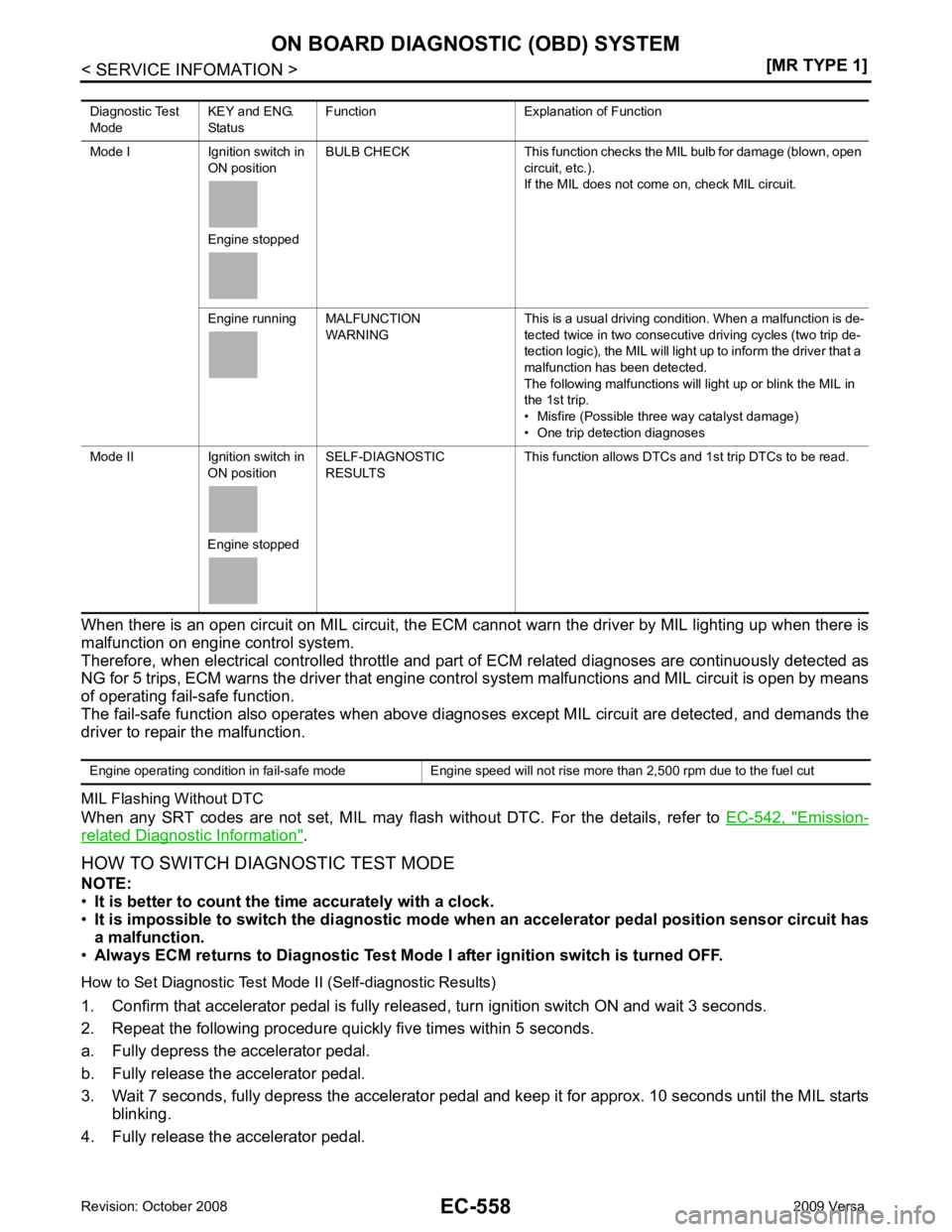
HOW TO SWITCH DIAGNOSTIC TEST MODE
NOTE:
• It is better to count the ti me accurately with a clock.
• It is impossible to switch the di agnostic mode when an accelerator pedal position sensor circuit has
a malfunction.
• Always ECM returns to Diagnostic Test Mode I after ignition switch is turned OFF.
How to Set Diagnostic Test Mode II (Self-diagnostic Results)
1. Confirm that accelerator pedal is fully releas ed, turn ignition switch ON and wait 3 seconds.
2. Repeat the following procedure quickly five times within 5 seconds.
a. Fully depress the accelerator pedal.
b. Fully release the accelerator pedal.
3. Wait 7 seconds, fully depress the accelerator pedal and keep it for approx. 10 seconds until the MIL starts blinking.
4. Fully release the accelerator pedal. Diagnostic Test
Mode KEY and ENG.
Status Function Explanation of Function
Mode I Ignition switch in ON position
Engine stopped BULB CHECK This function checks the MIL bulb for damage (blown, open
circuit, etc.).
If the MIL does not come on, check MIL circuit.
Engine running MALFUNCTION WARNING This is a usual driving condition. When a malfunction is de-
tected twice in two consecutive driving cycles (two trip de-
tection logic), the MIL will light up to inform the driver that a
malfunction has been detected.
The following malfunctions will light up or blink the MIL in
the 1st trip.
• Misfire (Possible three way catalyst damage)
• One trip detection diagnoses
Mode II Ignition switch in ON position
Engine stopped SELF-DIAGNOSTIC
RESULTS This function allows DTCs an
d 1st trip DTCs to be read.
Page 1927 of 4331
EC
NP
O
• : Vehicle front
2. Connect No. 4 ignition coil (1) and No. 4 spark plug with suitable high-tension wire (A) as shown, and attach timing light clamp (B) to this wire.
• : Vehicle front
3. Check ignition timing. • Timing indicator (1)
Procedure After Replacing ECM INFOID:0000000004537045
When replacing ECM, the following procedure must be performed.
1. Perform initialization of NVIS (NATS) system and registration of all NVIS (NATS) ignition key IDs.
Refer to BL-249, " ECM Re-communicating Function " .
2. Perform EC-572, " VIN Registration " .
3. Perform EC-572, " Accelerator Pedal Released Position Learning " .
4. Perform EC-572, " Throttle Valve Closed Position Learning " . PBIB3322E
PBIB3263E
Page 2227 of 4331
EC
NP
O
2. Replace ECM.
3. Perform initialization of NVIS (NATS) system and registration of all NVIS (NATS) ignition key IDs.
Refer to BL-249, " ECM Re-communicating Function " .
4. Perform EC-572, " VIN Registration " .
5. Perform EC-572, " Accelerator Pedal Released Position Learning " .
6. Perform EC-572, " Throttle Valve Closed Position Learning " .
7. Perform EC-572, " Idle Air Volume Learning " .
>> INSPECTION END