2009 NISSAN TIIDA key
[x] Cancel search: keyPage 1303 of 4331

DI
N
O P
CONTENTS
DRIVER INFORMATION SYSTEM
SERVICE INFORMATION .. ..........................2
PRECAUTION ................................................ .....2
Precaution for Supplemental Restraint System
(SRS) "AIR BAG" and "SEAT BELT PRE-TEN-
SIONER" ............................................................. ......
2
COMBINATION METERS .............................. .....3
Component Parts and Harness Connector Loca-
tion ...................................................................... ......
3
System Description ............................................. ......3
Arrangement of Combination Meter .................... ......5
Internal Circuit ..................................................... ......6
Wiring Diagram - METER - ................................. ......7
Combination Meter Harness Connector Terminal
Layout ................................................................. ......
9
Terminal and Reference Value for Combination
Meter ................................................................... ......
9
Self-Diagnosis Mode of Combination Meter ........ ....10
CONSULT-III Function (METER/M&A) ............... ....12
Trouble Diagnosis ............................................... ....13
Symptom Chart ................................................... ....14
Power Supply and Ground Circuit Inspection ..... ....14
Vehicle Speed Signal Inspection ......................... ....15
Engine Speed Signal Inspection ......................... ....16
Fuel Level Sensor Signal Inspection ................... ....16
Fuel Gauge Fluctuates, Indicates Wrong Value, or
Varies .................................................................. ....
18
Fuel Gauge Does Not Move to Full-position ...........18
DTC [U1000] CAN Communication Circuit ......... ....18
Electrical Component Inspection ......................... ....19
Removal and Installation .........................................19
WARNING LAMPS ......................................... ....20
Schematic ........................................................... ....20
Wiring Diagram - WARN - ................................... ....21 Oil Pressure Wa
rning Lamp Stays Off (Ignition
Switch ON) .......................................................... ....
29
Oil Pressure Wa rning Lamp Does Not Turn Off
(Oil Pressure Is Normal) ...................................... ....
31
Component Inspection ......................................... ....31
A/T INDICATOR ................................................ 33
System Description .............................................. ....33
Wiring Diagram - AT/IND - ................................... ....34
A/T Indicator Does Not Illuminate ........................ ....35
CVT INDICATOR ............................................... 37
System Description .............................................. ....37
Schematic ............................................................ ....37
Wiring Diagram - CVTIND - ................................. ....38
CVT Indicator Does Not Illuminate ...................... ....40
WARNING CHIME ............................................. 42
Component Parts and Harness Connector Loca-
tion ....................................................................... ....
42
System Description .............................................. ....42
Wiring Diagram - CHIME - ................................... ....45
Terminal and Reference Value for BCM ..................46
CONSULT-III Function (B CM) .................................46
Trouble Diagnosis ................................................ ....47
Combination Meter Buzzer Cir cuit Inspection .........48
Front Door Switch LH Signal Inspection .............. ....49
Key Switch Signal Inspec tion (Without Intelligent
Key) ..................................................................... ....
50
Key Switch and Ignition Knob Switch Signal In-
spection (With Intelligent Key, When Mechanical
Key Is Used) ........................................................ ....
51
Lighting Switch Signal Inspection ........................ ....53
Parking Brake Switch Signal Inspection .............. ....53
Electrical Component Inspection ......................... ....54
Page 1315 of 4331

DI
N
O P
NOTE:
Some items are not available due to vehicle specification.
*: The monitor will indicate “OFF” even though the brake warnin g lamp is on if either of the following conditions exist.
• The parking brake is engaged
• The brake fluid level is low
Trouble Diagnosis INFOID:0000000004307005
HOW TO PERFORM TROUBLE DIAGNOSIS 1. Confirm the symptom or customer complaint.
2. Perform preliminary check. Refer to "PRELIMINARY CHECK" .
3. According to the symptom chart, repair or replace the cause of the malfunction. Refer to DI-14, " Symptom
Chart " .
4. Does the meter operate normally? If so, GO TO 5. If not, GO TO 2.
5. Inspection End.
PRELIMINARY CHECK Self-Diagnosis Mode of Combination Meter " .
Does self - diagnosis mode operate?
YES >> GO TO 2.
TURN IND [ON/OFF] X Indicates [ON/O
FF] condition of turn indicator.
OIL W/L [ON/OFF] X Indicates [ON/OFF] condition of oil pressure warning lamp.
ABS W/L [ON/OFF] X Indicates [ON/O FF] condition of ABS warning lamp.
BRAKE W/L [ON/OFF] X Indicates [ON/OFF] condition of brake warning lamp.*
KEY G W/L [ON/OFF] X Indicates [ON/OFF] condition of KEY warning lamp (green).
KEY R W/L [ON/OFF] X Indicates [ON/OFF] condition of KEY warning lamp (red).
KEY KNOB W/L [ON/OFF] X Indicates [ON/OFF] condition of LOCK warning lamp.
PNP P SW [ON/OFF] X X Indicates [ON/OFF] condition of inhibitor P switch.
PNP N SW [ON/OFF] X X Indicates [ON/OFF] condition of inhibitor N switch.
O/D OFF SW [ON/OFF] X Indicates [ON/ OFF] condition of O/D OFF switch.
BRAKE SW [ON/OFF] X Indicates [ON/OFF] condition of parking brake switch.
P RANGE IND [ON/OFF] X X Indicates [ON/OFF] condition of A/T or CVT shift P range indi-
cator.
R RANGE IND [ON/OFF] X X Indicates [ON/OFF] condition of A/T or CVT shift R range indi-
cator.
N RANGE IND [ON/OFF] X X Indicates [ON/OFF] condition of A/T or CVT shift N range indi-
cator.
D RANGE IND [ON/OFF] X X Indicates [ON/OFF] condition of A/T or CVT shift D range indi-
cator.
2 RANGE IND [ON/OFF] X X Indicates [ON/OFF] condition of A/T shift 2 range indicator.
L RANGE IND [ON/OFF] X X Indicates [ON/OFF] condition of CVT shift L range indicator.
1 RANGE IND [ON/OFF] X X Indicates [ON/OFF] condition of A/T shift 1 range indicator.
CRUISE IND [ON/OFF] X Indicates [ON/O FF] condition of CRUISE indicator.
SET IND [ON/OFF] X Indicates [ON/OFF] condition of SET indicator.
O/D OFF W/L [ON/OFF] X Indicates [ON/OFF] condition of O/D OFF indicator lamp.
e-4WD W/L [ON/OFF] X This item is not used for this model. “OFF” is always displayed.
EPS W/L [ON/OFF] X Indicates [ON/O FF] condition of EPS warning lamp.
Display item [Unit]
MAIN
SIGNALS SELECTION
FROM MENU Contents
Page 1345 of 4331
![NISSAN TIIDA 2009 Service Repair Manual DI
N
O P
• through 10A fuse [No. 8, located in the fuse block (J/B)]
• to BCM terminal 57,
• through 10A fuse [No. 13, located in the fuse block (J/B)]
• to combination meter terminal 27.
Wit NISSAN TIIDA 2009 Service Repair Manual DI
N
O P
• through 10A fuse [No. 8, located in the fuse block (J/B)]
• to BCM terminal 57,
• through 10A fuse [No. 13, located in the fuse block (J/B)]
• to combination meter terminal 27.
Wit](/manual-img/5/57398/w960_57398-1344.png)
DI
N
O P
• through 10A fuse [No. 8, located in the fuse block (J/B)]
• to BCM terminal 57,
• through 10A fuse [No. 13, located in the fuse block (J/B)]
• to combination meter terminal 27.
With ignition switch in the ON or START position, power is supplied
• through 10A fuse [No. 6, located in the fuse block (J/B)]
• to BCM terminal 38,
• through 10A fuse [No. 3, located in the fuse block (J/B)]
• to combination meter terminal 28.
Ground is supplied
• to BCM terminal 67 and
• to combination meter terminals 21, 22 and 23
• through grounds M57 and M61.
IGNITION KEY WARNING CHIME (WITHOUT INTELLIGENT KEY) With the key inserted into the key switch, and the igni tion switch in the OFF or ACC position, when driver's
door is opened, the warning chime will sound.
• BCM detects key inserted into the ignition switch, and sends key warning signal to combination meter with CAN communication line.
• When combination meter receives key warning signal, it sounds warning chime.
IGNITION KEY WARNING CHIME (WITH INTELLIGENT KEY)
When Mechanical Key Is Used With the key inserted into the key switch, and the igniti on switch in the LOCK or ACC position, when driver's
door is opened, the warning chime will sound.
• BCM detects key inserted into the ignition switch, and sends key warning signal to combination meter with CAN communication line.
• When combination meter receives key warning signal, it sounds warning chime.
When Intelligent Key Is Carried With The Driver
Refer to BL-88, " System Description " .
LIGHT WARNING CHIME The warning chime sounds, when driver's door is opened (door switch ON) with lighting switch ON and the
ignition switch is in any position other than ON or START.
NOTE:
BCM detected lighting switch in the 1st or 2nd position, refer to LT-62, " Combination Switch Reading Func-
tion " .
• BCM detects headlamps are illuminated, and sends li ght warning signal to combination meter with CAN
communication lines. WKIA5464E
Page 1349 of 4331
![NISSAN TIIDA 2009 Service Repair Manual DI
N
O P
DATA MONITOR
Display Item List
ACTIVE TEST
Display Item List
SELF-DIAG RESULTS
Display Item List
NOTE:
If “CAN communication [U1000]” is indicated, after prin ting the monitor i NISSAN TIIDA 2009 Service Repair Manual DI
N
O P
DATA MONITOR
Display Item List
ACTIVE TEST
Display Item List
SELF-DIAG RESULTS
Display Item List
NOTE:
If “CAN communication [U1000]” is indicated, after prin ting the monitor i](/manual-img/5/57398/w960_57398-1348.png)
DI
N
O P
DATA MONITOR
Display Item List
ACTIVE TEST
Display Item List
SELF-DIAG RESULTS
Display Item List
NOTE:
If “CAN communication [U1000]” is indicated, after prin ting the monitor item, go to “LAN system”. Refer to
LAN-17, " Trouble Diagnosis Flow Chart " .
Trouble Diagnosis INFOID:0000000004307032
HOW TO PERFORM TROUBLE DIAGNOSIS 1. Confirm the symptom and customer complaint.
2. Understand the outline of system. Refer to DI-42, " System Description " .
3. Perform the preliminary inspection. Refer to "PRELIMINARY INSPECTION".
4. According to symptom c hart, repair or replace the cause of the malfunction. Refer to "SYMPTOM
CHART".
5. Does warning chime system operate normally? If it operates normally, GO TO 6. If not, GO TO 4.
6. Inspection End.
PRELIMINARY INSPECTION BCM diagnostic
test item Diagnostic mode Description
Inspection by part WORK SUPPORT
Supports inspections and adjustments. Commands are transmitted to the BCM for
setting the status suitable for required operation, input/output signals are received
from the BCM and received data is displayed.
DATA MONITOR Displays BCM input/output data in real time. ACTIVE TEST Operation of electrical loads can be checked by sending drive signal to them.
SELF-DIAG RESULTS Displays BCM self-diagnosis results.
CAN DIAG SUPPORT MNTR The result of transmit/receive diagnosis of CAN communication can be read. ECU PART NUMBER BCM part number can be read.CONFIGURATION Performs BCM configuration read/write functions. Monitored item ALL SIGNALS
SELECTION
FROM MENU Contents
IGN ON SW X X Indicates [ON/OFF] condition of ignition switch.
KEY ON SW X X Indicates [ON/OFF] condition of key switch.
DOOR SW-DR X X Indicates [ON/OFF] condition of front door switch LH.
LIGHT SW 1ST X X Indicates [ON/OFF] condition of lighting switch.
BUCKLE SW X X Indicates [ON/OFF] condition of seat belt buckle switch LH. Test item Malfunction is detected when···
IGN KEY WARN ALM This test is able to check key warning chime operation.
LIGHT WARN ALM This test is able to check light warning chime operation.
SEAT BELT WARN TEST This test is able to check seat belt warning chime operation. Display item [Code] Malfunction is detected when...
CAN communication [U1000] Malfunction is detected in CAN communication.
Page 1350 of 4331

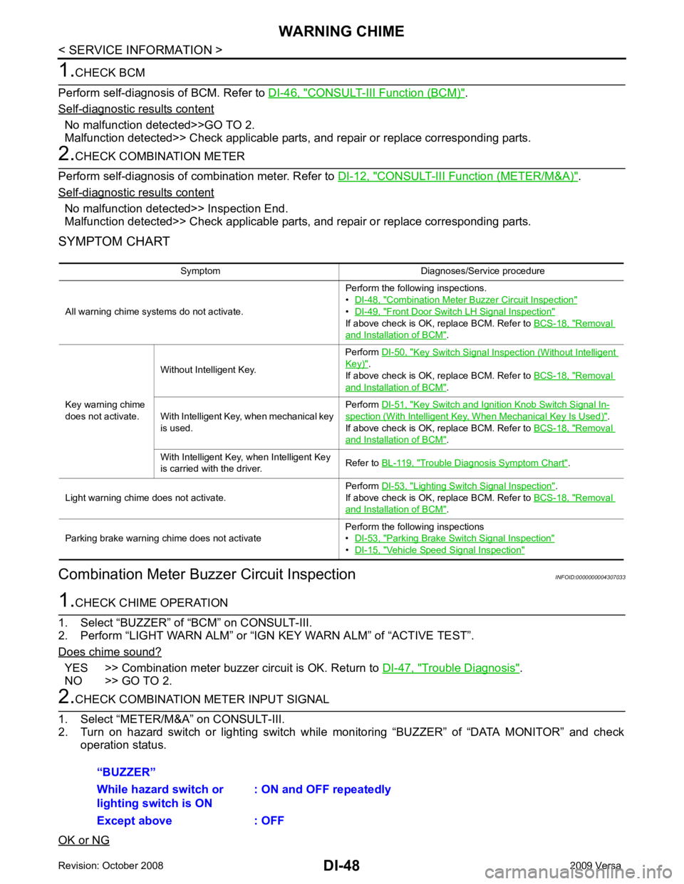
CONSULT-III Function (BCM) " .
Self - diagnostic results content
No malfunction detected>>GO TO 2.
Malfunction detected>> Check applicable parts, and repair or replace corresponding parts. CONSULT-III Function (METER/M&A) " .
Self - diagnostic results content
No malfunction detected>> Inspection End.
Malfunction detected>> Check applicable parts, and repair or replace corresponding parts.
SYMPTOM CHART
Combination Meter Buzzer Circuit Inspection INFOID:0000000004307033YES >> Combination meter buzzer circuit is OK. Return to
DI-47, " Trouble Diagnosis " .
NO >> GO TO 2. Combination Meter Buzzer Circuit Inspection "
•
DI-49, " Front Door Switch LH Signal Inspection "
If above check is OK, replace BCM. Refer to
BCS-18, " Removal
and Installation of BCM " .
Key warning chime
does not activate. Without Intelligent Key.
Perform
DI-50, " Key Switch Signal Inspection (Without Intelligent
Key) " .
If above check is OK, replace BCM. Refer to BCS-18, " Removal
and Installation of BCM " .
With Intelligent Key, when mechanical key
is used. Perform
DI-51, " Key Switch and Ignition Knob Switch Signal In-
spection (With Intelligent Key, When Mechanical Key Is Used) " .
If above check is OK, replace BCM. Refer to BCS-18, " Removal
and Installation of BCM " .
With Intelligent Key, when Intelligent Key
is carried with the driver. Refer to
BL-119, " Trouble Diagnosis Symptom Chart " .
Light warning chime does not activate. Perform
DI-53, " Lighting Switch Signal Inspection " .
If above check is OK, replace BCM. Refer to BCS-18, " Removal
and Installation of BCM " .
Parking brake warning chime does not activate Perform the following inspections
• DI-53, " Parking Brake Switch Signal Inspection "
•
DI-15, " Vehicle Speed Signal Inspection "
Page 1352 of 4331

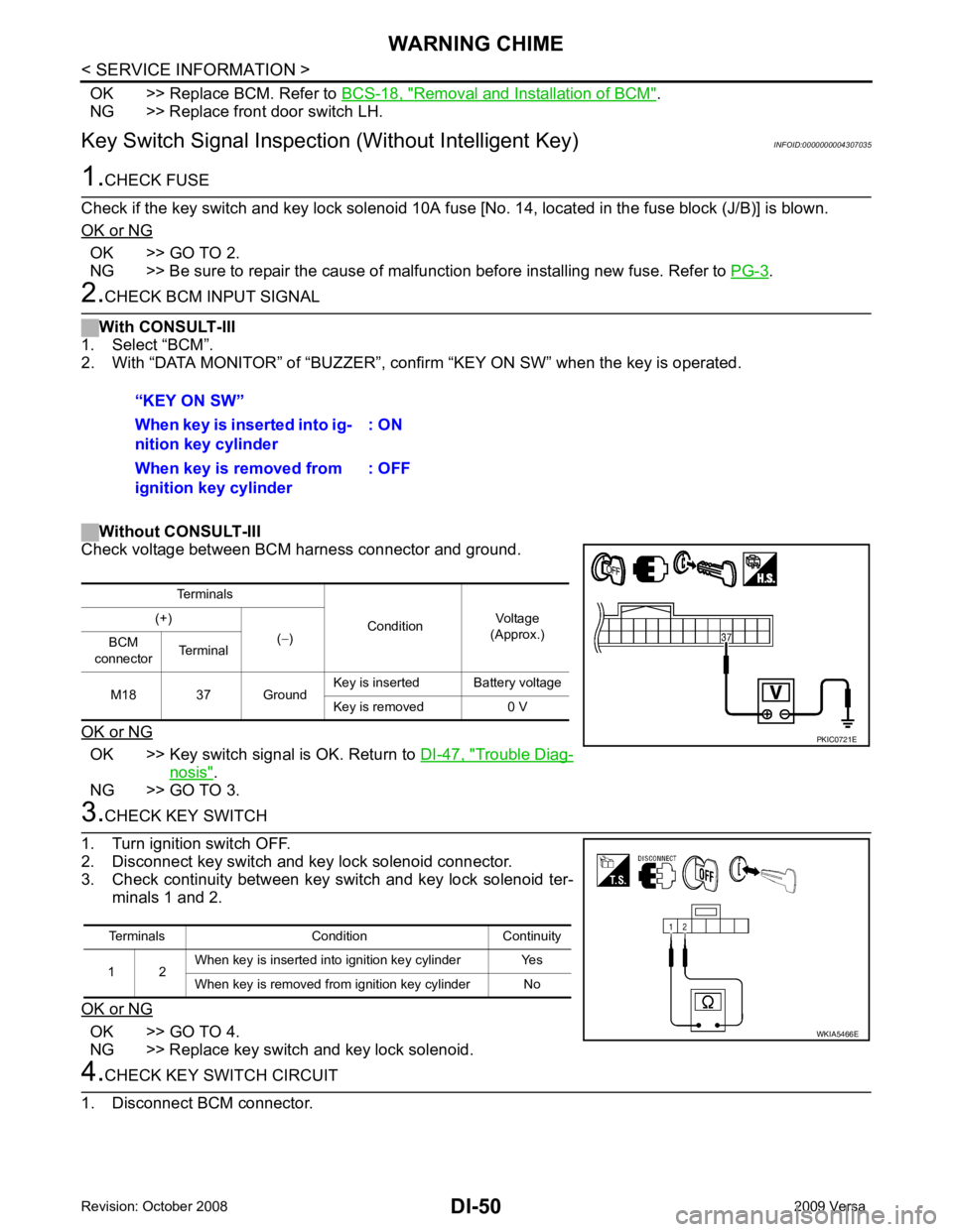
Removal and Installation of BCM " .
NG >> Replace front door switch LH.
Key Switch Signal Inspection (Without Intelligent Key) INFOID:0000000004307035OK >> GO TO 2.
NG >> Be sure to repair the cause of malfunction before installing new fuse. Refer to PG-3 .
OK >> Key switch signal is OK. Return to
DI-47, " Trouble Diag-
nosis " .
NG >> GO TO 3. OK >> GO TO 4.
NG >> Replace key switch and key lock solenoid.
Page 1353 of 4331

DI
N
O P
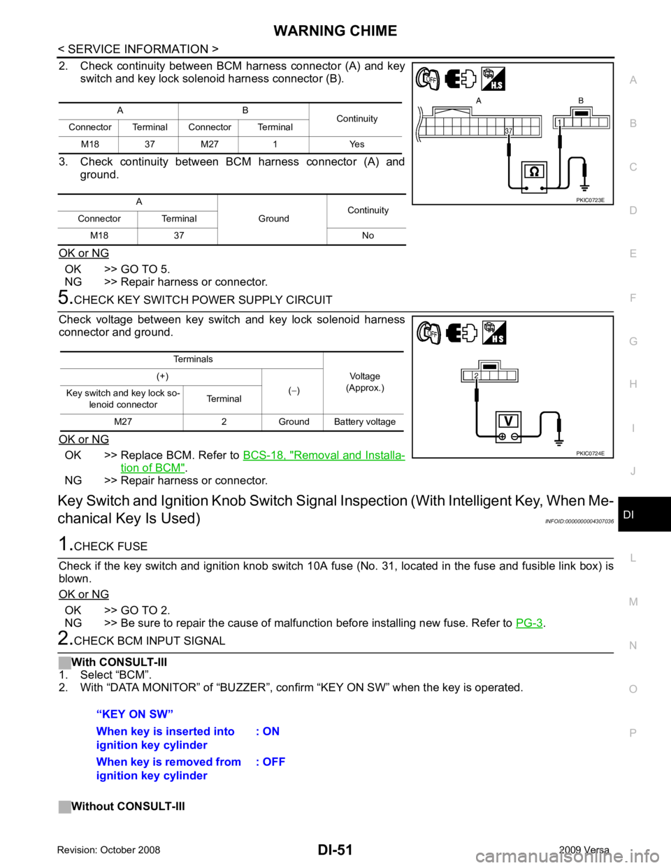
2. Check continuity between BCM harness connector (A) and key
switch and key lock solenoid harness connector (B).
3. Check continuity between BCM harness connector (A) and ground.
OK or NG OK >> GO TO 5.
NG >> Repair harness or connector. OK >> Replace BCM. Refer to
BCS-18, " Removal and Installa-
tion of BCM " .
NG >> Repair harness or connector.
Key Switch and Ignition Knob Switch Signal Inspection (With Intelligent Key, When Me-
chanical Key Is Used) INFOID:0000000004307036OK >> GO TO 2.
NG >> Be sure to repair the cause of malfunction before installing new fuse. Refer to PG-3 .
Page 1354 of 4331

DI-52< SERVICE INFORMATION >
WARNING CHIME
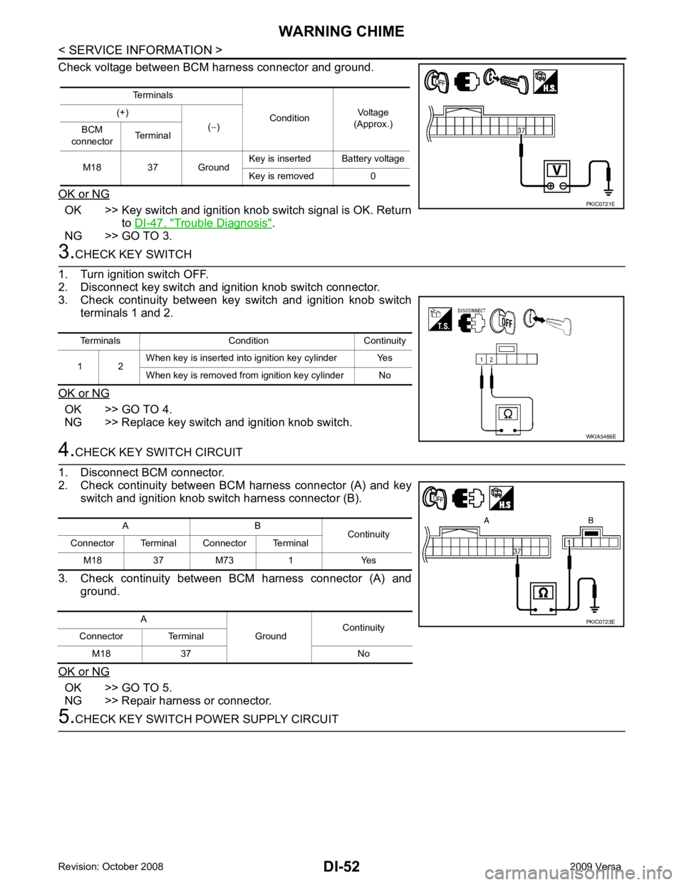
Check voltage between BCM harness connector and ground.
OK or NG OK >> Key switch and ignition knob switch signal is OK. Return
to DI-47, " Trouble Diagnosis " .
NG >> GO TO 3. 3.
CHECK KEY SWITCH
1. Turn ignition switch OFF.
2. Disconnect key switch and ignition knob switch connector.
3. Check continuity between key switch and ignition knob switch
terminals 1 and 2.
OK or NG OK >> GO TO 4.
NG >> Replace key switch and ignition knob switch. 4.
CHECK KEY SWITCH CIRCUIT
1. Disconnect BCM connector.
2. Check continuity between BCM harness connector (A) and key switch and ignition knob switch harness connector (B).
3. Check continuity between BCM harness connector (A) and ground.
OK or NG OK >> GO TO 5.
NG >> Repair harness or connector. 5.
CHECK KEY SWITCH PO WER SUPPLY CIRCUIT
Terminals
ConditionVoltage
(Approx.)
(+)
(− )
BCM
connector Terminal
M18 37 Ground Key is inserted Battery voltage
Key is removed 0 PKIC0721E
Terminals Condition Continuity
1 2 When key is inserted into ignition key cylinder Yes
When key is removed from ignition key cylinder No WKIA5466E
A B
Continuity
Connector Terminal Connector Terminal
M18 37 M73 1 Yes
A GroundContinuity
Connector Terminal
M18 37 No PKIC0723E