2009 NISSAN TIIDA key
[x] Cancel search: keyPage 2375 of 4331

EC
NP
O
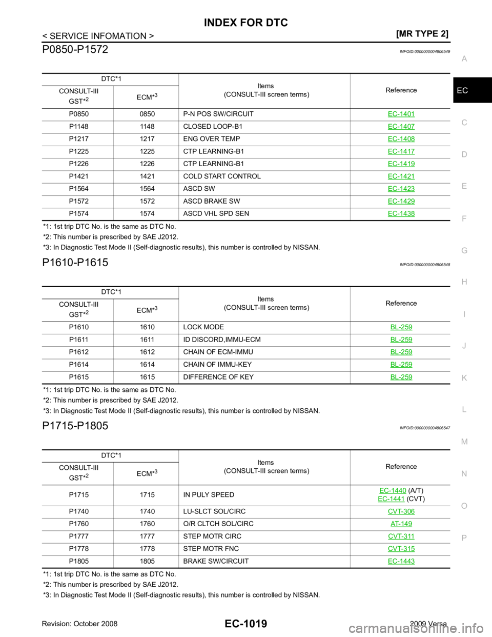
P0850-P1572
INFOID:0000000004806549
*1: 1st trip DTC No. is the same as DTC No.
*2: This number is prescribed by SAE J2012.
*3: In Diagnostic Test Mode II (Self-diagnostic results), this number is controlled by NISSAN.
P1610-P1615 INFOID:0000000004806548
*1: 1st trip DTC No. is the same as DTC No.
*2: This number is prescribed by SAE J2012.
*3: In Diagnostic Test Mode II (Self-diagnostic results), this number is controlled by NISSAN.
P1715-P1805 INFOID:0000000004806547
*1: 1st trip DTC No. is the same as DTC No.
*2: This number is prescribed by SAE J2012.
*3: In Diagnostic Test Mode II (Self-diagnostic results), this number is controlled by NISSAN.
DTC*1
Items
(CONSULT-III screen terms) Reference
CONSULT-III
GST* 2
ECM*3
P0850 0850 P-N POS SW/CIRCUIT EC-1401P1148 1148 CLOSED LOOP-B1
EC-1407P1217 1217 ENG OVER TEMP
EC-1408P1225 1225 CTP LEARNING-B1
EC-1417P1226 1226 CTP LEARNING-B1
EC-1419P1421 1421 COLD START CONTROL
EC-1421P1564 1564 ASCD SW
EC-1423P1572 1572 ASCD BRAKE SW
EC-1429P1574 1574 ASCD VHL SPD SEN
EC-1438DTC*1
Items
(CONSULT-III screen terms) Reference
CONSULT-III
GST* 2
ECM*3
P1610 1610 LOCK MODE BL-259P1611 1611 ID DISCORD,IMMU-ECM
BL-259P1612 1612 CHAIN OF ECM-IMMU
BL-259P1614 1614 CHAIN OF IMMU-KEY
BL-259P1615 1615 DIFFERENCE OF KEY
BL-259DTC*1
Items
(CONSULT-III screen terms) Reference
CONSULT-III
GST* 2
ECM*3
P1715 1715 IN PULY SPEED EC-1440 (A/T)
EC-1441 (CVT)
P1740 1740 LU-SLCT SOL/CIRC CVT-306P1760 1760 O/R CLTCH SOL/CIRC
AT-149P1777 1777 STEP MOTR CIRC
CVT-311P1778 1778 STEP MOTR FNC
CVT-315P1805 1805 BRAKE SW/CIRCUIT
EC-1443
Page 2410 of 4331

(A/T)
CVT-249 (CVT)
INPUT SPD SEN/CIRC P0715 0715 — 2 ×CVT-254 VEH SPD SEN/CIR AT*
7
P0720 0720 — 2 ×AT-101 (A/T)
CVT-258 (CVT)
ENGINE SPEED SIG P0725 0725 — 2 ×
(A/T)
— (CVT) AT-106 (A/T)
CVT-263 (CVT)
A/T 1ST GR FNCTN* 8
P0731 0731 — 2 ×AT-110 A/T 2ND GR FNCTN*
8
P0732 0732 — 2 ×AT-113 A/T 3RD GR FNCTN*
8
P0733 0733 — 2 ×AT-116 A/T 4TH GR FNCTN*
8
P0734 0734 — 2 ×AT-119 TCC SOLENOID/CIRC P0740 0740 — 2
×AT-124 (A/T)
CVT-266 (CVT)
A/T TCC S/V FNCTN P0744 0744 — 2 ×AT-129 (A/T)
CVT-271 (CVT)
L/PRESS SOL/CIRC P0745 0745 — 2 ×AT-134 (A/T)
CVT-273 (CVT)
PRS CNT SOL/A FCTN P0746 0746 — 1 ×CVT-278 SFT SOL A/CIRC P0750 0750 — 1
×AT-139 SFT SOL B/CIRC P0755 0755 — 1
×AT-144 PRS CNT SOL/B FCTN P0776 0776 — 2
×CVT-280 PRS CNT SOL/B CIRC P0778 0778 — 2
×CVT-282 TR PRS SENS/A CIRC P0840 0840 — 2
×CVT-287 P-N POS SW/CIRCUIT P0850 0850 — 2
×EC-1401 CLOSED LOOP-B1 P1148 1148 — 1
×EC-1407 ENG OVER TEMP P1217 1217 — 1
×EC-1408 CTP LEARNING-B1 P1225 1225 — 2 —
EC-1417CTP LEARNING-B1 P1226 1226 — 2 —
EC-1419COLD START CONTROL P1421 1421 — 2
×EC-1421 ASCD SW P1564 1564 — 1 —
EC-1423ASCD BRAKE SW P1572 1572 — 1 —
EC-1429ASCD VHL SPD SEN P1574 1574 — 1 —
EC-1438LOCK MODE P1610 1610 — 2 —
BL-259ID DISCORD,IMMU-ECM P1611 1611 — 2 —
BL-259CHAIN OF ECM-IMMU P1612 1612 — 2 —
BL-259CHAIN OF IMMU-KEY P1614 1614 — 2 —
BL-259DIFFERENCE OF KEY P1615 1615 — 2 —
BL-259IN PULY SPEED P1715 1715 — 2 —
EC-1440 (A/T)
EC-1441 (CVT)
LU-SLCT SOL/CIRC P1740 1740 — 2 ×CVT-306 O/R CLTCH SOL/CIRC P1760 1760 — 2
×AT-149 STEP MOTR CIRC P1777 1777 — 1
×CVT-311 STEP MOTR FNC P1778 1778 — 2
×CVT-315 BRAKE SW/CIRCUIT P1805 1805 — 2 —
EC-1443Items
(CONSULT-III screen terms) DTC*
1
SRT code Trip MIL lighting up Reference
CONSULT-III
GST* 2
ECM*3
Page 2426 of 4331

Emission-
related Diagnostic Information " .
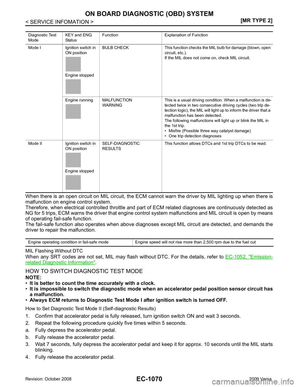
HOW TO SWITCH DIAGNOSTIC TEST MODE
NOTE:
• It is better to count the ti me accurately with a clock.
• It is impossible to switch the di agnostic mode when an accelerator pedal position sensor circuit has
a malfunction.
• Always ECM returns to Diagnostic Test Mode I after ignition switch is turned OFF.
How to Set Diagnostic Test Mode II (Self-diagnostic Results)
1. Confirm that accelerator pedal is fully releas ed, turn ignition switch ON and wait 3 seconds.
2. Repeat the following procedure quickly five times within 5 seconds.
a. Fully depress the accelerator pedal.
b. Fully release the accelerator pedal.
3. Wait 7 seconds, fully depress the accelerator pedal and keep it for approx. 10 seconds until the MIL starts blinking.
4. Fully release the accelerator pedal. Diagnostic Test
Mode KEY and ENG.
Status Function Explanation of Function
Mode I Ignition switch in ON position
Engine stopped BULB CHECK This function checks the MIL bulb for damage (blown, open
circuit, etc.).
If the MIL does not come on, check MIL circuit.
Engine running MALFUNCTION WARNING This is a usual driving condition. When a malfunction is de-
tected twice in two consecutive driving cycles (two trip de-
tection logic), the MIL will light up to inform the driver that a
malfunction has been detected.
The following malfunctions will light up or blink the MIL in
the 1st trip.
• Misfire (Possible three way catalyst damage)
• One trip detection diagnoses
Mode II Ignition switch in ON position
Engine stopped SELF-DIAGNOSTIC
RESULTS This function allows DTCs an
d 1st trip DTCs to be read.
Page 2436 of 4331
![NISSAN TIIDA 2009 Service Repair Manual EC-1080< SERVICE INFOMATION >
[MR TYPE 2]
BASIC SERVICE PROCEDURE
OK or NG OK >> GO TO 10.
NG >> GO TO 8. 8.
DETECT MALFUNCTIONING PART
Check the following.
• Check crankshaft position sensor (POS) NISSAN TIIDA 2009 Service Repair Manual EC-1080< SERVICE INFOMATION >
[MR TYPE 2]
BASIC SERVICE PROCEDURE
OK or NG OK >> GO TO 10.
NG >> GO TO 8. 8.
DETECT MALFUNCTIONING PART
Check the following.
• Check crankshaft position sensor (POS)](/manual-img/5/57398/w960_57398-2435.png)
EC-1080< SERVICE INFOMATION >
[MR TYPE 2]
BASIC SERVICE PROCEDURE
OK or NG OK >> GO TO 10.
NG >> GO TO 8. 8.
DETECT MALFUNCTIONING PART
Check the following.
• Check crankshaft position sensor (POS) and circuit.
Refer to EC-1293 .
• Check camshaft position sensor (PHASE) and circuit.
Refer to EC-1299 .
OK or NG OK >> GO TO 9.
NG >> 1. Repair or replace.
2. GO TO 4. 9.
CHECK ECM FUNCTION
1. Substitute another known-good ECM to check ECM f unction. (ECM may be the cause of an incident, but
this is a rare case.)
2. Perform initialization of NVIS (NATS) system and registration of all NVIS (NATS) ignition key IDs.
Refer to BL-249, " ECM Re-communicating Function " .
>> GO TO 4. 10.
CHECK IGNITION TIMING
1. Run engine at idle.
2. Check ignition timing with a timing light.
Refer to EC-1082, " Idle Speed and Ignition Timing Check " .
- Timing indicator (1)
OK or NG OK >> GO TO 19.
NG >> GO TO 11. 11.
PERFORM ACCELERATOR PEDAL RELEASED POSITION LEARNING
1. Stop engine.
2. Perform EC-1084, " Accelerator Pedal Released Position Learning " .
>> GO TO 12. 12.
PERFORM THROTTLE VALVE CL OSED POSITION LEARNING
Perform EC-1084, " Throttle Valve Closed Position Learning " .
>> GO TO 13. 13.
PERFORM IDLE AIR VOLUME LEARNING
Refer to EC-1084, " Idle Air Volume Learning " .
Is Idle Air Volume Lear ning carried out successfully?
Yes or No M/T: 700
± 50 rpm (in Neutral position)
A/T: 700 ± 50 rpm (in P or N position)
CVT: 700 ± 50 rpm (in P or N position)
M/T: 13 ± 5 ° BTDC (in Neutral position)
A/T: 13 ± 5 ° BTDC (in P or N position)
CVT: 13 ± 5 ° BTDC (in P or N position) PBIB3263E
Page 2438 of 4331
![NISSAN TIIDA 2009 Service Repair Manual EC-1082< SERVICE INFOMATION >
[MR TYPE 2]
BASIC SERVICE PROCEDURE
1. Substitute another known-good ECM to check ECM f unction. (ECM may be the cause of an incident, but
this is a rare case.)
2. Perfor NISSAN TIIDA 2009 Service Repair Manual EC-1082< SERVICE INFOMATION >
[MR TYPE 2]
BASIC SERVICE PROCEDURE
1. Substitute another known-good ECM to check ECM f unction. (ECM may be the cause of an incident, but
this is a rare case.)
2. Perfor](/manual-img/5/57398/w960_57398-2437.png)
EC-1082< SERVICE INFOMATION >
[MR TYPE 2]
BASIC SERVICE PROCEDURE
1. Substitute another known-good ECM to check ECM f unction. (ECM may be the cause of an incident, but
this is a rare case.)
2. Perform initialization of NVIS (NATS) system and registration of all NVIS (NATS) ignition key IDs.
Refer to BL-249, " ECM Re-communicating Function " .
>> GO TO 4. 19.
INSPECTION END
Did you replace ECM, referring this Basic Inspection procedure?
Yes or No Yes >> 1. Perform
EC-1084, " VIN Registration " .
2. INSPECTION END
No >> INSPECTION END
Idle Speed and Ignition Timing Check INFOID:0000000004499930
IDLE SPEED With CONSULT-III
Check idle speed in “DATA MONITOR” mode with CONSULT-III.
With GST
Check idle speed in Service $01 with GST.
IGNITION TIMING
Any of following two methods may be used.
Method A
1. Attach timing light to loop wire (1) as shown. • : Vehicle front
2. Check ignition timing. • Timing indicator (1)
Method B
1. Remove No. 4 ignition coil (1). PBIB3320E
PBIB3263E
Page 2439 of 4331
![NISSAN TIIDA 2009 Service Repair Manual BASIC SERVICE PROCEDURE
EC-1083
< SERVICE INFOMATION >
[MR TYPE 2] C
D E
F
G H
I
J
K L
M A EC
NP
O
• : Vehicle front
2. Connect No. 4 ignition coil (1) and No. 4 spark plug with suitable NISSAN TIIDA 2009 Service Repair Manual BASIC SERVICE PROCEDURE
EC-1083
< SERVICE INFOMATION >
[MR TYPE 2] C
D E
F
G H
I
J
K L
M A EC
NP
O
• : Vehicle front
2. Connect No. 4 ignition coil (1) and No. 4 spark plug with suitable](/manual-img/5/57398/w960_57398-2438.png)
BASIC SERVICE PROCEDURE
EC-1083
< SERVICE INFOMATION >
[MR TYPE 2] C
D E
F
G H
I
J
K L
M A EC
NP
O
• : Vehicle front
2. Connect No. 4 ignition coil (1) and No. 4 spark plug with suitable high-tension wire (A) as shown, and attach timing light clamp (B) to this wire.
• : Vehicle front
3. Check ignition timing. • Timing indicator (1)
Procedure After Replacing ECM INFOID:0000000004499931
When replacing ECM, the following procedure must be performed.
1. Perform initialization of NVIS (NATS) system and registration of all NVIS (NATS) ignition key IDs.
Refer to BL-249, " ECM Re-communicating Function " .
2. Perform EC-1084, " VIN Registration " .
3. Perform EC-1084, " Accelerator Pedal Released Position Learning " .
4. Perform EC-1084, " Throttle Valve Closed Position Learning " . PBIB3321E
PBIB3322E
PBIB3334E
PBIB3263E
Page 2894 of 4331

EI
N
O P
PRECAUTION
PRECAUTIONS
Precaution for Supplemental Restraint System (SRS) "AIR BAG" and "SEAT BELT
PRE-TENSIONER" INFOID:0000000004783758
The Supplemental Restraint System such as “A IR BAG” and “SEAT BELT PRE-TENSIONER”, used along
with a front seat belt, helps to reduce the risk or severi ty of injury to the driver and front passenger for certain
types of collision. This system includes seat belt switch inputs and dual stage front air bag modules. The SRS
system uses the seat belt switches to determine the front air bag deployment, and may only deploy one front
air bag, depending on the severity of a collision and w hether the front occupants are belted or unbelted.
Information necessary to service the system safely is included in the SRS and SB section of this Service Man-
ual.
WARNING:
• To avoid rendering the SRS inoper ative, which could increase the risk of personal injury or death in
the event of a collision which would result in air bag inflation, all maintenance must be performed by
an authorized NISSAN/INFINITI dealer.
• Improper maintenance, including in correct removal and installation of the SRS can lead to personal
injury caused by unintentional act ivation of the system. For removal of Spiral Cable and Air Bag
Module, see the SRS section.
• Do not use electrical test equipm ent on any circuit related to the SRS unless instructed to in this
Service Manual. SRS wiring harnesses can be identi fied by yellow and/or orange harnesses or har-
ness connectors.
• When working near the Airbag Diagnosis Sensor Un it or other Airbag System sensors with the Igni-
tion ON or engine running, DO NOT use air or el ectric power tools or strike near the sensor(s) with a
hammer. Heavy vibration could activate the sensor( s) and deploy the air bag(s), possibly causing
serious injury.
• When using air or electric power tools or hammers , always switch the Ignition OFF, disconnect the
battery, and wait at least 3 minutes before performing any service.
Precaution Necessary for Steering Wh eel Rotation After Battery Disconnect
INFOID:0000000004685432
NOTE:
• This Procedure is applied only to models with Inte lligent Key system and NATS (NISSAN ANTI-THEFT SYS-
TEM).
• Remove and install all control units after disconnecti ng both battery cables with the ignition knob in the
″ LOCK ″ position.
• Always use CONSULT-III to perform self-diagnosis as a part of each function inspection after finishing work.
If DTC is detected, perform trouble diagnosis according to self-diagnostic results.
For models equipped with the Intelligent Key system and NATS , an electrically controlled steering lock mech-
anism is adopted on the key cylinder.
For this reason, if the battery is disconnected or if the battery is discharged, the steering wheel will lock and
steering wheel rotation will become impossible.
If steering wheel rotation is required when battery pow er is interrupted, follow the procedure below before
starting the repair operation.
OPERATION PROCEDURE 1. Connect both battery cables. NOTE:
Supply power using jumper cables if battery is discharged.
2. Use the Intelligent Key or mechanical key to turn the ignition switch to the ″ACC ″ position. At this time, the
steering lock will be released.
3. Disconnect both battery cables. The steering lock will remain released and the steering wheel can be
rotated.
4. Perform the necessary repair operation.
5. When the repair work is completed, return the ignition switch to the ″LOCK ″ position before connecting
the battery cables. (At this time, the steering lock mechanism will engage.)
6. Perform a self-diagnosis check of al l control units using CONSULT-III.
Page 2937 of 4331

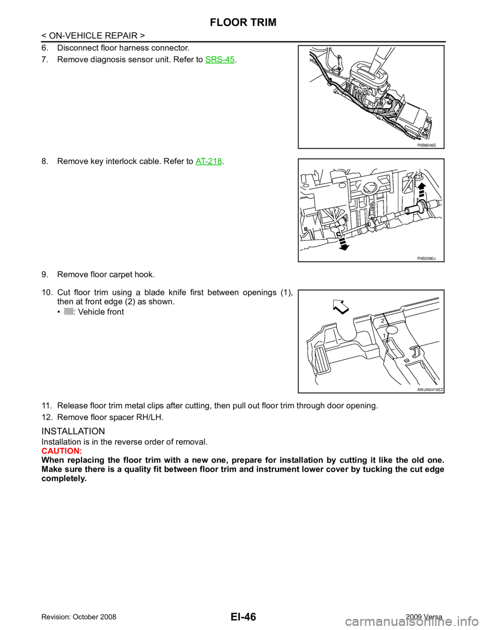
.
8. Remove key interlock cable. Refer to AT-218 .
9. Remove floor carpet hook.
10. Cut floor trim using a blade knife first between openings (1), then at front edge (2) as shown.
• : Vehicle front
11. Release floor trim metal clips after cutting, then pull out floor trim through door opening.
12. Remove floor spacer RH/LH.
INSTALLATION
Installation is in the reverse order of removal.
CAUTION:
When replacing the floor trim with a new one, prepar e for installation by cutting it like the old one.
Make sure there is a quality fit between floor trim and instrument lower cover by tucking the cut edge
completely. PIIB2580J