2009 NISSAN TIIDA key
[x] Cancel search: keyPage 3000 of 4331
EM
NP
O
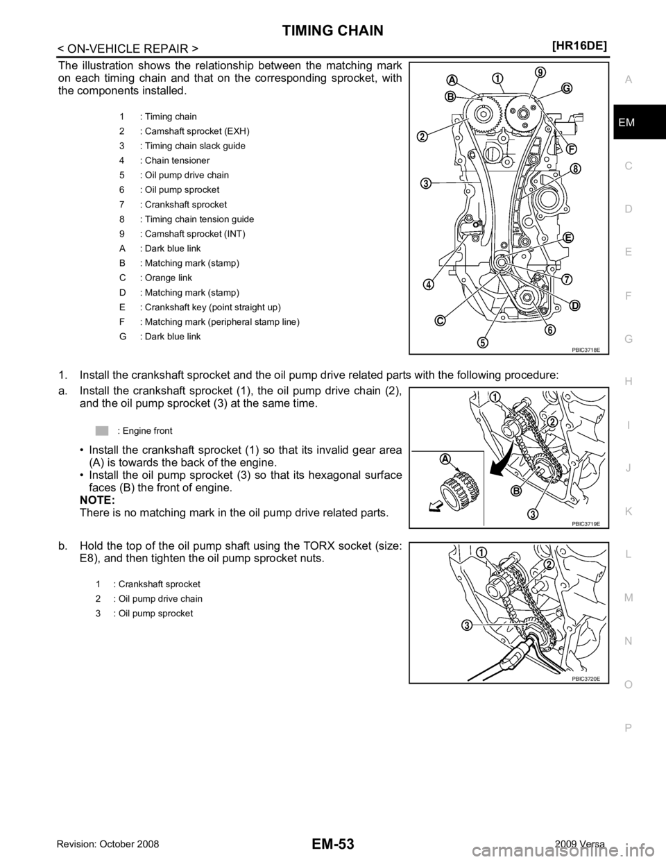
The illustration shows the relationship between the matching mark
on each timing chain and that on the corresponding sprocket, with
the components installed.
1. Install the crankshaft sprocket and the oil pump drive related parts with the following procedure:
a. Install the crankshaft sprocket (1), the oil pump drive chain (2), and the oil pump sprocket (3) at the same time.
• Install the crankshaft sprocket (1) so that its invalid gear area (A) is towards the back of the engine.
• Install the oil pump sprocket (3) so that its hexagonal surface
faces (B) the front of engine.
NOTE:
There is no matching mark in the oil pump drive related parts.
b. Hold the top of the oil pump shaft using the TORX socket (size: E8), and then tighten the oil pump sprocket nuts. 1 : Timing chain
2 : Camshaft sprocket (EXH)
3 : Timing chain slack guide
4 : Chain tensioner
5 : Oil pump drive chain
6 : Oil pump sprocket
7 : Crankshaft sprocket
8 : Timing chain tension guide
9 : Camshaft sprocket (INT)
A : Dark blue link
B : Matching mark (stamp)
C : Orange link
D : Matching mark (stamp)
E : Crankshaft key (point straight up)
F : Matching mark (peripheral stamp line)
G : Dark blue link
Page 3003 of 4331
![NISSAN TIIDA 2009 Service Repair Manual EM-56< ON-VEHICLE REPAIR >
[HR16DE]
TIMING CHAIN
c. Tighten bolts in the numerical order shown.
d. After all bolts are tightened, retighten them to specified torque in numerical order as shown.
CAUTIO NISSAN TIIDA 2009 Service Repair Manual EM-56< ON-VEHICLE REPAIR >
[HR16DE]
TIMING CHAIN
c. Tighten bolts in the numerical order shown.
d. After all bolts are tightened, retighten them to specified torque in numerical order as shown.
CAUTIO](/manual-img/5/57398/w960_57398-3002.png)
EM-56< ON-VEHICLE REPAIR >
[HR16DE]
TIMING CHAIN
c. Tighten bolts in the numerical order shown.
d. After all bolts are tightened, retighten them to specified torque in numerical order as shown.
CAUTION:
Be sure to wipe off any excessive liquid gasket leaking to
surface.
8. Insert crankshaft pulley by aligning with crankshaft key. • When inserting crankshaft pulley with a plastic hamme r, tap on its center portion (not circumference).
CAUTION:
Never damage front oil seal lip section.
9. Tighten crankshaft pulley bolt with the following procedure: • Secure crankshaft pulley with a suitable tool, and tighten crankshaft pulley bolt.
a. Apply new engine oil to thread and seat surfaces of crankshaft pulley bolt.
b. Tighten crankshaft pulley bolt.
c. Put a paint mark (B) on crankshaft pulley, mating with any one of six easy to recognize angle marks (A) on crankshaft bolt flange
(1).
d. Turn another 60 degrees clockwise (angle tightening). • Check the tightening angle with movement of one angle mark.
10. Make sure that crankshaft turns smoothly by rotating by hand clockwise.
11. Installation of the remaining components is in the reverse order of removal.
Inspection INFOID:0000000004784298
INSPECTION AFTER REMOVAL
Timing Chain KBIA3429J
Crankshaft pulley bolt : 35.0 N·m (3.6 kg-m, 26 ft-lb)
PBIC3726E
Page 3014 of 4331
![NISSAN TIIDA 2009 Service Repair Manual CAMSHAFT
EM-67
< ON-VEHICLE REPAIR >
[HR16DE] C
D E
F
G H
I
J
K L
M A EM
NP
O
14. Install timing chain with the following procedure.
• Install by aligning matching marks on each sprocket and NISSAN TIIDA 2009 Service Repair Manual CAMSHAFT
EM-67
< ON-VEHICLE REPAIR >
[HR16DE] C
D E
F
G H
I
J
K L
M A EM
NP
O
14. Install timing chain with the following procedure.
• Install by aligning matching marks on each sprocket and](/manual-img/5/57398/w960_57398-3013.png)
CAMSHAFT
EM-67
< ON-VEHICLE REPAIR >
[HR16DE] C
D E
F
G H
I
J
K L
M A EM
NP
O
14. Install timing chain with the following procedure.
• Install by aligning matching marks on each sprocket and tim-ing chain.
• If these matching marks are not aligned, rotate the camshaft
slightly to correct the position.
CAUTION:
• Check matching mark positi on of each sprocket and tim-
ing chain again after instal ling the timing chain, keep
matching marks aligned by holding them with a hand.
• To avoid skipped teeth, never rotate crankshaft and cam-
shaft until front cover is installed.
15. Install timing chain tension guide (2) and timing chain slack guide (1).
16. Install chain tensioner (1). • Fix the plunger at the most compressed position using a stop-per pin (A), and then install it.
• Securely pull out the stopper pin after installing the chain ten-
sioner.
17. Check matching mark position of timing chain and each sprocket again. A : Dark blue link
B : Matching mark (stamp)
C : Orange link
D : Matching mark (stamp)
E : Crankshaft key (point straight up)
F : Matching mark (peripheral stamp line)
G : Dark blue link PBIC3721E
PBIC3714E
PBIC3722E
Page 3017 of 4331
![NISSAN TIIDA 2009 Service Repair Manual EM-70< ON-VEHICLE REPAIR >
[HR16DE]
CAMSHAFT
c. Tighten bolts in the numerical order shown.
d. After all bolts are tightened, retighten them to specified torque in numerical order as shown.
CAUTION:
B NISSAN TIIDA 2009 Service Repair Manual EM-70< ON-VEHICLE REPAIR >
[HR16DE]
CAMSHAFT
c. Tighten bolts in the numerical order shown.
d. After all bolts are tightened, retighten them to specified torque in numerical order as shown.
CAUTION:
B](/manual-img/5/57398/w960_57398-3016.png)
EM-70< ON-VEHICLE REPAIR >
[HR16DE]
CAMSHAFT
c. Tighten bolts in the numerical order shown.
d. After all bolts are tightened, retighten them to specified torque in numerical order as shown.
CAUTION:
Be sure to wipe off any excessive liquid gasket leaking to
surface.
22. Insert crankshaft pulley by aligning with crankshaft key. • When inserting crankshaft pulley with a plastic hamme r, tap on its center portion (not circumference).
CAUTION:
Never damage front oil seal lip section.
23. Tighten crankshaft pulley bolt with the following procedure: • Secure crankshaft pulley with a suitable tool, and tighten crankshaft pulley bolt.
a. Apply new engine oil to thread and seat surfaces of crankshaft pulley bolt.
b. Tighten crankshaft pulley bolt.
c. Put a paint mark (B) on crankshaft pulley, mating with any one of six easy to recognize angle marks (A) on crankshaft bolt flange
(1).
d. Turn another 60 degrees clockwise (angle tightening). • Check the tightening angle with movement of one angle mark.
24. Make sure that crankshaft turns smoothly by rotating by hand clockwise.
25. Install the camshaft position sensor (PHASE) to the rear end of cylinder head.
• Tighten bolts with it seated completely.
26. Check and adjust valve clearance. Refer to EM-20, " Inspection and Adjustment " .
27. Installation of the remaining components is in the reverse order of removal.
Inspection INFOID:0000000004784301
INSPECTION AFTER REMOVAL
Oil Filter KBIA3429J
Crankshaft pulley bolt : 35.0 N·m (3.6 kg-m, 26 ft-lb)
PBIC3726E
Page 3043 of 4331
Removal and Installation " .
2. Remove knock sensor. CAUTION:
Carefully handle knock sensor avoiding shocks.
3. Remove crankshaft position sensor (POS) and cover. CAUTION:
• Avoid impacts such as a dropping.
• Never disassemble.
• Keep it away from metal particles.
• Never place the sensor where it is exposed to magnetism.
4. Remove piston and connecting rod assembly with the following procedure: • Before removing piston and connecting rod assembly, check the connecting rod side clearance. Refer to
EM-103, " Inspection " .
a. Position crankshaft pin corresponding to connecting rod to be removed onto the bottom dead center.
b. Remove connecting rod cap.
c. Using a hammer handle or similar tool, push piston and connect- ing rod assembly out to the cylinder head side.
CAUTION:
• Be careful not to damage matching surface with connect-
ing rod cap.
• Be careful not to damage the cylinder wall and crankshaft pin, resulting from an inte rference of the connecting rod
big end.
5. Remove connecting rod bearings. CAUTION:
Identify installation positions, and store them without mixing up.
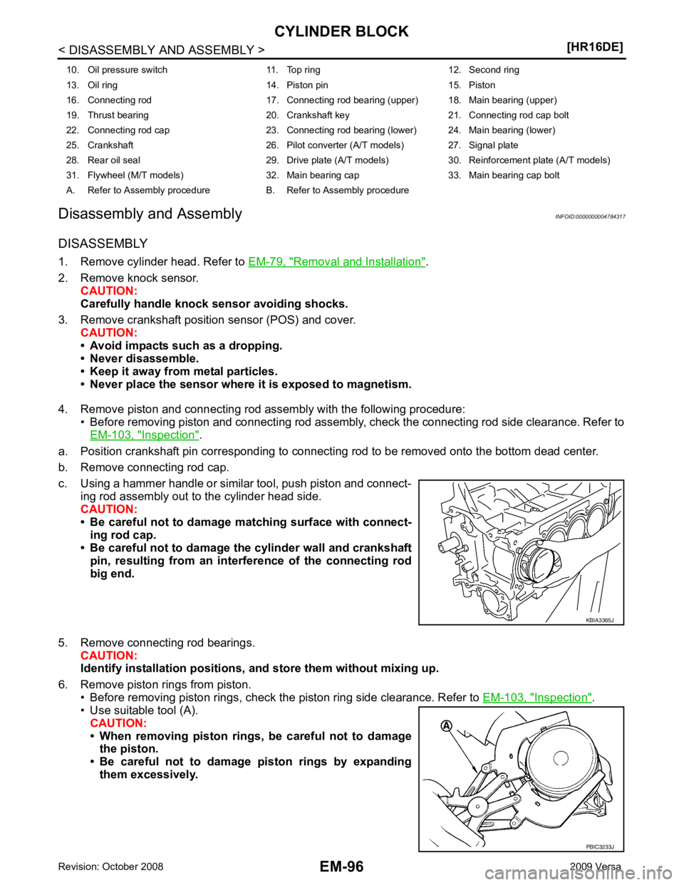
6. Remove piston rings from piston. • Before removing piston rings, check the piston ring side clearance. Refer to EM-103, " Inspection " .
• Use suitable tool (A).
CAUTION:
• When removing piston rings, be careful not to damage the piston.
• Be careful not to damage piston rings by expanding
them excessively.
10. Oil pressure switch 11. Top ring 12. Second ring
13. Oil ring 14. Piston pin 15. Piston
16. Connecting rod 17. Connecting rod bearing (upper) 18. Main bearing (upper)
19. Thrust bearing 20. Crankshaft key 21. Connecting rod cap bolt
22. Connecting rod cap 23. Connecting rod bearing (lower) 24. Main bearing (lower)
25. Crankshaft 26. Pilot converter (A/T models) 27. Signal plate
28. Rear oil seal 29. Drive plate (A/T models) 30. Reinforcement plate (A/T models)
31. Flywheel (M/T models) 32. Main bearing cap 33. Main bearing cap bolt
A. Refer to Assembly procedure B. Refer to Assembly procedure PBIC3233J
Page 3112 of 4331
EM
NP
O
• Check timing chain and oil pump drive chain for cracks (A) and any
excessive wear (B) at the roller links of timing chain.
• Replace timing chain and/or oil pump drive chain if necessary.
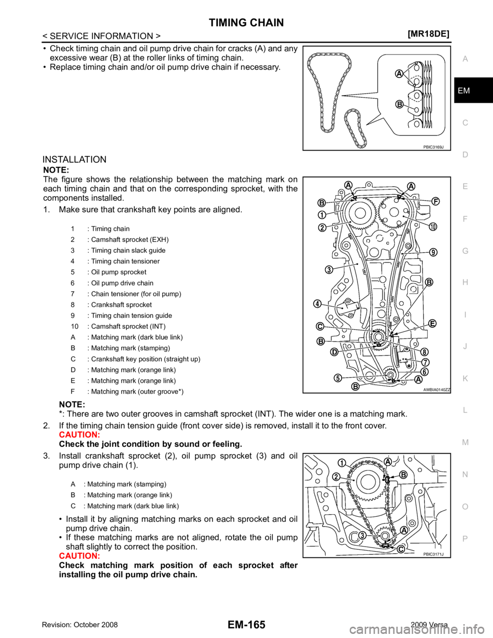
INSTALLATION NOTE:
The figure shows the relationship between the matching mark on
each timing chain and that on the corresponding sprocket, with the
components installed.
1. Make sure that crankshaft key points are aligned.
NOTE:
*: There are two outer grooves in camshaft spro cket (INT). The wider one is a matching mark.
2. If the timing chain tension guide (front cover si de) is removed, install it to the front cover.
CAUTION:
Check the joint condition by sound or feeling.
3. Install crankshaft sprocket (2), oil pump sprocket (3) and oil pump drive chain (1).
• Install it by aligning matching marks on each sprocket and oil pump drive chain.
• If these matching marks are not aligned, rotate the oil pump
shaft slightly to correct the position.
CAUTION:
Check matching mark position of each sprocket after
installing the oil pump drive chain. PBIC3171J
Page 3147 of 4331
.
2. Install engine to engine stand as follows;
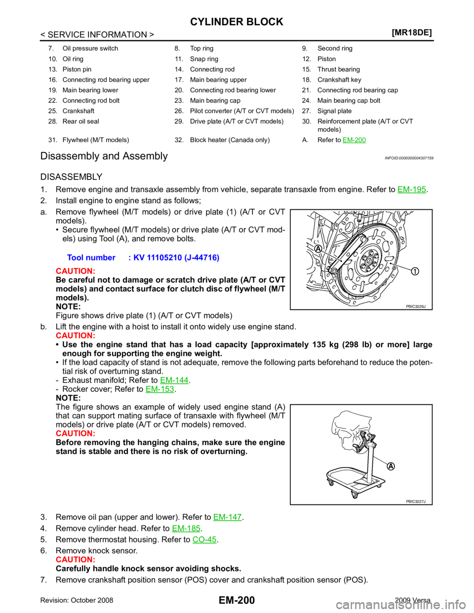
a. Remove flywheel (M/T models) or drive plate (1) (A/T or CVT models).
• Secure flywheel (M/T models) or drive plate (A/T or CVT mod-
els) using Tool (A), and remove bolts.
CAUTION:
Be careful not to damage or scratch drive plate (A/T or CVT
models) and contact surface for clutch disc of flywheel (M/T
models).
NOTE:
Figure shows drive plate (1) (A/T or CVT models)
b. Lift the engine with a hoist to install it onto widely use engine stand. CAUTION:
• Use the engine stand that has a load capacity [approximately 135 kg (298 lb) or more] large
enough for supporting the engine weight.
• If the load capacity of stand is not adequate, remo ve the following parts beforehand to reduce the poten-
tial risk of overturning stand.
- Exhaust manifold; Refer to EM-144 .
- Rocker cover; Refer to EM-153 .
NOTE:
The figure shows an example of widely used engine stand (A)
that can support mating surface of transaxle with flywheel (M/T
models) or drive plate (A/T or CVT models) removed.
CAUTION:
Before removing the hanging chains, make sure the engine
stand is stable and there is no risk of overturning.
3. Remove oil pan (upper and lower). Refer to EM-147 .
4. Remove cylinder head. Refer to EM-185 .
5. Remove thermostat housing. Refer to CO-45 .
6. Remove knock sensor. CAUTION:
Carefully handle knock sensor avoiding shocks.
7. Remove crankshaft position sensor (POS) cover and crankshaft position sensor (POS).
7. Oil pressure switch 8. Top ring 9. Second ring
10. Oil ring 11. Snap ring 12. Piston
13. Piston pin 14. Connecting rod 15. Thrust bearing
16. Connecting rod bearing upper 17. Main bearing upper 18. Crankshaft key
19. Main bearing lower 20. Connecting rod bearing lower 21. Connecting rod bearing cap
22. Connecting rod bolt 23. Main bearing cap 24. Main bearing cap bolt
25. Crankshaft 26. Pilot converter (A/T or CVT models) 27. Signal plate
28. Rear oil seal 29. Drive plate (A/T or CVT models) 30. Reinforcement plate (A/T or CVT models)
31. Flywheel (M/T models) 32. Block heater (Canada only) A. Refer to EM-200 PBIC3227J
Page 3191 of 4331
EX
NP
O
SERVICE INFORMATION
PRECAUTIONS
Precaution for Supplemental Restraint System (SRS) "AIR BAG" and "SEAT BELT
PRE-TENSIONER" INFOID:0000000004784390
The Supplemental Restraint System such as “A IR BAG” and “SEAT BELT PRE-TENSIONER”, used along
with a front seat belt, helps to reduce the risk or severi ty of injury to the driver and front passenger for certain
types of collision. This system includes seat belt switch inputs and dual stage front air bag modules. The SRS
system uses the seat belt switches to determine the front air bag deployment, and may only deploy one front
air bag, depending on the severity of a collision and w hether the front occupants are belted or unbelted.
Information necessary to service the system safely is included in the SRS and SB section of this Service Man-
ual.
WARNING:
• To avoid rendering the SRS inoper ative, which could increase the risk of personal injury or death in
the event of a collision which would result in air bag inflation, all maintenance must be performed by
an authorized NISSAN/INFINITI dealer.
• Improper maintenance, including in correct removal and installation of the SRS can lead to personal
injury caused by unintentional act ivation of the system. For removal of Spiral Cable and Air Bag
Module, see the SRS section.
• Do not use electrical test equipm ent on any circuit related to the SRS unless instructed to in this
Service Manual. SRS wiring harnesses can be identi fied by yellow and/or orange harnesses or har-
ness connectors.
• When working near the Airbag Diagnosis Sensor Un it or other Airbag System sensors with the Igni-
tion ON or engine running, DO NOT use air or el ectric power tools or strike near the sensor(s) with a
hammer. Heavy vibration could activate the sensor( s) and deploy the air bag(s), possibly causing
serious injury.
• When using air or electric power tools or hammers , always switch the Ignition OFF, disconnect the
battery, and wait at least 3 minutes before performing any service.
Precaution Necessary for Steering Wh eel Rotation After Battery Disconnect
INFOID:0000000004675325
NOTE:
• This Procedure is applied only to models with Inte lligent Key system and NATS (NISSAN ANTI-THEFT SYS-
TEM).
• Remove and install all control units after disconnecti ng both battery cables with the ignition knob in the
″ LOCK ″ position.
• Always use CONSULT-III to perform self-diagnosis as a part of each function inspection after finishing work.
If DTC is detected, perform trouble diagnosis according to self-diagnostic results.
For models equipped with the Intelligent Key system and NATS , an electrically controlled steering lock mech-
anism is adopted on the key cylinder.
For this reason, if the battery is disconnected or if the battery is discharged, the steering wheel will lock and
steering wheel rotation will become impossible.
If steering wheel rotation is required when battery pow er is interrupted, follow the procedure below before
starting the repair operation.
OPERATION PROCEDURE 1. Connect both battery cables. NOTE:
Supply power using jumper cables if battery is discharged.
2. Use the Intelligent Key or mechanical key to turn the ignition switch to the ″ACC ″ position. At this time, the
steering lock will be released.
3. Disconnect both battery cables. The steering lock will remain released and the steering wheel can be
rotated.
4. Perform the necessary repair operation.
5. When the repair work is completed, return the ignition switch to the ″LOCK ″ position before connecting
the battery cables. (At this time, the steering lock mechanism will engage.)
6. Perform a self-diagnosis check of al l control units using CONSULT-III.