2009 NISSAN TIIDA key
[x] Cancel search: keyPage 3746 of 4331

MA
N
O P
SERVICE INFORMATION
PRECAUTIONS
Precaution for Supplemental Restraint System (SRS) "AIR BAG" and "SEAT BELT
PRE-TENSIONER" INFOID:0000000004803408
The Supplemental Restraint System such as “A IR BAG” and “SEAT BELT PRE-TENSIONER”, used along
with a front seat belt, helps to reduce the risk or severi ty of injury to the driver and front passenger for certain
types of collision. This system includes seat belt switch inputs and dual stage front air bag modules. The SRS
system uses the seat belt switches to determine the front air bag deployment, and may only deploy one front
air bag, depending on the severity of a collision and w hether the front occupants are belted or unbelted.
Information necessary to service the system safely is included in the SRS and SB section of this Service Man-
ual.
WARNING:
• To avoid rendering the SRS inoper ative, which could increase the risk of personal injury or death in
the event of a collision which would result in air bag inflation, all maintenance must be performed by
an authorized NISSAN/INFINITI dealer.
• Improper maintenance, including in correct removal and installation of the SRS can lead to personal
injury caused by unintentional act ivation of the system. For removal of Spiral Cable and Air Bag
Module, see the SRS section.
• Do not use electrical test equipm ent on any circuit related to the SRS unless instructed to in this
Service Manual. SRS wiring harnesses can be identi fied by yellow and/or orange harnesses or har-
ness connectors.
PRECAUTIONS WHEN USING POWER TOOLS (AIR OR ELECTRIC) AND HAMMERS WARNING:
• When working near the Airbag Diagnosis Sensor Un it or other Airbag System sensors with the Igni-
tion ON or engine running, DO NOT use air or el ectric power tools or strike near the sensor(s) with a
hammer. Heavy vibration could activate the sensor( s) and deploy the air bag(s), possibly causing
serious injury.
• When using air or electric power tools or hammers , always switch the Ignition OFF, disconnect the
battery, and wait at least 3 minutes before performing any service.
Precaution Necessary for Steering Wh eel Rotation After Battery Disconnect
INFOID:0000000004803409
NOTE:
• This Procedure is applied only to models with Inte lligent Key system and NATS (NISSAN ANTI-THEFT SYS-
TEM).
• Remove and install all control units after disconnecti ng both battery cables with the ignition knob in the
″ LOCK ″ position.
• Always use CONSULT-III to perform self-diagnosis as a part of each function inspection after finishing work.
If DTC is detected, perform trouble diagnosis according to self-diagnostic results.
For models equipped with the Intelligent Key system and NATS , an electrically controlled steering lock mech-
anism is adopted on the key cylinder.
For this reason, if the battery is disconnected or if the battery is discharged, the steering wheel will lock and
steering wheel rotation will become impossible.
If steering wheel rotation is required when battery pow er is interrupted, follow the procedure below before
starting the repair operation.
OPERATION PROCEDURE 1. Connect both battery cables. NOTE:
Supply power using jumper cables if battery is discharged.
2. Use the Intelligent Key or mechanical key to turn the ignition switch to the ″ACC ″ position. At this time, the
steering lock will be released.
3. Disconnect both battery cables. The steering lock will remain released and the steering wheel can be
rotated.
4. Perform the necessary repair operation.
Page 3825 of 4331
![NISSAN TIIDA 2009 Service Repair Manual TRANSAXLE ASSEMBLY
MT-31
< SERVICE INFORMATION >
[RS5F91R] D
E
F
G H
I
J
K L
M A
B MT
N
O P
24. Install lock pins ( ) to clutch housing.
25. Install 3rd-4th shift fork to 3rd-4th fork rod, and NISSAN TIIDA 2009 Service Repair Manual TRANSAXLE ASSEMBLY
MT-31
< SERVICE INFORMATION >
[RS5F91R] D
E
F
G H
I
J
K L
M A
B MT
N
O P
24. Install lock pins ( ) to clutch housing.
25. Install 3rd-4th shift fork to 3rd-4th fork rod, and](/manual-img/5/57398/w960_57398-3824.png)
TRANSAXLE ASSEMBLY
MT-31
< SERVICE INFORMATION >
[RS5F91R] D
E
F
G H
I
J
K L
M A
B MT
N
O P
24. Install lock pins ( ) to clutch housing.
25. Install 3rd-4th shift fork to 3rd-4th fork rod, and then install retaining pin to 3rd-4th shift fork.
CAUTION:
• Never reuse retaining pin.
• Replace 3rd-4th fork rod and 3rd-4th shift fork as a set.
26. Install 3rd-4th fork rod assembly (1), 3rd-4th coupling sleeve (2), and input shaft assembly (3) to clutch housing according to the
following procedures.
a. Pull 1st-2nd fork rod (4) up, and then maintain the neutral posi- tion.
b. Set 3rd-4th fork rod assembly onto 3rd-4th coupling sleeve, and then install them together with input shaft assembly to clutch
housing.
CAUTION:
• Set lock pin (3rd-4th fork rod side) onto 1st-2nd fork rod groove and then install 3rd-4th fork rod assembly.
• Be careful with the orientat ion of 3rd-4th coupling sleeve.
- A: 4th main gear side
- B: 3rd main gear side
• Install 3rd input gear of in put shaft assembly so that it is
set under reverse main gear of 3rd-4th coupling sleeve.
• Replace 3rd-4th coupling sl eeve and 3rd-4th synchronizer
hub as a set.
c. Install springs and insert keys to 3rd-4th synchronizer hub.
d. Apply gear oil to 4th baulk ring.
e. Install 4th baulk ring.
27. Install 5th-reverse fork rod (1) to clutch housing according to the following procedures.
CAUTION:
Replace 5th-reverse fork rod and 5th-reverse shift fork as a
set.
a. Pull gear of reverse gear assembly (2) up.
b. Temporarily install 5th-reverse fork rod to clutch housing. JPDIC0534ZZ
PCIB1628E
PCIB1551E
MCIB0061E
PCIB1629E
Page 3845 of 4331

MT
N
O P
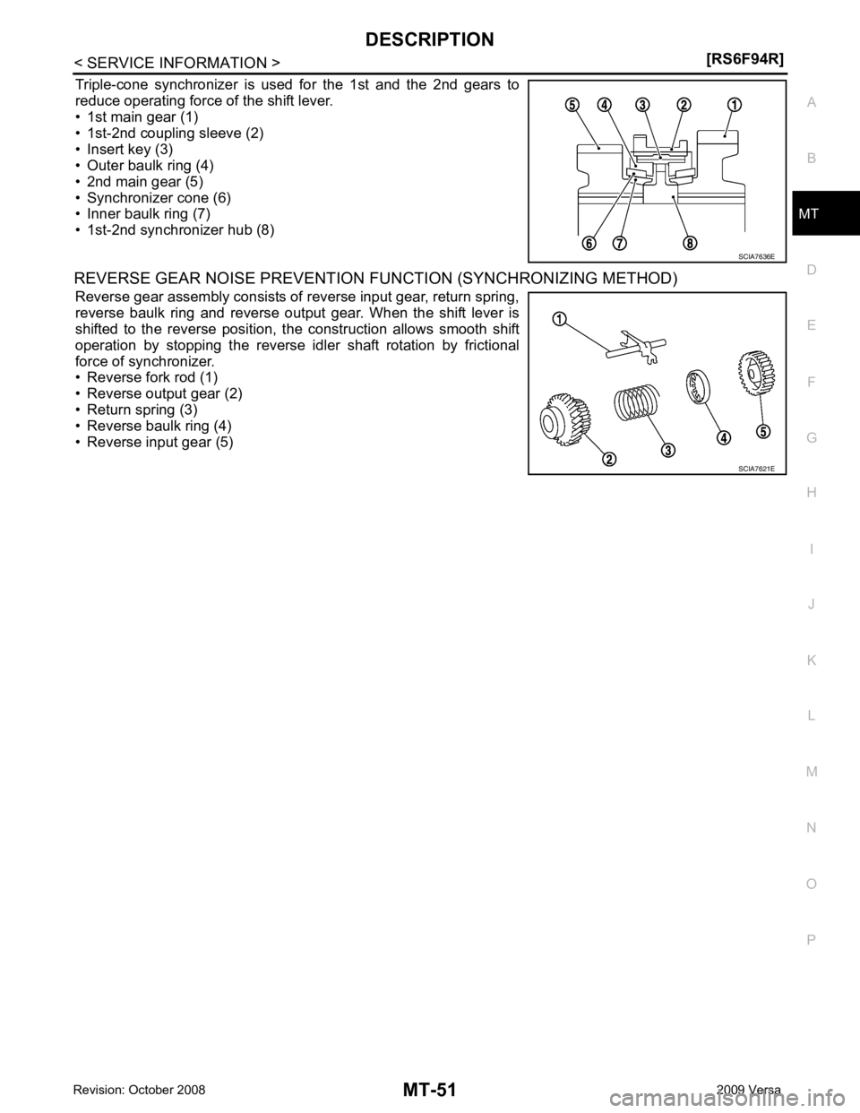
Triple-cone synchronizer is used for the 1st and the 2nd gears to
reduce operating force of the shift lever.
• 1st main gear (1)
• 1st-2nd coupling sleeve (2)
• Insert key (3)
• Outer baulk ring (4)
• 2nd main gear (5)
• Synchronizer cone (6)
• Inner baulk ring (7)
• 1st-2nd synchronizer hub (8)
REVERSE GEAR NOISE PREVENTION FUNCTION (SYNCHRONIZING METHOD)
Reverse gear assembly consists of reverse input gear, return spring,
reverse baulk ring and reverse output gear. When the shift lever is
shifted to the reverse position, the construction allows smooth shift
operation by stopping the reverse idler shaft rotation by frictional
force of synchronizer.
• Reverse fork rod (1)
• Reverse output gear (2)
• Return spring (3)
• Reverse baulk ring (4)
• Reverse input gear (5) SCIA7621E
Page 3855 of 4331

MT
N
O P
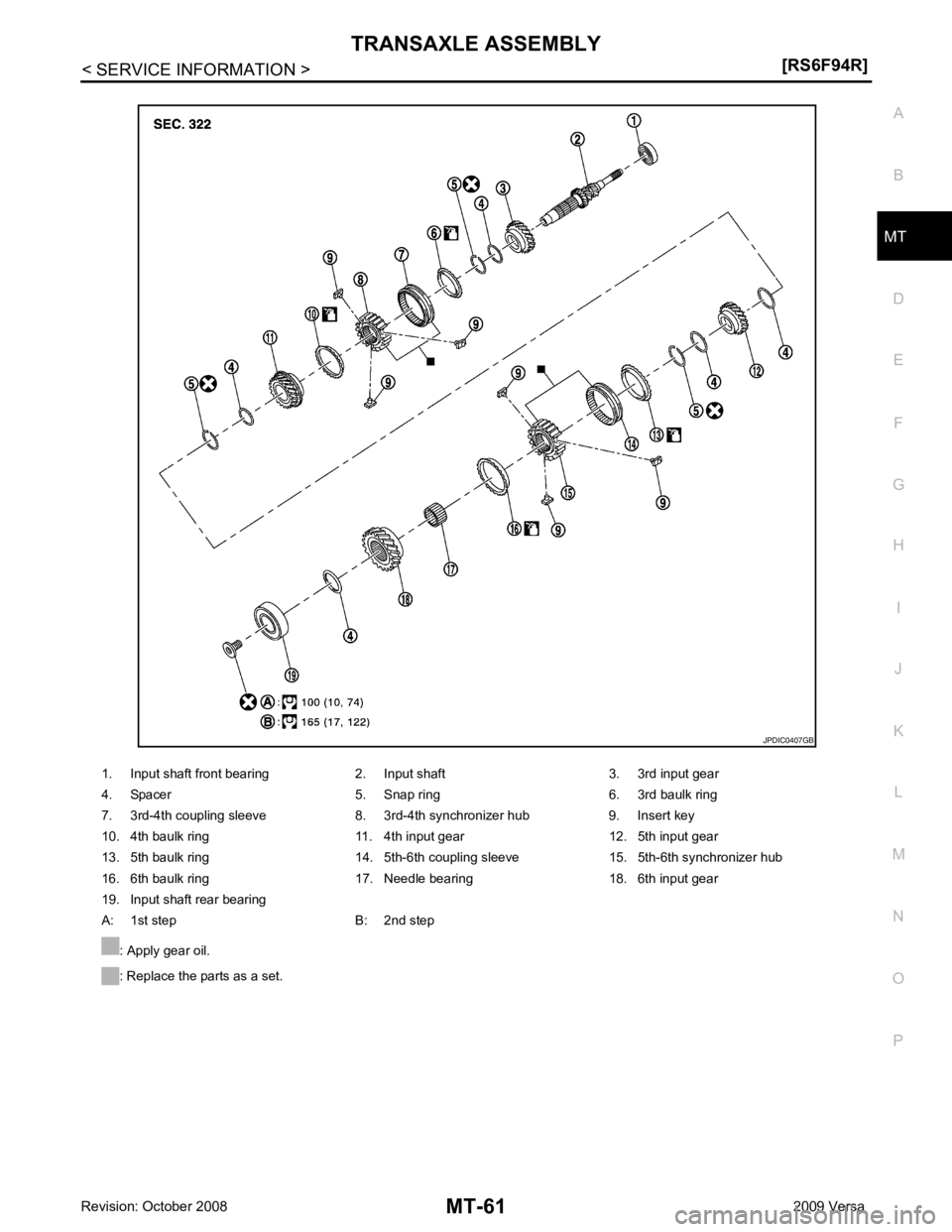
1. Input shaft front bearing 2. Input shaft 3. 3rd input gear
4. Spacer 5. Snap ring 6. 3rd baulk ring
7. 3rd-4th coupling sleeve 8. 3rd-4th synchronizer hub 9. Insert key
10. 4th baulk ring 11. 4th input gear 12. 5th input gear
13. 5th baulk ring 14. 5th-6th coupling sleeve 15. 5th-6th synchronizer hub
16. 6th baulk ring 17. Needle bearing 18. 6th input gear
19. Input shaft rear bearing
A: 1st step B: 2nd step
: Apply gear oil.
: Replace the parts as a set.
Page 3870 of 4331
![NISSAN TIIDA 2009 Service Repair Manual MT-76< SERVICE INFORMATION >
[RS6F94R]
INPUT SHAFT AND GEARS
INPUT SHAFT AND GEARS
Disassembly and Assembly INFOID:0000000004305280
GENERAL PRECAUTIONS
• Never reuse snap ring.
• Secure input shaf NISSAN TIIDA 2009 Service Repair Manual MT-76< SERVICE INFORMATION >
[RS6F94R]
INPUT SHAFT AND GEARS
INPUT SHAFT AND GEARS
Disassembly and Assembly INFOID:0000000004305280
GENERAL PRECAUTIONS
• Never reuse snap ring.
• Secure input shaf](/manual-img/5/57398/w960_57398-3869.png)
MT-76< SERVICE INFORMATION >
[RS6F94R]
INPUT SHAFT AND GEARS
INPUT SHAFT AND GEARS
Disassembly and Assembly INFOID:0000000004305280
GENERAL PRECAUTIONS
• Never reuse snap ring.
• Secure input shaft in a vise with backplate, and then remove gears and snap rings.
• For installation and removal of snap ring, set snap ring pliers and flat pliers at both sides of snap ring. While expanding snap ring
with snap ring pliers, move snap ring with flat pliers.
• Disassemble gear components putting direction marks on the parts that do not affect any functions.
DISASSEMBLY
1. Remove input shaft rear bearing bolt (1) using Tool (A).
2. Remove input shaft rear bearing (1) according to the following procedures.
a. Set a suitable puller to input shaft rear bearing.
b. Remove input shaft rear bearing using a suitable drift (A).
3. Remove spacer (1), 6th input gear (2), needle bearing, 6th baulk ring, and 5th-6th synchronizer hub assembly (3).
4. Remove insert keys and 5th-6th coupling sleeve from 5th-6th synchronizer hub. SCIA1755J
Tool number A: KV32300QAM ( — )
JPDIC0449ZZ
JPDIC0111ZZ
PCIB1750E
Page 3871 of 4331

MT
N
O P
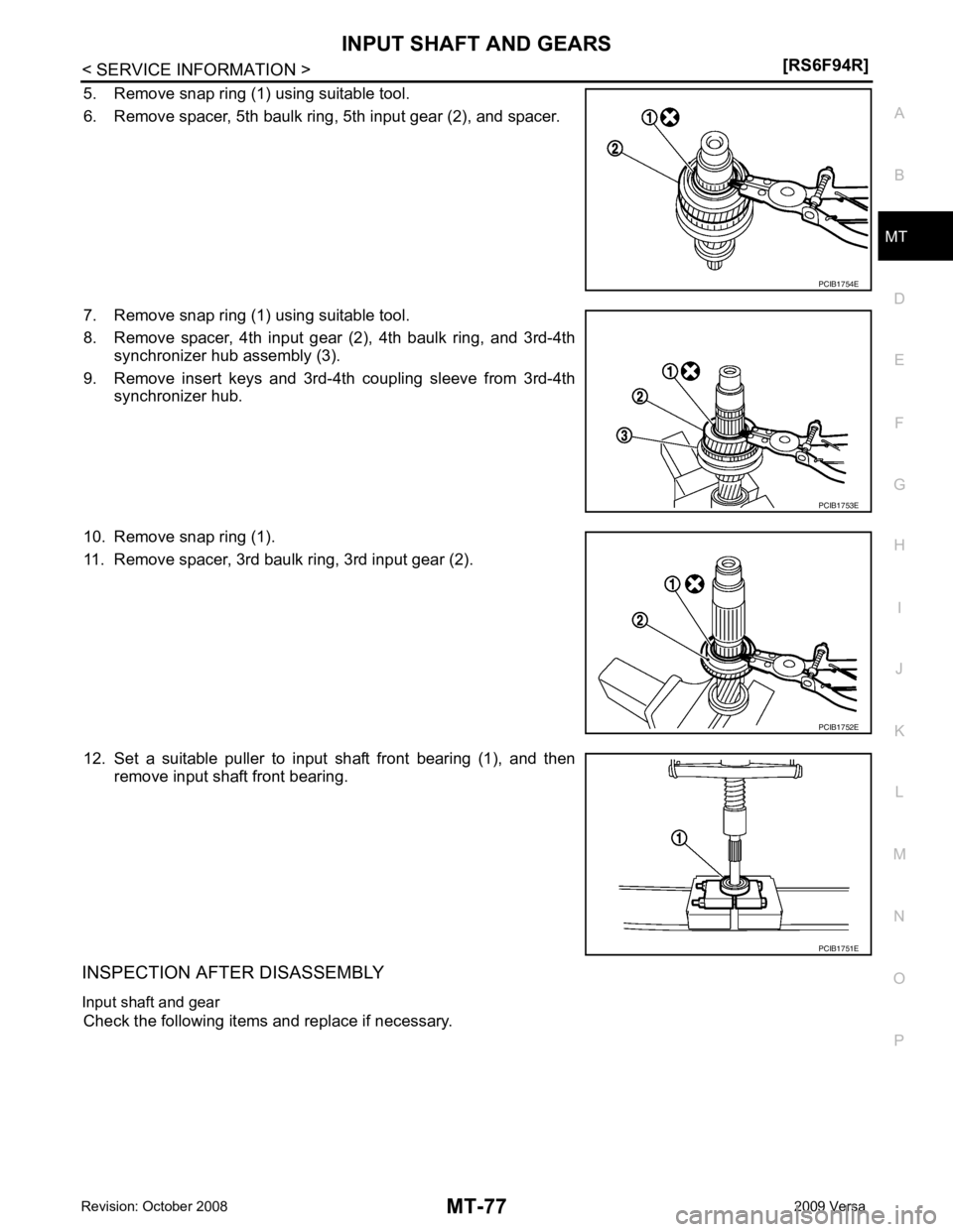
5. Remove snap ring (1) using suitable tool.
6. Remove spacer, 5th baulk ring, 5th input gear (2), and spacer.
7. Remove snap ring (1) using suitable tool.
8. Remove spacer, 4th input gear (2), 4th baulk ring, and 3rd-4th synchronizer hub assembly (3).
9. Remove insert keys and 3rd-4th coupling sleeve from 3rd-4th synchronizer hub.
10. Remove snap ring (1).
11. Remove spacer, 3rd baulk ring, 3rd input gear (2).
12. Set a suitable puller to input shaft front bearing (1), and then remove input shaft front bearing.
INSPECTION AFTER DISASSEMBLY
Input shaft and gear Check the following items and replace if necessary. PCIB1753E
PCIB1752E
Page 3872 of 4331
![NISSAN TIIDA 2009 Service Repair Manual MT-78< SERVICE INFORMATION >
[RS6F94R]
INPUT SHAFT AND GEARS
• Damage, peeling, bend, uneven wear, and distortion of shaft.
• Excessive wear, damage, and peeling of gear.
Synchronizer
• Synchron NISSAN TIIDA 2009 Service Repair Manual MT-78< SERVICE INFORMATION >
[RS6F94R]
INPUT SHAFT AND GEARS
• Damage, peeling, bend, uneven wear, and distortion of shaft.
• Excessive wear, damage, and peeling of gear.
Synchronizer
• Synchron](/manual-img/5/57398/w960_57398-3871.png)
MT-78< SERVICE INFORMATION >
[RS6F94R]
INPUT SHAFT AND GEARS
• Damage, peeling, bend, uneven wear, and distortion of shaft.
• Excessive wear, damage, and peeling of gear.
Synchronizer
• Synchronizer hub and coupling sleeve Check the following items and replace if necessary.
- Breakage, damage, and unusual wear on contact surface of cou-
pling sleeve, synchronizer hub, and insert key.
- Coupling sleeve and synchronizer hub move smoothly.
• Baulk ring Check contact surface of baulk ring cam and insert key for exces-
sive wear, uneven wear, bend, and damage. Replace if necessary.
Bearing
Check bearing for damage and unsmooth rotation. Replace if neces-
sary.
ASSEMBLY
Note the following procedures, and assemble in the reverse order of disassembly.
CAUTION:
• Replace transaxle assembly when replacing input shaft.
• Never reuse snap ring.
• Check that snap ring is securely installed in a groove.
• Replace 3rd-4th coupling sleeve and 3rd-4th synchronizer hub as a set. SCIA7736E
SCIA1753J
SCIA0608J
MTF0041D
Page 3877 of 4331
![NISSAN TIIDA 2009 Service Repair Manual MAINSHAFT AND GEARS
MT-83
< SERVICE INFORMATION >
[RS6F94R] D
E
F
G H
I
J
K L
M A
B MT
N
O P
Check contact surface of baulk ring cam and insert key for exces-
sive wear, uneven wear, bend, and damage. NISSAN TIIDA 2009 Service Repair Manual MAINSHAFT AND GEARS
MT-83
< SERVICE INFORMATION >
[RS6F94R] D
E
F
G H
I
J
K L
M A
B MT
N
O P
Check contact surface of baulk ring cam and insert key for exces-
sive wear, uneven wear, bend, and damage.](/manual-img/5/57398/w960_57398-3876.png)
MAINSHAFT AND GEARS
MT-83
< SERVICE INFORMATION >
[RS6F94R] D
E
F
G H
I
J
K L
M A
B MT
N
O P
Check contact surface of baulk ring cam and insert key for exces-
sive wear, uneven wear, bend, and damage. Replace if necessary.
Bearing Check bearing for damage and unsmooth rotation. Replace if neces-
sary.
CAUTION:
• Replace mainshaft front bearing outer race and mainshaft
front bearing inner race as a set.
• Replace mainshaft rear bearin g inner race and mainshaft rear
bearing outer race as a set.
ASSEMBLY CAUTION:
• Select mainshaft rear bearing adjusting shim acco rding to the following procedures when replacing
mainshaft adjusting shim, 6th main gear , 5th main gear, or 4th main gear.
- Replace mainshaft adjusting shim.
• If new mainshaft adjusting shim is thinner than previous one, offset the thickness difference by
selecting thicker mainshaft r ear bearing adjusting shim.
• If new mainshaft adjusting shim is thicker th an previous one, offset the thickness difference by
selecting thinner mainshaft rear bearing adjusting shim.
- Replace 6th main gear, 5th main gear, or 4th main gear.
• Measure the thickness of the main gear used before and the new main gear
• Increase the thickness of the mainsh aft rear bearing adjusting shim, if the difference is smaller than
0.025 mm (0.0010 in).
• Replace transaxle assembly when replacing mainshaft.
1. Install mainshaft front bearing inner race (1) using the Tool (A).
CAUTION:
Replace mainshaft front bearing outer race and mainshaft
front bearing inner race as a set.
2. Apply gear oil to 1st inner baulk ring, 1st synchronizer cone, 1st outer baulk ring, 2nd inner baulk ring, 2nd synchronizer cone,
and 2nd outer baulk ring.
CAUTION:
• Replace 1st inner baulk ring, 1st synchronizer cone, and
1st outer baulk ring as a set.
• Replace 2nd inner baulk ring, 2nd synchronize r cone, and 2nd outer baulk ring as a set.
3. Install insert keys and 1st-2nd coupling sleeve to 1st-2nd synchronizer hub. CAUTION:
Replace 1st-2nd synchroni zer hub and 1st-2nd coupling sleeve as a set. SCIA0608J
SPD715
Tool number A: ST36720030 ( — )
PCIB1733E