2009 NISSAN TIIDA key
[x] Cancel search: keyPage 3888 of 4331

MTC
N
O P
SERVICE INFORMATION
PRECAUTIONS
Precaution for Supplemental Restraint System (SRS) "AIR BAG" and "SEAT BELT
PRE-TENSIONER" INFOID:0000000004784399
The Supplemental Restraint System such as “A IR BAG” and “SEAT BELT PRE-TENSIONER”, used along
with a front seat belt, helps to reduce the risk or severi ty of injury to the driver and front passenger for certain
types of collision. This system includes seat belt switch inputs and dual stage front air bag modules. The SRS
system uses the seat belt switches to determine the front air bag deployment, and may only deploy one front
air bag, depending on the severity of a collision and w hether the front occupants are belted or unbelted.
Information necessary to service the system safely is included in the SRS and SB section of this Service Man-
ual.
WARNING:
• To avoid rendering the SRS inoper ative, which could increase the risk of personal injury or death in
the event of a collision which would result in air bag inflation, all maintenance must be performed by
an authorized NISSAN/INFINITI dealer.
• Improper maintenance, including in correct removal and installation of the SRS can lead to personal
injury caused by unintentional act ivation of the system. For removal of Spiral Cable and Air Bag
Module, see the SRS section.
• Do not use electrical test equipm ent on any circuit related to the SRS unless instructed to in this
Service Manual. SRS wiring harnesses can be identi fied by yellow and/or orange harnesses or har-
ness connectors.
PRECAUTIONS WHEN USING POWER TOOLS (AIR OR ELECTRIC) AND HAMMERS WARNING:
• When working near the Airbag Diagnosis Sensor Un it or other Airbag System sensors with the Igni-
tion ON or engine running, DO NOT use air or el ectric power tools or strike near the sensor(s) with a
hammer. Heavy vibration could activate the sensor( s) and deploy the air bag(s), possibly causing
serious injury.
• When using air or electric power tools or hammers , always switch the Ignition OFF, disconnect the
battery, and wait at least 3 minutes before performing any service.
Precaution Necessary for Steering Wh eel Rotation After Battery Disconnect
INFOID:0000000004687764
NOTE:
• This Procedure is applied only to models with Inte lligent Key system and NATS (NISSAN ANTI-THEFT SYS-
TEM).
• Remove and install all control units after disconnecti ng both battery cables with the ignition knob in the
″ LOCK ″ position.
• Always use CONSULT-III to perform self-diagnosis as a part of each function inspection after finishing work.
If DTC is detected, perform trouble diagnosis according to self-diagnostic results.
For models equipped with the Intelligent Key system and NATS , an electrically controlled steering lock mech-
anism is adopted on the key cylinder.
For this reason, if the battery is disconnected or if the battery is discharged, the steering wheel will lock and
steering wheel rotation will become impossible.
If steering wheel rotation is required when battery pow er is interrupted, follow the procedure below before
starting the repair operation.
OPERATION PROCEDURE 1. Connect both battery cables. NOTE:
Supply power using jumper cables if battery is discharged.
2. Use the Intelligent Key or mechanical key to turn the ignition switch to the ″ACC ″ position. At this time, the
steering lock will be released.
3. Disconnect both battery cables. The steering lock will remain released and the steering wheel can be
rotated.
4. Perform the necessary repair operation.
Page 4008 of 4331

PG
N
O P
24 Y Cooling fan relay-3 Output —
Conditions correct for cooling
fan high operation Battery voltage
Conditions not correct for
cooling fan high operation 0V
26 O Tail lamp relay (park-
ing lamps) Output — Lighting switch in 2nd position Battery voltage
27 BR Tail lamp relay (park-
ing lamps) Output — Lighting switch in 2nd position Battery voltage
28 GR Tail lamp relay (park-
ing lamps) Output — Lighting switch in 2nd position Battery voltage
29 P Tail lamp relay (park-
ing lamps) Output — Lighting switch in 2nd position Battery voltage
30
(A/T
only) R Fuse 54 Output — Ignition switch ON or START Battery voltage
Ignition switch OFF or ACC 0V
31 O Fuse 55 Output — Ignition switch ON or START Battery voltage
Ignition switch OFF or ACC 0V
32 L Wiper high speed sig-
nal OutputON or
START Wiper switch OFF, LO, INT 0V
HI Battery voltage
33 Y Wiper low speed sig-
nal OutputON or
START Wiper switch OFF 0V
LO or INT Battery voltage
35 BR Starter relay (inhibit
switch) InputON or
START Selector lever in "P" or "N"
(CVT or A/T) or clutch pedal
depressed (M/T) Battery voltage
Selector lever any other posi-
tion (CVT or A/T) or clutch
pedal released (M/T) 0V
36 BR Fuel pump relay Output — Ignition switch ON or START Battery voltage
Ignition switch OFF or ACC 0V
37 G Oil pressure switch Input ON or
START Engine running and oil pres-
sure within specification Battery voltage
Engine not running or oil pres-
sure below specification 0V
38 R Wiper auto stop signal Input ON or
START Wipers not in park position Battery voltage
Wipers in park position 0V
39 B Ground Input — — 0V
40 P CAN-L — ON — —
41 L CAN-H — ON — —
45 R Horn relay control Input — Horn switch PUSHED, alarm
switch activated or door lock/
unlock is confirmed when op-
erating lock system via the
keyfob 0V
Horn switch released, alarm
not active, keyfob not active Battery voltage
46 Y Throttle control motor
relay control Input —Ignition switch ON or START 0V
Ignition switch OFF or ACC Battery voltage
47 GR Fuel pump relay con-
trol Input —Ignition switch ON or START 0V
Ignition switch OFF or ACC Battery voltage
Terminal
Wire
color Signal name Signal
input/
output Measuring condition
Reference value
(Approx.)
Ignition
switch Operation or condition
Page 4034 of 4331

PG
N
O P
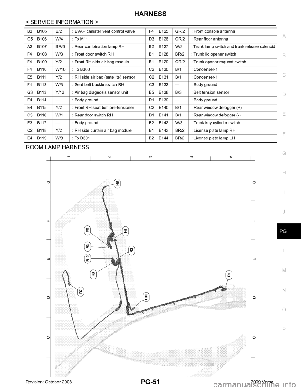
ROOM LAMP HARNESS
B3 B105 B/2 : EVAP canister vent control valve F4 B125 GR/2 : Front console antenna
G5 B106 W/4 : To M11 D3 B126 GR/2 : Rear floor antenna
A2 B107 BR/6 : Rear combination lamp RH B2 B127 W/3 : Trunk lamp switch and trunk release solenoid
F4 B108 W/3 : Front door switch RH B1 B128 BR/2 : Trunk lid opener switch
F4 B109 Y/2 : Front RH side air bag module B1 B129 GR/2 : Trunk opener request switch
F4 B110 W/10 : To B300 C2 B130 B/1 : Condenser-1
E5 B111 Y/2 : RH side air bag (satellite) sensor C2 B131 B/1 : Condenser-1
F4 B112 W/3 : Seat belt buckle switch RH C3 B132 — : Body ground
G3 B113 Y/12 : Air bag diagnosis sensor unit E5 B138 B/3 : Belt tension sensor
E4 B114 — : Body ground D1 B139 — : Body ground
E4 B115 Y/2 : Front RH seat belt pre-tensioner C2 B140 B/1 : Rear window defogger (+)
C3 B116 W/1 : Rear door switch RH D1 B141 B/1 : Rear window defogger (-)
E3 B117 — : Body ground B2 B142 W/3 : Trunk key cylinder switch
C2 B118 Y/2 : RH side curtain air bag module B1 B143 BR/2 : License plate lamp RH
E4 B119 W/8 : To D301 B2 B144 BR/2 : License plate lamp LH
Page 4035 of 4331

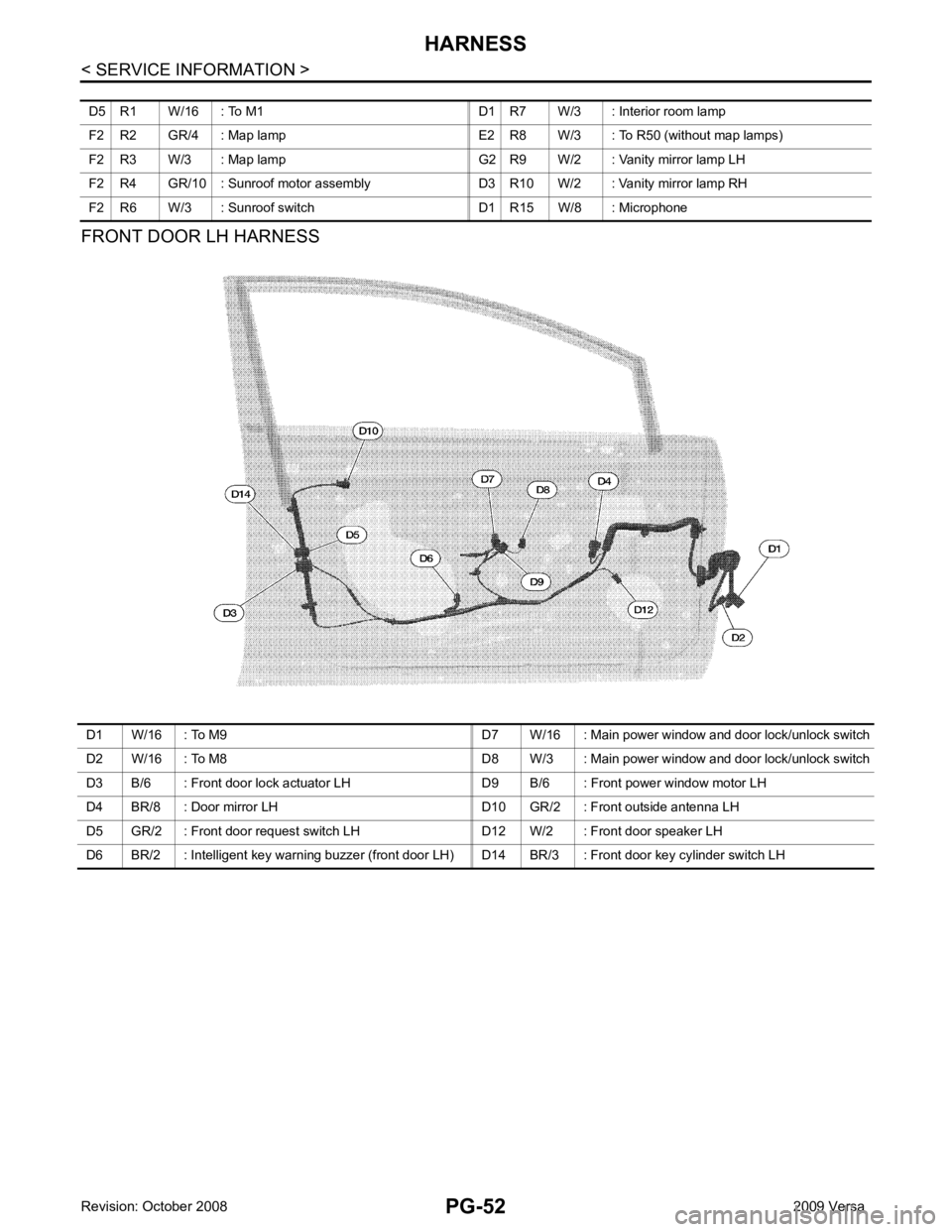
D1 W/16 : To M9 D7 W/16 : Main power window and door lock/unlock switch
D2 W/16 : To M8 D8 W/3 : Main power window and door lock/unlock switch
D3 B/6 : Front door lock actuator LH D9 B/6 : Front power window motor LH
D4 BR/8 : Door mirror LH D10 GR/2 : Front outside antenna LH
D5 GR/2 : Front door request switch LH D12 W/2 : Front door speaker LH
D6 BR/2 : Intelligent key warning buzzer (front door LH) D14 BR/3 : Front door key cylinder switch LH
Page 4065 of 4331

PS
N
O P
STEERING COLUMN
Removal and Installation INFOID:0000000004305933
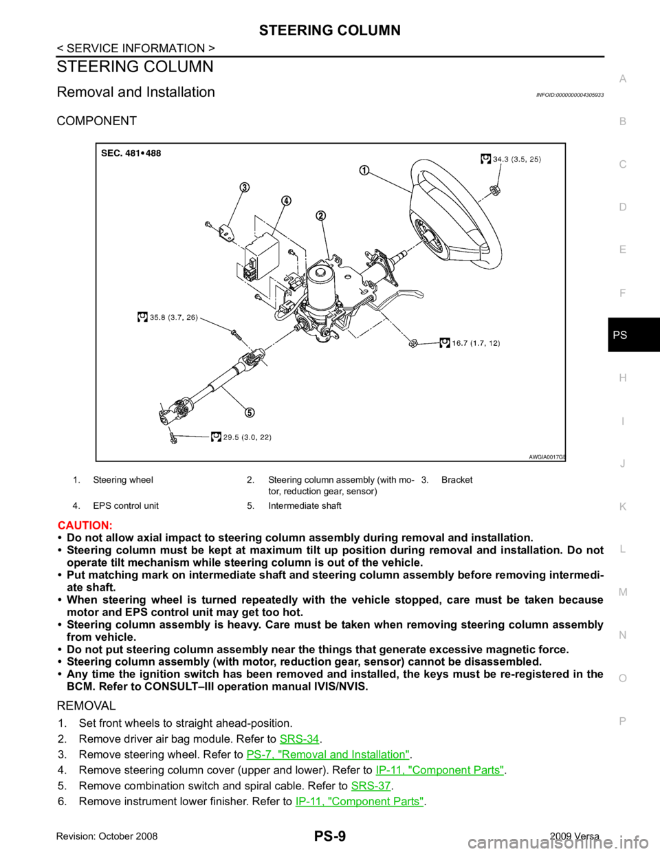
COMPONENT
CAUTION:
• Do not allow axial impact to steering colu mn assembly during removal and installation.
• Steering column must be kept at maximum tilt up position during removal and installation. Do not
operate tilt mechanism while steeri ng column is out of the vehicle.
• Put matching mark on intermediate shaft and st eering column assembly before removing intermedi-
ate shaft.
• When steering wheel is turned re peatedly with the vehicle stopped, care must be taken because
motor and EPS control unit may get too hot.
• Steering column assembly is heavy . Care must be taken when removing steering column assembly
from vehicle.
• Do not put steering column assem bly near the things that generate excessive magnetic force.
• Steering column assembly (with motor, reduc tion gear, sensor) cannot be disassembled.
• Any time the ignition switch h as been removed and installed, the keys must be re-registered in the
BCM. Refer to CONSULT–III ope ration manual IVIS/NVIS.
REMOVAL 1. Set front wheels to straight ahead-position.
2. Remove driver air bag module. Refer to SRS-34 .
3. Remove steering wheel. Refer to PS-7, " Removal and Installation " .
4. Remove steering column cover (upper and lower). Refer to IP-11, " Component Parts " .
5. Remove combination switch and spiral cable. Refer to SRS-37 .
6. Remove instrument lower finisher. Refer to IP-11, " Component Parts " .
1. Steering wheel 2. Steering column assembly (with mo-
tor, reduction gear, sensor)3. Bracket
4. EPS control unit 5. Intermediate shaft B
Page 4093 of 4331

Work Support " .
ANTI-PINCH FUNCTION
The CPU (central processing unit) of sunroof motor as sembly monitors the sunroof motor operation and the
sunroof position (fully-closed or other ) by the signals from sunroof motor.
When sunroof motor detects an interruption during the following slide close and tilt down operation, sunroof
switch controls the motor for open and the sunroof will oper ate until it reaches full up position (during tilt down
operation) or 125 mm (4.92 in) or more in an open direction (during slide close operation).
• close operation and tilt down when igniti on switch is in the ON position.
• close operation and tilt down during retained power operation.
INITIALIZATION FAILURE CONDITIONS
Initialization and teaching of system should be conducted if the following conditions exist:
• sunroof will only move in the UP/CLOSE direction, having a step by step motion
• sunroof does not have any auto operation.
INITIALIZATION PROCEDURE
If the sunroof does not close or open automatically, use the following procedure to return sunroof operation to
normal.
1. Press the switch to the UP/CLOSE position to tilt t he sunroof up fully. When the sunroof reaches the full tilt
up position it will back up a few millimeters and stop.
2. Release the UP/CLOSE switch.
3. Within 5 seconds of releasing the UP/CLOSE sw itch, press and hold the UP/CLOSE switch again. The
sunroof will move to the full open position and back to the closed position.
NOTE:
If the UP/CLOSE switch is released anytime during th is teaching process, all learned profile data will be dis-
carded and the procedure will have to be started over.
4. Release the UP/CLOSE switch. Do not disconnect power for at least two seconds. The sunroof is now ini-
tialized and taught.
Initializing procedure is complete. Confirm proper operation of the sunroof (slide open, slide closed, tilt up, tilt
down).
RE-TEACHING CONDITIONS
Re-teaching of system should be conducted if any of the following conditions exist:
• the sunroof is manually operated using the sunroof wrench with the battery discharged or disconnected.
• the sunroof is manually operated using the sunroof wrench with the key switch in the OFF position and
retained power timed out (after approximat ely 45 seconds or with a front door open).
• the sunroof motor assembly is replaced with a new one.
• the sunroof motor is removed from the sunroof assembly and operated before it is reinstalled.
Page 4193 of 4331

SRS
N
O P
OPERATION PROCEDURE
1. Connect both battery cables. NOTE:
Supply power using jumper cables if battery is discharged.
2. Use the Intelligent Key or mechanical key to turn the ignition switch to the ″ACC ″ position. At this time, the
steering lock will be released.
3. Disconnect both battery cables. The steering lock will remain released and the steering wheel can be
rotated.
4. Perform the necessary repair operation.
5. When the repair work is completed, return the ignition switch to the ″LOCK ″ position before connecting
the battery cables. (At this time, the steering lock mechanism will engage.)
6. Perform a self-diagnosis check of al l control units using CONSULT-III.
Occupant Classification System Precaution INFOID:0000000004307174
Replace control unit and passenger front seat cushion as an assembly.
Page 4215 of 4331

SRS
N
O P
2. Touch “TROUBLE DIAG RECORD”.
NOTE:
With “TROUBLE DIAG RECORD”, di agnosis results previously erased by a reset operation can be
displayed.
3. Diagnostic code is displayed on “TROUBLE DIAG RECORD”.
4. Touch “PRINT”.
5. Compare diagnostic codes to "CONSULT-III Diagnos tic Code Chart ("SELF-DIAG [PAST]" or "TROUBLE
DIAG RECORD")".
6. Touch “BACK” key of CONSULT- III until “SELECT SYSTEM” appears.
7. Turn ignition switch OFF, then turn off and disconnect CONSULT-III, and both battery cables.
8. Repair the system as outlined by the “Repair orde r” in “Intermittent Malfunction Diagnostic Code Chart”,
that corresponds to the self-diagnostic result. For r eplacement procedure of component parts, refer to the
Removal and Installation procedure for the appropriate component.
9. Go to "DIAGNOSTIC PROCEDURE 3", for final checking.
CONSULT-III Diagnostic Code Chart ("SELF-DI AG [PAST]" or "TROUBLE DIAG RECORD")
Diagnostic item Explanation Repair order
Recheck SRS at each replacement
NO DTC IS DETECTED When malfunction is
indicated by the “AIR
BAG” warning lamp in
User mode. • Low battery voltage (L
ess than 9V) • Go to "DIAGNOSTIC PROCEDURE
3" .
• Self-diagnostic result “SELF-DIAG [PAST]” (previously stored in the
memory) might not be erased after
repair.
• Intermittent malfunction has been detected in the past. • Go to "DIAGNOSTIC PROCEDURE
4" .
• Go to "DIAGNOSTIC PROCEDURE
5" .
• No malfunction is detected. —
DRIVER AIRBAG MODULE [OPEN]
[B1049] or [B1054] Driver air bag module circuit is open (including the spiral ca-
ble). 1. Visually check the wiring harness
connection.
2. Replace the harness if it has visi- ble damage.
3. Replace driver air bag module.
4. Replace the spiral cable.
5. Replace the air bag diagnosis
sensor unit.
6. Replace the related harness.
DRIVER AIRBAG MODULE
[VB-SHORT]
[B1050] or [B1055] Driver air bag module circuit is shorted to some power supply
circuit (including the spiral cable).
DRIVER AIRBAG MODULE [GND-SHORT]
[B1051] or [B1056] Driver air bag module circuit is shorted to ground (including
the spiral cable).
DRIVER AIRBAG MODULE [SHORT]
[B1052] or [B1057] Driver air bag module circuits are shorted to each other.
ASSIST A/B MODULE [OPEN]
[B1065] or [B1070] Front passenger air bag module circuit is open. 1. Visually check the wiring harness
connection.
2. Replace the harness if it has visi-
ble damage.
3. Replace front passenger air bag module.
4. Replace the air bag diagnosis sensor unit.
5. Replace the related harness.
ASSIST A/B MODULE
[VB-SHORT]
[B1066] or [B1071] Front passenger air bag module circuit is shorted to some
power supply circuit.
ASSIST A/B MODULE [GND-SHORT]
[B1067] or [B1072] Front passenger air bag module circuit is shorted to ground.
ASSIST A/B MODULE [SHORT]
[B1068] or [B1073] Front passenger air bag module circuits are shorted to each
other.