2009 NISSAN LATIO coolant temperature
[x] Cancel search: coolant temperaturePage 1724 of 4331

DTC Logic " .
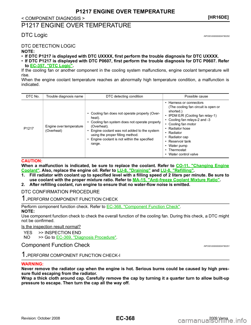
If the cooling fan or another component in the coo ling system malfunctions, engine coolant temperature will
rise.
When the engine coolant temperature reaches an abnorma lly high temperature condition, a malfunction is
indicated.
CAUTION:
When a malfunction is indicated, be su re to replace the coolant. Refer to CO-11, " Changing Engine
Coolant " . Also, replace the engine oil. Refer to
LU-8, " Draining " and
LU-8, " Refilling " .
1. Fill radiator with coolant up to specified level with a filling speed of 2 liters per minute. Be sure to
use coolant with the proper mixture ratio. Refer to MA-15, " Anti-freeze Coolant Mixture Ratio " .
2. After refilling coolant, run engine to en sure that no water-flow noise is emitted.
DTC CONFIRMATION PROCEDURE Component Function Check " .
NOTE:
Use component function check to check the overall functi on of the cooling fan. During this check, a DTC might
not be confirmed.
Is the inspection result normal? YES >> INSPECTION END
NO >> Go to EC-369, " Diagnosis Procedure " .
Component Function Check INFOID:0000000004780251
Page 1726 of 4331

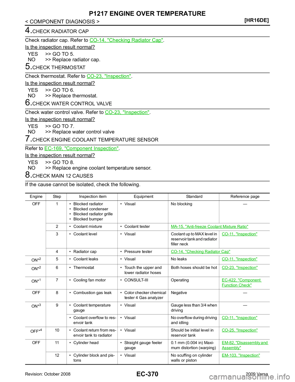
Checking Radiator Cap " .
Is the inspection result normal? YES >> GO TO 5.
NO >> Replace radiator cap. Inspection " .
Is the inspection result normal? YES >> GO TO 6.
NO >> Replace thermostat. Inspection " .
Is the inspection result normal? YES >> GO TO 7.
NO >> Replace water control valve Component Inspection " .
Is the inspection result normal? YES >> GO TO 8.
NO >> Replace engine coolant temperature sensor. Anti-freeze Coolant Mixture Ratio "
3 • Coolant level • Visual Coolant up to MAX level in
reservoir tank and radiator
filler neck CO-11, " Inspection "
4 • Radiator cap • Pressure tester
CO-14, " Checking Radiator Cap "
ON*
2
5 • Coolant leaks • Visual No leaks CO-11, " Inspection "
ON*
2
6 • Thermostat • Touch the upper and
lower radiator hosesBoth hoses should be hot
CO-23, " Inspection "
ON*
1
7 • Cooling fan motor • CONSULT-III Operating EC-422, " Component
Function Check "
OFF 8 • Combustion gas leak • Color checker chemical
tester 4 Gas analyzerNegative —
ON* 3
9 • Coolant temperature
gauge • Visual Gauge less than 3/4 when
driving —
• Coolant overflow to res- ervoir tank • Visual No overflow during driving
and idling CO-11, " Inspection "
OFF*
4
10 • Coolant return from res-
ervoir tank to radiator • Visual Should be initial level in
reservoir tank CO-25, " Inspection "
OFF 11 • Cylinder head • Straight gauge feeler
gauge0.1 mm (0.004 in) Maxi-
mum distortion (warping) EM-82, " Disassembly and
Assembly "
12 • Cylinder block and pis-
tons • Visual No scuffing on cylinder
walls or piston EM-103, " Inspection "
Page 1819 of 4331

EC
NP
O
*: Accelerator pedal position sensor 2 signal and throttle position sensor 2 signal are converted by ECM internally. Thus, they
differ from
ECM terminals voltage signal.
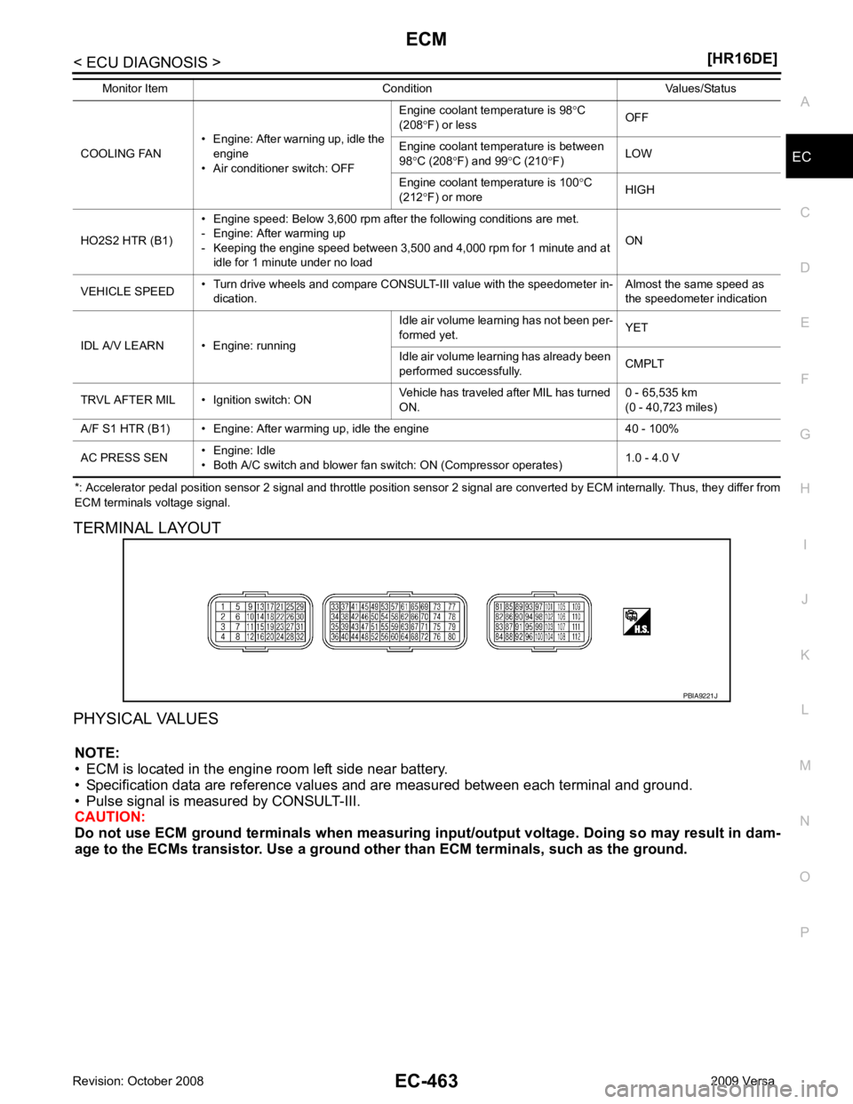
TERMINAL LAYOUT
PHYSICAL VALUES NOTE:
• ECM is located in the engine room left side near battery.
• Specification data are reference values and are measured between each terminal and ground.
• Pulse signal is measured by CONSULT-III.
CAUTION:
Do not use ECM ground terminals wh en measuring input/output voltage. Doing so may result in dam-
age to the ECMs transistor. Use a ground ot her than ECM terminals, such as the ground.
COOLING FAN
• Engine: After warning up, idle the
engine
• Air conditioner switch: OFF Engine coolant temperature is 98
°C
(208 °F) or less OFF
Engine coolant temperature is between
98 °C (208 °F) and 99 °C (210 °F) LOW
Engine coolant temperature is 100 °C
(212 °F) or more HIGH
HO2S2 HTR (B1) • Engine speed: Below 3,600 rpm after the following conditions are met.
- Engine: After warming up
- Keeping the engine speed between 3,500 and 4,000 rpm for 1 minute and at idle for 1 minute under no load ON
VEHICLE SPEED • Turn drive wheels and compare CONSULT-III value with the speedometer in-
dication. Almost the same speed as
the speedometer indication
IDL A/V LEARN • Engine: running Idle air volume learning has not been per-
formed yet. YET
Idle air volume learning has already been
performed successfully. CMPLT
TRVL AFTER MIL • Ignition switch: ON Vehicle has traveled after MIL has turned
ON. 0 - 65,535 km
(0 - 40,723 miles)
A/F S1 HTR (B1) • Engine: After warming up, idle the engine 40 - 100%
AC PRESS SEN • Engine: Idle
• Both A/C switch and blower fan switch: ON (Compressor operates) 1.0 - 4.0 V
Monitor Item Condition Values/Status
Page 1823 of 4331
![NISSAN LATIO 2009 Service Repair Manual EC
NP
O
41 GR Refrigerant pressure sensor
[Engine is running]
• Warm-up condition
• Both A/C switch and blower fan switch: ON
(Compressor operates.) 1.0 - 4.0 V
42 V EVAP control system pres-
sur NISSAN LATIO 2009 Service Repair Manual EC
NP
O
41 GR Refrigerant pressure sensor
[Engine is running]
• Warm-up condition
• Both A/C switch and blower fan switch: ON
(Compressor operates.) 1.0 - 4.0 V
42 V EVAP control system pres-
sur](/manual-img/5/57359/w960_57359-1822.png)
EC
NP
O
41 GR Refrigerant pressure sensor
[Engine is running]
• Warm-up condition
• Both A/C switch and blower fan switch: ON
(Compressor operates.) 1.0 - 4.0 V
42 V EVAP control system pres-
sure sensor [Ignition switch: ON]
Approximately 1.8 - 4.8 V
43 P Fuel tank temperature sen-
sor [Engine is running] Approximately 0 - 4.8 V
Output voltage varies with fuel
tank temperature
44 B Sensor ground
(Engine coolant temperature
sensor) [Engine is running]
• Warm-up condition
• Idle speed Approximately 0 V
45 G Mass air flow sensor [Engine is running]
• Warm-up condition
• Idle speed 0.9 - 1.3 V
[Engine is running]
• Warm-up condition
• Engine speed: 2,500 rpm 1.4 - 1.9 V
46 V Intake air temperature
sensor [Engine is running] Approximately 0 - 4.8 V
Output voltage varies with intake
air temperature.
48 BR Sensor ground
(Refrigerant pressure sen-
sor) [Engine is running]
• Warm-up condition
• Idle speed Approximately 0 V
49 W A/F sensor 1 [Engine is running]
• Warm-up condition
• Engine speed: 2,000 rpm Approximately 1.8 V
Output voltage varies with air fuel
ratio.
50 W Heated oxygen sensor 2 [Engine is running]
• Revving engine from idle to 3,000 rpm quickly after the following conditions are
met.
- Engine: After warming up
- Keeping the engine speed between 3,500
and 4,000 rpm for 1 minute and at idle for 1
minute under no load. 0 - 1.0 V
51 O Sensor ground
(EVAP control system pres-
sure sensor) [Engine is running]
• Warm-up condition
• Idle speed Approximately 0 V
52 LG Sensor ground
(Mass air flow sensor) [Engine is running]
• Warm-up condition
• Idle speed Approximately 0 V
53 B A/F sensor 1 [Ignition switch: ON]Approximately 2.2 V
55 O Sensor ground
(Intake air temperature sen-
sor) [Engine is running]
• Warm-up condition
• Idle speed Approximately 0 V
59 O Sensor ground
(Heated oxygen sensor 2) [Engine is running]
• Warm-up condition
• Idle speed Approximately 0 V
TERMI-
NAL
NO. WIRE
COLOR ITEM CONDITION DATA (DC Voltage)
Page 1829 of 4331

EC
NP
O
DTC RELATED ITEM
Detected items
Engine operating condition in
fail-safe mode Remarks
Malfunction indicator
lamp circuit Engine speed will not rise
more than 2,500 rpm due to
the fuel cut When there is an open circuit on MIL circuit, the ECM cannot warn the driver by
lighting up MIL when there is malfunction on engine control system.
Therefore, when electrical controlled throttle and part of ECM related diagnoses
are continuously detected as NG for 5 trips, ECM warns the driver that engine
control system malfunctions and MIL circuit is open by means of operating fail-
safe function.
The fail-safe function also operates when above diagnoses except MIL circuit
are detected and demands the driver to repair the malfunction. DTC No. Detected items Engine operating condition in fail-safe mode
P0011 Intake valve timing control The signal is not energized to the intake valve timing control solenoid valve and the valve control does not function.
P0102
P0103 Mass air flow sensor circuit Engine speed will not rise more than 2,400 rpm due to the fuel cut.
P0117
P0118 Engine coolant tempera-
ture sensor circuit Engine coolant temperature will be determined by ECM based on the following condition.
CONSULT-III displays the engine coolant temperature decided by ECM.
Condition Engine coolant temperature decided
(CONSULT-III display)
Just as ignition switch is turned ON
or START 40
°C (104 °F)
More than approx. 4 minutes after
engine starting 80
°C (176 °F)
Except as shown above 40 - 80
°C (104 - 176 °F)
(Depends on the time)
When the fail-safe system for engine coolant temperature sensor is activated, the cooling
fan operates while engine is running.
P0122
P0123
P0222
P0223
P2135 Throttle position sensor The ECM controls the electric throttle control actuator in regulating the throttle opening in
order for the idle position to be within +10 degrees.
The ECM regulates the opening speed of the throttle valve to be slower than the normal
condition.
So, the acceleration will be poor.
P0643 Sensor power supply ECM stops the electric throttle control actuator control, throttle valve is maintained at a fixed opening (approx. 5 degrees) by the return spring.
P0605 ECM (When ECM calculation function is malfunctioning:) ECM stops the electric throttle control actuator control, throttle valve is maintained at a
fixed opening (approx. 5 degrees) by the return spring.
P1805 Brake switch ECM controls the electric throttle control actuator by regulating the throttle opening to a small range.
Therefore, acceleration will be poor.
Vehicle condition Driving condition
When engine is idling Normal
When accelerating Poor acceleration
P2100
P2103 Throttle control motor relay ECM stops the electric throttle control actuator control, throttle valve is maintained at a
fixed opening (approx. 5 degrees) by the return spring.
P2101 Electric th rottle control
function ECM stops the electric throttle control actuator control, throttle valve is maintained at a
fixed opening (approx. 5 degrees) by the return spring.
P2118 Throttle control motor ECM stops the electric throttle control actuator control, throttle valve is maintained at a fixed opening (approx. 5 degrees) by the return spring.
Page 1830 of 4331

Priority Detected items (DTC)
1 • U0101 U0140 U1001 CAN communication line • P0101 P0102 P0103 Mass air flow sensor
• P0112 P0113 P0127 Intake air temperature sensor
• P0116 P0117 P0118 P0125 Engine coolant temperature sensor
• P0122 P0123 P0222 P0223 P1225 P1226 P2135 Throttle position sensor
• P0128 Thermostat function
• P0181 P0182 P0183 Fuel tank temperature sensor
• P0327 P0328 Knock sensor
• P0335 Crankshaft position sensor (POS)
• P0340 Camshaft posi tion sensor (PHASE)
• P0460 P0461 P0462 P0463 Fuel level sensor
• P0500 Vehicle speed sensor
• P0605 P0607 ECM
• P0643 Sensor power supply
• P0705 P0850 Park/neutral position (PNP) switch
• P1610 - P1615 NATS
• P2122 P2123 P2127 P2128 P2138 Accelerator pedal position sensor
Page 1843 of 4331

EC
NP
O
SYMPTOM DIAGNOSIS
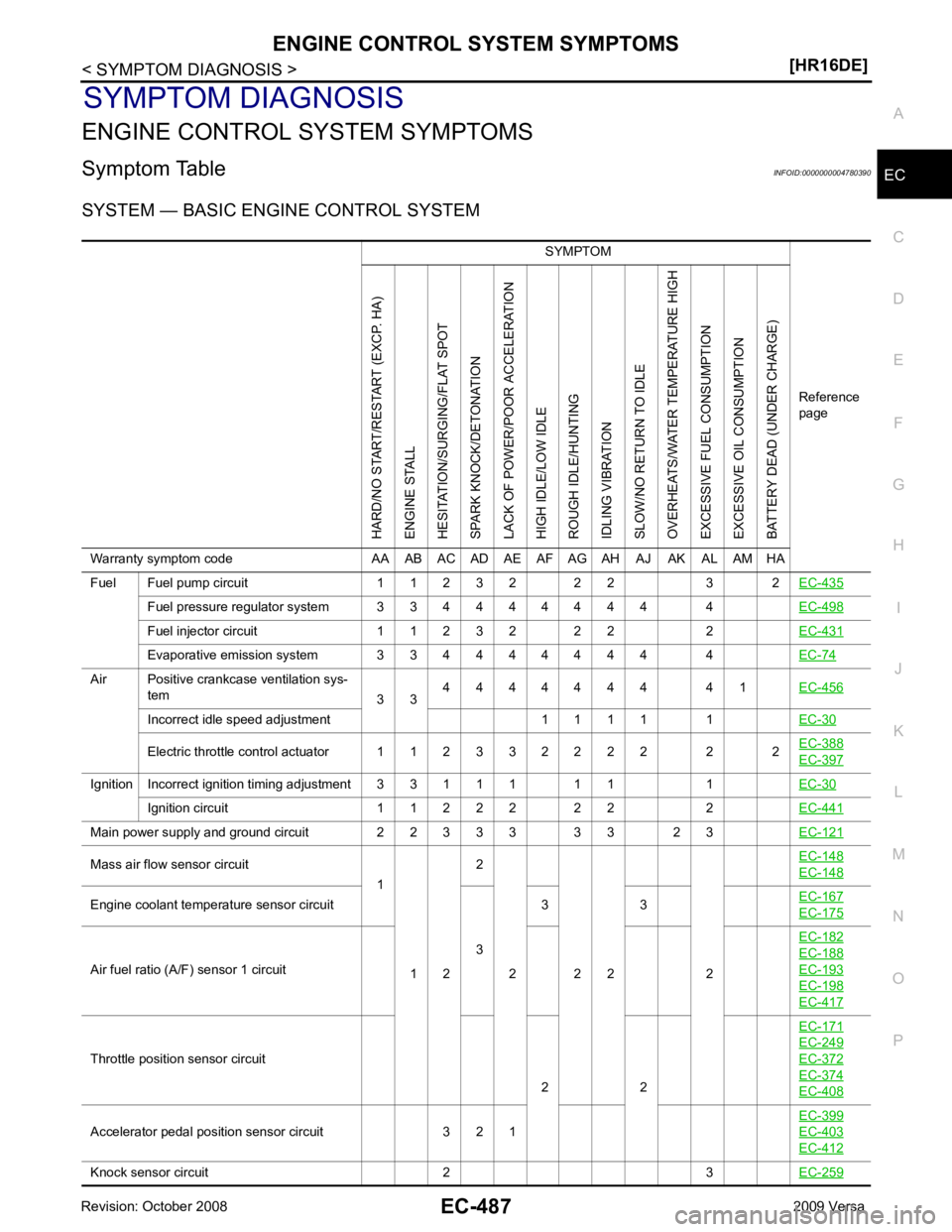
ENGINE CONTROL SYSTEM SYMPTOMS
Symptom Table INFOID:0000000004780390
SYSTEM — BASIC ENGINE CONTROL SYSTEM SYMPTOM
Reference
pageHARD/NO START/RESTART (EXCP. HA)
ENGINE STALL
HESITATION/SURGING/FLAT SPOT
SPARK KNOCK/DETONATION
LACK OF POWER/POOR ACCELERATION
HIGH IDLE/LOW IDLE
ROUGH IDLE/HUNTING
IDLING VIBRATION
SLOW/NO RETURN TO IDLE
OVERHEATS/WATER TEMPERATURE HIGH
EXCESSIVE FUEL CONSUMPTION
EXCESSIVE OIL CONSUMPTION
BATTERY DEAD (UNDER CHARGE)
Warranty symptom code AA AB AC AD AE AF AG AH AJ AK AL AM HA
Fuel Fuel pump circuit 1 1 2 3 2 2 2 3 2 EC-435Fuel pressure regulator system 3 3 4 4 4 4 4 4 4 4
EC-498Fuel injector circuit 1 1 2 3 2 2 2 2
EC-431Evaporative emission system 3 3 4 4 4 4 4 4 4 4
EC-74Air Positive crankcase ventilation sys-
tem 3 34 4 4 4 4 4 4 4 1
EC-456Incorrect idle speed adjustment 1 1 1 1 1
EC-30Electric throttle control actuator 1 1 2 3 3 2 2 2 2 2 2
EC-388 EC-397
Ignition Incorrect ignition timing adjustment 3 3 1 1 1 1 1 1
EC-30Ignition circuit 1 1 2 2 2 2 2 2
EC-441Main power supply and ground circuit 2 2 3 3 3 3 3 2 3
EC-121Mass air flow sensor circuit
1
1 2 2
2 2 2 2 EC-148 EC-148
Engine coolant temperature sensor circuit
33 3
EC-167 EC-175
Air fuel ratio (A/F) sensor 1 circuit
EC-182 EC-188
EC-193
EC-198
EC-417
Throttle position sensor circuit
2 2EC-171 EC-249
EC-372
EC-374
EC-408
Accelerator pedal position sensor circuit 3 2 1
EC-399 EC-403
EC-412
Knock sensor circuit 2 3
EC-259
Page 1846 of 4331

Camshaft
EM-58Intake valve timing control
EM-49Intake valve
3EM-82 Exhaust valve
Exhaust Exhaust manifold/Tube/Muf- fler/Gasket 5 5 5 5 5 5 5 5 EM-31 EX-4
Three way catalyst
Lubrica-
tion Oil pan/Oil strainer/Oil pump/ Oil filter/Oil gallery/Oil cooler 5 5 5 5 5 5 5 5 EM-39 EM-42
LU-7
LU-9
Oil level (Low)/Filthy oil
LU-7Cooling Radiator/Hose/Radiator filler
cap
5 5 5 5 5 5 5 4 5 CO-14 CO-14
Thermostat 5
CO-23Water pump
CO-21Water gallery
CO-9Cooling fan
5CO-19Coolant level (Low)/Contami-
nated coolant CO-9NVIS (NISSAN Vehicle Immobilizer Sys-
tem — NATS) 1 1
BL-257 SYMPTOM
Reference pageHARD/NO START/RESTART (EXCP. HA)
ENGINE STALL
HESITATION/SURGING/FLAT SPOT
SPARK KNOCK/DETONATION
LACK OF POWER/POOR ACCELERATION
HIGH IDLE/LOW IDLE
ROUGH IDLE/HUNTING
IDLING VIBRATION
SLOW/NO RETURN TO IDLE
OVERHEATS/WATER TEMPERATURE HIGH
EXCESSIVE FUEL CONSUMPTION
EXCESSIVE OIL CONSUMPTION
BATTERY DEAD (UNDER CHARGE)
Warranty symptom code A AAB AC AD AE AF AG AH AJ AK AL AM HA