2009 NISSAN LATIO light
[x] Cancel search: lightPage 845 of 4331

BRC
N
O P
SYSTEM DESCRIPTION
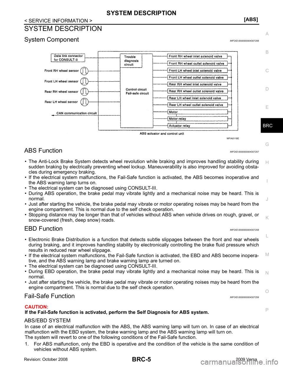
System Component INFOID:0000000004307256
ABS Function INFOID:0000000004307257
• The Anti-Lock Brake System detects wheel revolution while braking and improves handling stability during sudden braking by electrically preventing wheel lockup. Maneuverability is also improved for avoiding obsta-
cles during emergency braking.
• If the electrical system malfunctions, the Fail-Safe function is activated, the ABS becomes inoperative and
the ABS warning lamp turns on.
• The electrical system can be diagnosed using CONSULT-III.
• During ABS operation, the brake pedal may vibrate lightly and a mechanical noise may be heard. This is
normal.
• Just after starting the vehicle, the brake pedal may vibrate or motor operating noises may be heard from the
engine compartment. This is normal due to the self check operation.
• Stopping distance may be longer than that of vehicles without ABS when vehicle drives on rough, gravel, or
snow-covered (fresh, deep snow) roads.
EBD Function INFOID:0000000004307258
• Electronic Brake Distribution is a function that detec ts subtle slippages between the front and rear wheels
during braking, and it improves handling stability by elec tronically controlling the brake fluid pressure which
results in reduced rear wheel slippage.
• If the electrical system malfunctions, the Fail-Safe function is activated, the EBD and ABS become inopera-
tive, and the ABS warning lamp and brake warning lamp are turned on.
• The electrical system can be diagnosed using CONSULT-III.
• During EBD operation, the brake pedal may vibrate lightly and a mechanical noise may be heard. This is
normal.
• Just after starting the vehicle, the brake pedal may vibrate or motor operating noises may be heard from the
engine compartment. This is normal due to the self check operation.
Fail-Safe Function INFOID:0000000004307259
CAUTION:
If the Fail-Safe function is activated, perform the Self Diagnosis for ABS system.
ABS/EBD SYSTEM In case of an electrical malfunction with the ABS, the ABS warning lamp wi ll turn on. In case of an electrical
malfunction with the EBD system, the brake warni ng lamp and the ABS warning lamp will turn on.
The system will revert to one of the follo wing conditions of the Fail-Safe function.
1. For ABS malfunction, only the EBD is operative and t he condition of the vehicle is the same condition of
vehicles without ABS system.
Page 906 of 4331

Recommended Chemical Product and Sealant " .
2. If disconnected, reattach the upper radiator hose at the engine side.
3. Set the vehicle heater controls to the full HOT and heat er ON position. Turn the vehicle ignition ON with
the engine OFF as necessary to activate the heater mode.
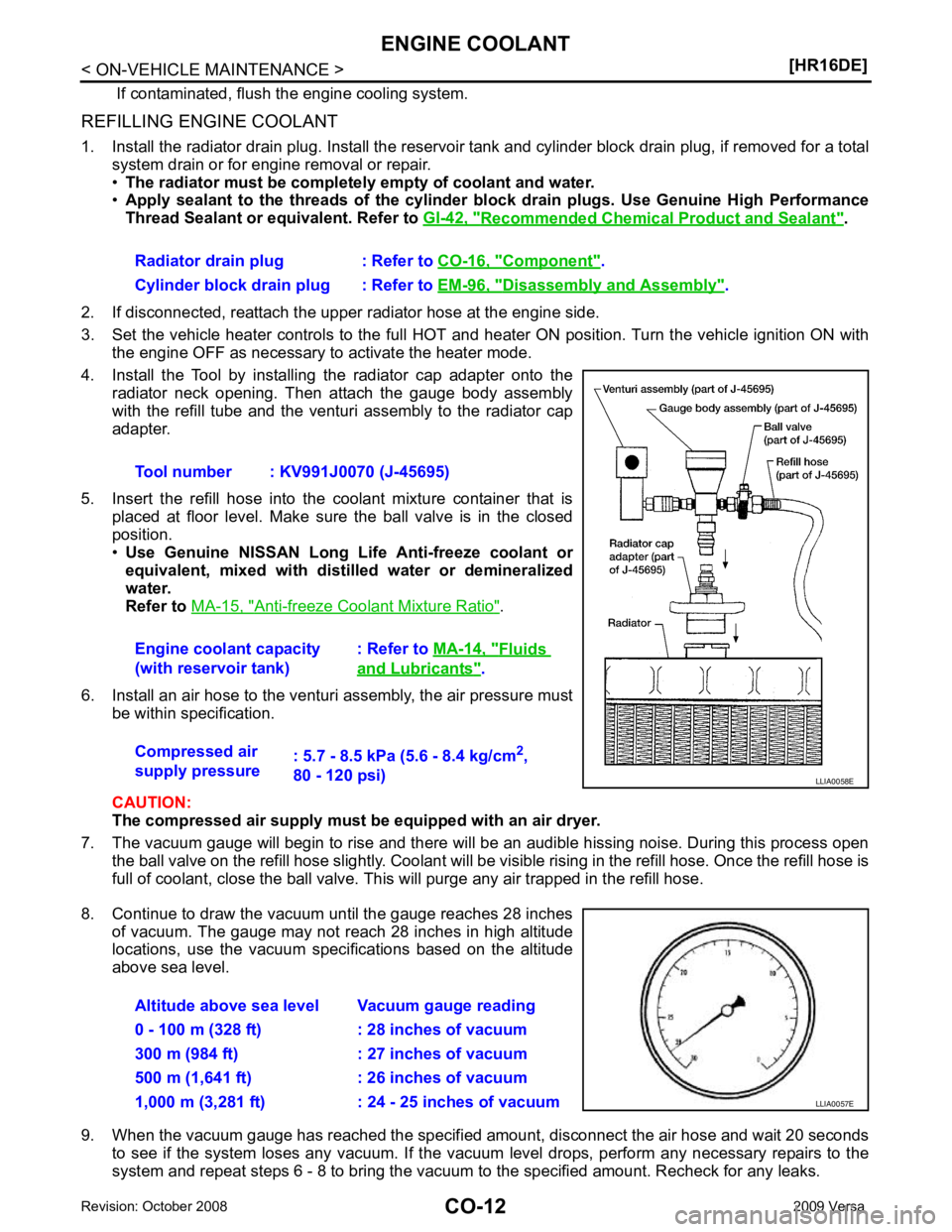
4. Install the Tool by installing the radiator cap adapter onto the radiator neck opening. Then attach the gauge body assembly
with the refill tube and the venturi assembly to the radiator cap
adapter.
5. Insert the refill hose into the coolant mixture container that is placed at floor level. Make sure the ball valve is in the closed
position.
• Use Genuine NISSAN Long Life Anti-freeze coolant or
equivalent, mixed with distil led water or demineralized
water.
Refer to MA-15, " Anti-freeze Coolant Mixture Ratio " .
6. Install an air hose to the venturi assembly, the air pressure must be within specification.
CAUTION:
The compressed air supply must be equipped with an air dryer.
7. The vacuum gauge will begin to rise and there will be an audible hissing noise. During this process open the ball valve on the refill hose slightly. Coolant will be vi sible rising in the refill hose. Once the refill hose is
full of coolant, close the ball valve. This will purge any air trapped in the refill hose.
8. Continue to draw the vacuum until the gauge reaches 28 inches of vacuum. The gauge may not reach 28 inches in high altitude
locations, use the vacuum specifications based on the altitude
above sea level.
9. When the vacuum gauge has reached the specifi ed amount, disconnect the air hose and wait 20 seconds
to see if the system loses any vacuum. If the vacuum level drops, perform any necessary repairs to the
system and repeat steps 6 - 8 to bring the vacuum to the specified amount. Recheck for any leaks.
Radiator drain plug : Refer to
CO-16, " Component " .
Cylinder block drain plug : Refer to EM-96, " Disassembly and Assembly " .
Tool number : KV991J0070 (J-45695)
Engine coolant capacity
(with reservoir tank) : Refer to
MA-14, " Fluids
and Lubricants " .
Compressed air
supply pressure : 5.7 - 8.5 kPa (5.6 - 8.4 kg/cm
2
,
80 - 120 psi)
Page 923 of 4331
![NISSAN LATIO 2009 Service Repair Manual PRECAUTIONS
CO-29
< SERVICE INFORMATION >
[MR18DE] C
D E
F
G H
I
J
K L
M A CO
NP
O
Precaution for Liquid Gasket
INFOID:0000000004305229
REMOVAL OF LIQUID GASKET SEALING • After removing nuts and bol NISSAN LATIO 2009 Service Repair Manual PRECAUTIONS
CO-29
< SERVICE INFORMATION >
[MR18DE] C
D E
F
G H
I
J
K L
M A CO
NP
O
Precaution for Liquid Gasket
INFOID:0000000004305229
REMOVAL OF LIQUID GASKET SEALING • After removing nuts and bol](/manual-img/5/57359/w960_57359-922.png)
PRECAUTIONS
CO-29
< SERVICE INFORMATION >
[MR18DE] C
D E
F
G H
I
J
K L
M A CO
NP
O
Precaution for Liquid Gasket
INFOID:0000000004305229
REMOVAL OF LIQUID GASKET SEALING • After removing nuts and bolts, separate the mating surface, using Tool and remove old liquid gasket sealing.
CAUTION:
Be careful not to damage the mating surfaces.
• Tap Tool to insert it (1), and then slide it by tapping on the side (2)
as shown.
• In areas where Tool is difficult to use, use plastic hammer to lightly
tap the parts, to remove it.
CAUTION:
If for some unavoidable reason suitable tool such as screw-
driver is used, be careful not to damage the mating surfaces.
LIQUID GASKET APPLICATION PROCEDURE 1. Remove old liquid gasket adhering to the liquid gasket applica- tion surface and the mating surface, using scraper.
• Remove liquid gasket completely from the groove of the liquid gasket application surface, bolts, and bolt holes.
2. Thoroughly clean the mating surfaces and remove adhering moisture, grease and foreign materials.
3. Attach liquid gasket tube to Tool.
Use Genuine RTV Silicone Seal ant or equivalent. Refer to GI-42, " Recommended Chemical Prod-
uct and Sealant " .
4. Apply liquid gasket without breaks to the spec ified location with the specified dimensions.
• If there is a groove for the liquid gasket application, apply liquid gasket to the groove.
• As for the bolt holes, normally apply liquid gasket inside the holes. Occasionally, it should be applied outside the holes.
Make sure to read the text of service manual.
• Within five minutes of liquid gasket application, install the mat-
ing component.
• If liquid gasket protrudes, wipe it off immediately.
• Do not retighten nuts or bolts after the installation.
• After 30 minutes or more have passed from the installation, fill engine oil and engine coolant.
CAUTION:
If there are specific instructions in this manual, observe them.
Tool number : KV10111100 (J-37228)
WBIA0566E
Tool number : WS39930000 ( — )
PBIC0003E
WBIA0567E
SEM159F
Page 930 of 4331
![NISSAN LATIO 2009 Service Repair Manual CO-36< SERVICE INFORMATION >
[MR18DE]
ENGINE COOLANT
REFILLING ENGINE COOLANT
1. Install the radiator drain plug. Install the reservoir tank and cylinder block drain plug, if removed for a total
syst NISSAN LATIO 2009 Service Repair Manual CO-36< SERVICE INFORMATION >
[MR18DE]
ENGINE COOLANT
REFILLING ENGINE COOLANT
1. Install the radiator drain plug. Install the reservoir tank and cylinder block drain plug, if removed for a total
syst](/manual-img/5/57359/w960_57359-929.png)
CO-36< SERVICE INFORMATION >
[MR18DE]
ENGINE COOLANT
REFILLING ENGINE COOLANT
1. Install the radiator drain plug. Install the reservoir tank and cylinder block drain plug, if removed for a total
system drain or for engine removal or repair.
• The radiator must be complete ly empty of coolant and water.
• Apply sealant to the threads of the cylinder bl ock drain plugs. Use Genuine High Performance
Thread Sealant or equivalent. Refer to GI-42, " Recommended Chemical Product and Sealant " .
2. If disconnected, reattach the upper radiator hose at the engine side.
3. Set the vehicle heater controls to the full HOT and heat er ON position. Turn the vehicle ignition ON with
the engine OFF as necessary to activate the heater mode.
4. Install the Tool by installing the radiator cap adapter onto the radiator neck opening. Then attach the gauge body assembly
with the refill tube and the venturi assembly to the radiator cap
adapter.
5. Insert the refill hose into the coolant mixture container that is placed at floor level. Make sure the ball valve is in the closed
position.
• Use Genuine NISSAN Long Life Anti-freeze coolant or
equivalent, mixed with distil led water or demineralized
water.
Refer to MA-15, " Anti-freeze Coolant Mixture Ratio " .
6. Install an air hose to the venturi assembly, the air pressure must be within specification.
CAUTION:
The compressed air supply must be equipped with an air dryer.
7. The vacuum gauge will begin to rise and there will be an audible hissing noise. During this process open the ball valve on the refill hose slightly. Coolant will be vi sible rising in the refill hose. Once the refill hose is
full of coolant, close the ball valve. This will purge any air trapped in the refill hose.
8. Continue to draw the vacuum until the gauge reaches 28 inches of vacuum. The gauge may not reach 28 inches in high altitude
locations, use the vacuum specifications based on the altitude
above sea level.
9. When the vacuum gauge has reached the specifi ed amount, disconnect the air hose and wait 20 seconds
to see if the system loses any vacuum. If the vacuum level drops, perform any necessary repairs to the
system and repeat steps 6 - 8 to bring the vacuum to the specified amount. Recheck for any leaks.
Radiator drain plug : Refer to
CO-38, " Component " .
Cylinder block drain plug : Refer to EM-200, " Disassembly and Assembly " .
Tool number : KV991J0070 (J-45695)
Engine coolant capacity
(with reservoir tank) : Refer to
MA-14, " Fluids
and Lubricants " .
Compressed air
supply pressure : 5.7 - 8.5 kPa (5.6 - 8.4 kg/cm
2
,
80 - 120 psi) LLIA0058E
Altitude above sea level Vacuum gauge reading
0 - 100 m (328 ft) : 28 inches of vacuum
300 m (984 ft) : 27 inches of vacuum
500 m (1,641 ft) : 26 inches of vacuum
1,000 m (3,281 ft) : 24 - 25 inches of vacuum LLIA0057E
Page 957 of 4331

CVT
N
O P
Do not start engine.
6. Select “SELF-DIAG RESULTS”.
7. Shift the selector lever to “R” position.
8. Depress slightly the accelerator pedal (Pedal angle: 2/8) while depressing the brake pedal.
9. Perform “ERASE”.
10. Shift the selector lever to “R” position afte r replacing TCM. Turn the ignition switch OFF.
11. Wait approximately 10 minutes after turning the ignition switch OFF.
12. Turn the ignition switch ON while shifting the selector lever to “R” position. CAUTION:
Do not start engine.
13. Select “CALIBRATION DATA”.
14. Check that the value on “CALIBRATION DATA” is same as the data after erasing "Calibration Data". • Restart the procedure from step 3 if the values are not same.
15. Shift the selector lever to “P” position.
16. Check that the shift position indicator in the combi nation meter turns ON (It indicates approximately 1 or 2
seconds after shifting the selector lever to “P” position.)
• Check the following items if the shift position indicato r does not turn ON. Repair or replace the shift posi-
tion indicator if necessary.
- The harness between TCM and ROM ASSY in the transaxle assembly is open or short.
- Cable disconnected, loosen, or bent from the connector housing.
- Power supply and ground of TCM. Refer to CVT-125, " Description " .
PATTERN C 1. Replace the transaxle assembly first, and then replace TCM.
2. Perform the service of “PATTERN A”. (Perform the service of “Pattern B” if TCM is replaced first.)
Removal and Installation Proc edure for CVT Unit Connector INFOID:0000000004666857
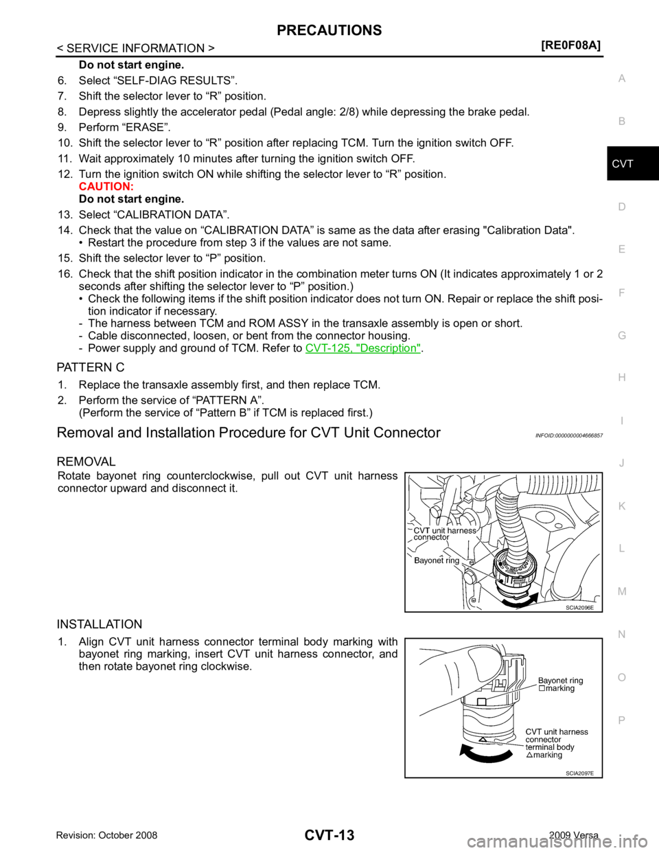
REMOVAL Rotate bayonet ring counterclockwise, pull out CVT unit harness
connector upward and disconnect it.
INSTALLATION 1. Align CVT unit harness connector terminal body marking with bayonet ring marking, insert CVT unit harness connector, and
then rotate bayonet ring clockwise.
Page 976 of 4331
![NISSAN LATIO 2009 Service Repair Manual CVT-32< SERVICE INFORMATION >
[RE0F08A]
ON BOARD DIAGNOSTIC (OBD) SYSTEM
The MIL is located on the instrument panel.
1. The MIL will light up when the ignition switch is turned ON with- out the engine NISSAN LATIO 2009 Service Repair Manual CVT-32< SERVICE INFORMATION >
[RE0F08A]
ON BOARD DIAGNOSTIC (OBD) SYSTEM
The MIL is located on the instrument panel.
1. The MIL will light up when the ignition switch is turned ON with- out the engine](/manual-img/5/57359/w960_57359-975.png)
CVT-32< SERVICE INFORMATION >
[RE0F08A]
ON BOARD DIAGNOSTIC (OBD) SYSTEM
The MIL is located on the instrument panel.
1. The MIL will light up when the ignition switch is turned ON with- out the engine running. This is a bulb check.
• If the MIL does not light up, refer to DI-20, " Schematic " , or see
EC-1010, " Wiring Diagram " .
2. When the engine is started, the MIL should go off. If the MIL remains on, the on board diagnostic system has
detected an engine system malfunction. SEF217U
Page 1117 of 4331
![NISSAN LATIO 2009 Service Repair Manual SHIFT CONTROL SYSTEM
CVT-173
< SERVICE INFORMATION >
[RE0F08A] D
E
F
G H
I
J
K L
M A
B CVT
N
O P
7. Remove the plate (1) from the control device assembly.
: Vehicle front
8. Remove the lock plate (1) NISSAN LATIO 2009 Service Repair Manual SHIFT CONTROL SYSTEM
CVT-173
< SERVICE INFORMATION >
[RE0F08A] D
E
F
G H
I
J
K L
M A
B CVT
N
O P
7. Remove the plate (1) from the control device assembly.
: Vehicle front
8. Remove the lock plate (1)](/manual-img/5/57359/w960_57359-1116.png)
SHIFT CONTROL SYSTEM
CVT-173
< SERVICE INFORMATION >
[RE0F08A] D
E
F
G H
I
J
K L
M A
B CVT
N
O P
7. Remove the plate (1) from the control device assembly.
: Vehicle front
8. Remove the lock plate (1) from the control cable (2). : Vehicle front
9. Remove the control cable (2) from the control device assembly.
10. Insert suitable tool at points (A) and (B) as shown, and press both tabs (E) and (F) at the front (C) and rear (D) slightly toward
the center of the control device assembly to remove the control
device assembly from the underside of the vehicle.
: Vehicle front
INSTALLATION Installation is in the reverse order of removal. SCIA6967E
SCIA6968E
SCIA6970E
Page 1118 of 4331
![NISSAN LATIO 2009 Service Repair Manual CVT-174< SERVICE INFORMATION >
[RE0F08A]
SHIFT CONTROL SYSTEM
• When installing the control cable (1) to the control device assembly (2), make sure that the control cable (1) is fully pressed in wit NISSAN LATIO 2009 Service Repair Manual CVT-174< SERVICE INFORMATION >
[RE0F08A]
SHIFT CONTROL SYSTEM
• When installing the control cable (1) to the control device assembly (2), make sure that the control cable (1) is fully pressed in wit](/manual-img/5/57359/w960_57359-1117.png)
CVT-174< SERVICE INFORMATION >
[RE0F08A]
SHIFT CONTROL SYSTEM
• When installing the control cable (1) to the control device assembly (2), make sure that the control cable (1) is fully pressed in with the
ribbed surface (A) facing downward from the vehicle.
: Vehicle front
• After installation is completed, adjust and check the CVT position.
Refer to CVT-175, " Adjustment of CVT Position " and
CVT-175, " Checking of CVT Position " .
Control Device Disassembly and Assembly INFOID:0000000004667109
DISASSEMBLY
NOTE:
Refer to CVT-171, " Removal and Installation " to disassemble.
1. Remove selector lever knob from control device assembly. Refer to CVT-174, " Selector Lever Knob
Removal and Installation " .
2. Remove position lamp from position indicator plate (1).
3. Insert a suitable tool to (A) (at 4 locations) as shown, and bend each hook slightly to raise position indicator plate (1) and
remove from control device assembly (2).
4. Remove bracket from control device assembly (2).
5. Remove CVT device harness c onnector from control device
assembly (2).
6. Release tabs (A) on shift lock solenoid and park position switch assembly from hooks (B) on control device assembly to shift
lock solenoid and park position switch assembly.
ASSEMBLY
Assembly is in the reverse order of disassembly.
Selector Lever Knob Re moval and Installation INFOID:0000000004667110
REMOVAL
CAUTION:
Make sure that parking brake is applied before removal/installation. SCIA6253E
SCIA6969E
SCIA6977E