Page 266 of 4331
AT
N
O P
• HR16DE engine models
• MR18DE engine models
b. Remove bracket from converter housing
c. Remove converter housing by tapping it lightly.
d. Remove O-ring from differential lubricant hole.
24. Remove final drive assembly from transaxle case. SCIA7970E
SAT228F
Page 276 of 4331
AT
N
O P
i. Remove side cover bolts (A) and (B).
CAUTION:
• Do not mix bolts (A) and (B).
• Always replace bolts (A) as they are self-sealing bolts.
ii. Remove side cover by lightly tapping it using a soft hammer. CAUTION:
• Be careful not to drop output shaft assembly. It might
come out when removing side cover.
• Be careful not to damage side cover.
iii. Remove output shaft adjusting shim.
iv. Remove output shaft assembly.
• If output shaft assembly came off with side cover, tap side-cover with a soft hammer to separate.
CAUTION:
Be careful not to damage side cover. SAT434D
SAT440D
SAT435D
Page 292 of 4331
AT
N
O P
f. Install check balls (1), line pressure relief valve springs (2) and
torque converter pressure holding spring (3) in their proper posi-
tions in control valve lower body (4).
g. Install bolts (E) from bottom of control valve lower body (1). Using bolts (E) as guides, install separating plate (2) as a set.
h. Install support plates (3) on control valve lower body (1).
i. Install control valve lower body (1) on control valve inter body (2) using reamer bolts (F) as guides, and tighten reamer bolts (F)
slightly.
2. Install O-rings on solenoid valves and terminal body.
Page 322 of 4331
AT
N
O P
• MR18DE engine models
(1): Snap ring
(2): Retaining plate
(3): Drive plate
(4): Driven plate
(5): Retaining plate
(6): Dish plate
Drive plate/Driven plate: 5/5
CAUTION:
Be careful with the order of plates
NOTE:
Install two dish plates fitting each installation direction with
groove displaced slightly.
6. Install snap ring (1) using a suitable tool (A).
7. Measure clearance between retaining plate and snap ring. If not within allowable limit, select proper retaining plate (front side).
Refer to “Parts Information” for retaining plate selection.
8. Check operation of low & reverse brake. Refer to "DISASSEM- BLY".
Rear Internal Gear and Forward Clutch Hub INFOID:0000000004305524
COMPONENTS Clutches and Brakes " .
Page 355 of 4331

AT-350< SERVICE INFORMATION >
ASSEMBLY
m. Reinstall converter housing on transaxle case and ti ghten converter housing bolts to the specified torque.
Refer to AT-236, " Component " .
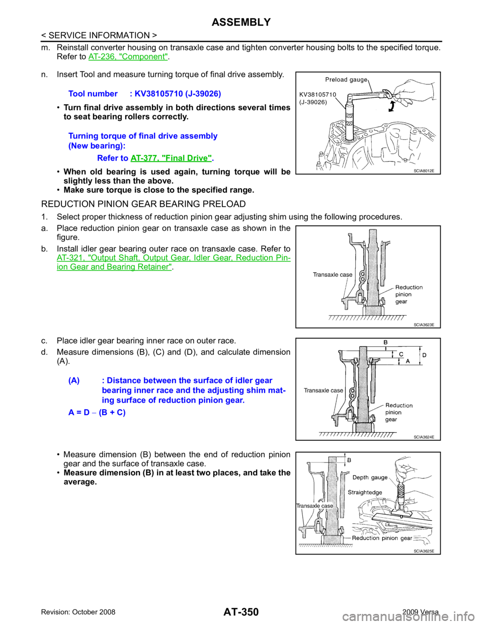
n. Insert Tool and measure turning torque of final drive assembly.
•Turn final drive assembly in both directions several times
to seat bearing rollers correctly.
• When old bearing is used again, turning torque will be
slightly less than the above.
• Make sure torque is close to the specified range.
REDUCTION PINION GEAR BEARING PRELOAD
1. Select proper thickness of reduction pinion gear adjusting shim using the following procedures.
a. Place reduction pinion gear on transaxle case as shown in the figure.
b. Install idler gear bearing outer race on transaxle case. Refer to AT-321, " Output Shaft, Output Gear, Idler Gear, Reduction Pin-
ion Gear and Bearing Retainer " .
c. Place idler gear bearing inner race on outer race.
d. Measure dimensions (B), (C) and (D), and calculate dimension (A).
• Measure dimension (B) between the end of reduction pinion gear and the surface of transaxle case.
• Measure dimension (B) in at least two places, and take the
average. Tool number : KV38105710 (J-39026)
Turning torque of final drive assembly
(New bearing):
Refer to AT-377, " Final Drive " .
SCIA8012E
SCIA3623E
(A) : Distance between the surface of idler gear
bearing inner race and the adjusting shim mat-
ing surface of redu ction pinion gear.
A = D − (B + C) SCIA3624E
SCIA3625E
Page 445 of 4331

BCS
N
O P
BCM (BODY CONTROL MODULE)
System Description INFOID:0000000004306833
BCM (body control module) controls the operation of various electrical units installed on the vehicle.
BCM FUNCTION BCM has a combination switch reading function for reading the operation of combination switches (light, wiper,
washer, turn signal) in addition to the function for c ontrolling the operation of various electrical components.
Also, it functions as an interface that receives signal s from the front air control, and sends signals to ECM
using CAN communication.
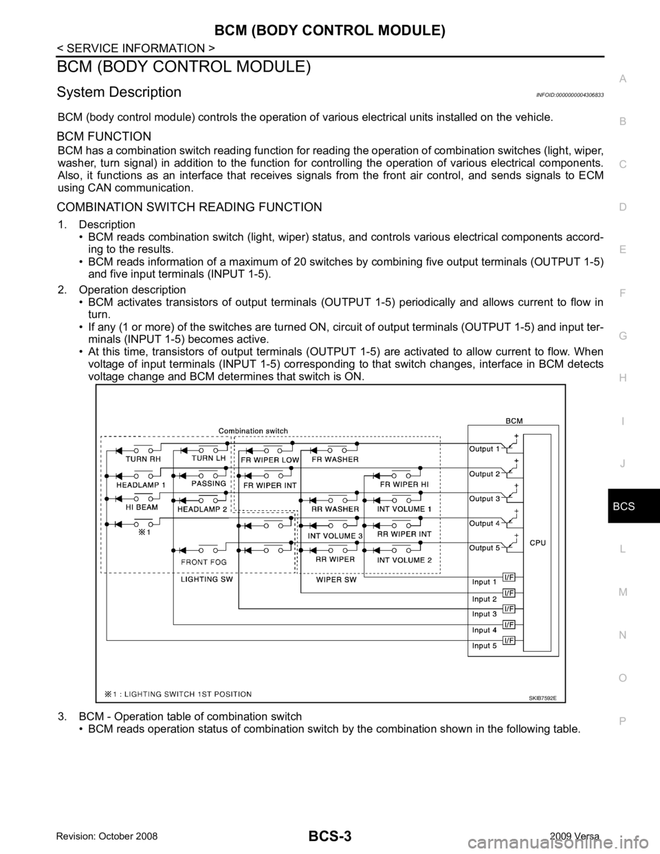
COMBINATION SWITCH READING FUNCTION 1. Description • BCM reads combination switch (light, wiper) status , and controls various electrical components accord-
ing to the results.
• BCM reads information of a maximum of 20 switches by combining five output terminals (OUTPUT 1-5)
and five input terminals (INPUT 1-5).
2. Operation description • BCM activates transistors of output terminals (OUTPUT 1-5) periodically and allows current to flow in
turn.
• If any (1 or more) of the switches are turned ON, circuit of output terminals (OUTPUT 1-5) and input ter-
minals (INPUT 1-5) becomes active.
• At this time, transistors of output terminals (OUTPUT 1-5) are activated to allow current to flow. When
voltage of input terminals (INPUT 1-5) corresponding to that switch changes, interface in BCM detects
voltage change and BCM determines that switch is ON.
3. BCM - Operation table of combination switch • BCM reads operation status of combination switch by the combination shown in the following table.
Page 447 of 4331

BCS
N
O P
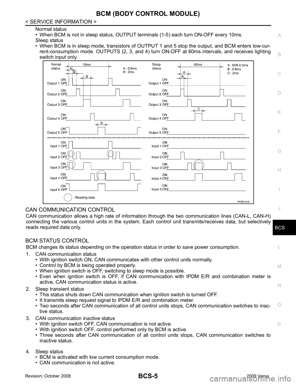
Normal status
• When BCM is not in sleep status, OUTPUT te rminals (1-5) each turn ON-OFF every 10ms.
Sleep status
• When BCM is in sleep mode, transistors of OUTP UT 1 and 5 stop the output, and BCM enters low-cur-
rent-consumption mode. OUTPUTS (2, 3, and 4) turn ON-OFF at 60ms intervals, and receives lighting
switch input only.
CAN COMMUNICATION CONTROL CAN communication allows a high rate of information through the two communication lines (CAN-L, CAN-H)
connecting the various control units in the system. Each control unit transmits/receives data, but selectively
reads required data only.
BCM STATUS CONTROL BCM changes its status depending on the operation stat us in order to save power consumption.
1. CAN communication status • With ignition switch ON, CAN communicates with other control units normally.
• Control by BCM is being operated properly.
• When ignition switch is OFF, switching to sleep mode is possible.
• Even when ignition switch is OFF, if CAN co mmunication with IPDM E/R and combination meter is
active, CAN communication status is active.
2. Sleep transient status • This status shuts down CAN communication when ignition switch is turned OFF.
• It transmits sleep request signal to IPDM E/R and combination meter.
• Two seconds after CAN communication of all control units stops, CAN communication switches to inac-
tive status.
3. CAN communication inactive status • With ignition switch OFF, CAN communication is not active.
• With ignition switch OFF, control performed only by BCM is active.
• Three seconds after CAN communication of all cont rol units stops, CAN communication switches to
inactive status.
4. Sleep status • BCM is activated with low current consumption mode.
• CAN communication is not active.
Page 449 of 4331

BCS
N
O P
CAN Communication System Description INFOID:0000000004306834
Refer to LAN-8, " System Description " .
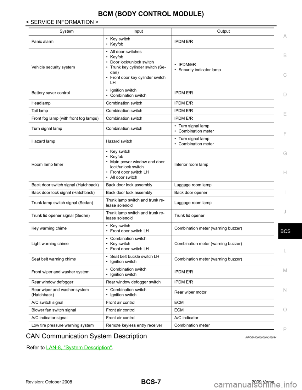
Panic alarm
• Key switch
• Keyfob IPDM E/R
Vehicle security system • All door switches
• Keyfob
• Door lock/unlock switch
• Trunk key cylinder switch (Se-
dan)
• Front door key cylinder switch LH • IPDM/ER
• Security indicator lamp
Battery saver control • Ignition switch
• Combination switch IPDM E/R
Headlamp Combination switch IPDM E/R
Tail lamp Combination switch IPDM E/R
Front fog lamp (with front fog lamps) Combination switch IPDM E/R
Turn signal lamp Combination switch • Turn signal lamp
• Combination meter
Hazard lamp Hazard switch • Turn signal lamp
• Combination meter
Room lamp timer • Key switch
• Keyfob
• Main power window and door lock/unlock switch
• Front door switch LH
• All door switch Interior room lamp
Back door switch signal (Hatchback) Back door lock assembly Luggage room lamp
Back door lock signal (Hatchback) Back door lock assembly Back door opener
Trunk lamp switch signal (Sedan) Trunk lamp switch and trunk re-
lease solenoid Luggage room lamp
Trunk lid opener signal (Sedan) Trunk lamp switch and trunk re-
lease solenoid Trunk lid opener
Key warning chime • Key switch
• Front door switch LH Combination meter (warning buzzer)
Light warning chime • Combination switch
• Key switch
• Front door switch LH Combination meter (warning buzzer)
Seat belt warning chime • Seat belt buckle switch LH
• Ignition switch Combination meter (warning buzzer)
Front wiper and washer system • Combination switch
• Ignition switch IPDM E/R
Rear window defogger Rear window defogger switch IPDM E/R
Rear wiper and washer system
(Hatchback) • Combination switch
• Ignition switch Rear wiper motor
A/C switch signal Front air control ECM
Blower fan switch signal Front air control ECM
A/C indicator signal Front air control A/C indicator
Low tire pressure warning system Remote keyless entry receiver Combination meter System Input Output