Page 528 of 4331
REMOTE KEYLESS ENTRY SYSTEM
BL-67
< SERVICE INFORMATION >
C
D E
F
G H
J
K L
M A
B BL
N
O P
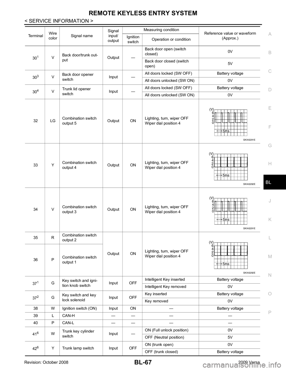
30
1
VBack door/trunk out-
put Output —Back door open (switch
closed) 0V
Back door closed (switch
open) 5V
30 3
VBack door opener
switch Input —All doors locked (SW OFF) Battery voltage
All doors unlocked (SW ON) 0V
30 4
VTrunk lid opener
switch Input —All doors locked (SW OFF) Battery voltage
All doors unlocked (SW ON) 0V
32 LG Combination switch
output 5 Output ONLighting, turn, wiper OFF
Wiper dial position 4
33 Y Combination switch
output 4 Output ON
Lighting, turn, wiper OFF
Wiper dial position 4
34 V Combination switch
output 3 Output ONLighting, turn, wiper OFF
Wiper dial position 4
35 R Combination switch
output 2
Output ONLighting, turn, wiper OFF
Wiper dial position 4
36 P Combination switch
output 1
37 1
GKey switch and igni-
tion knob switch Input OFFIntelligent Key inserted Battery voltage
Intelligent Key removed 0V
37 2
GKey switch and key
lock solenoid Input OFFKey inserted Battery voltage
Key removed 0V
38 W Ignition switch (ON) Input ON — Battery voltage
39 L CAN-H — — — —
40 P CAN-L — — — —
41 6
WTrunk key cylinder
switch Input —ON (Full unlock position) 0V
OFF (Neutral position) 5V
42 6
Y Trunk lamp switch Input OFF ON (trunk open) 0V
OFF (trunk closed) Battery voltage
Terminal
Wire
color Signal name Signal
input/
output Measuring condition
Reference value or waveform
(Approx.)
Ignition
switch Operation or condition SKIA5291E
SKIA5292E
SKIA5291E
SKIA5292E
Page 572 of 4331
INTELLIGENT KEY SYSTEM
BL-111
< SERVICE INFORMATION >
C
D E
F
G H
J
K L
M A
B BL
N
O P
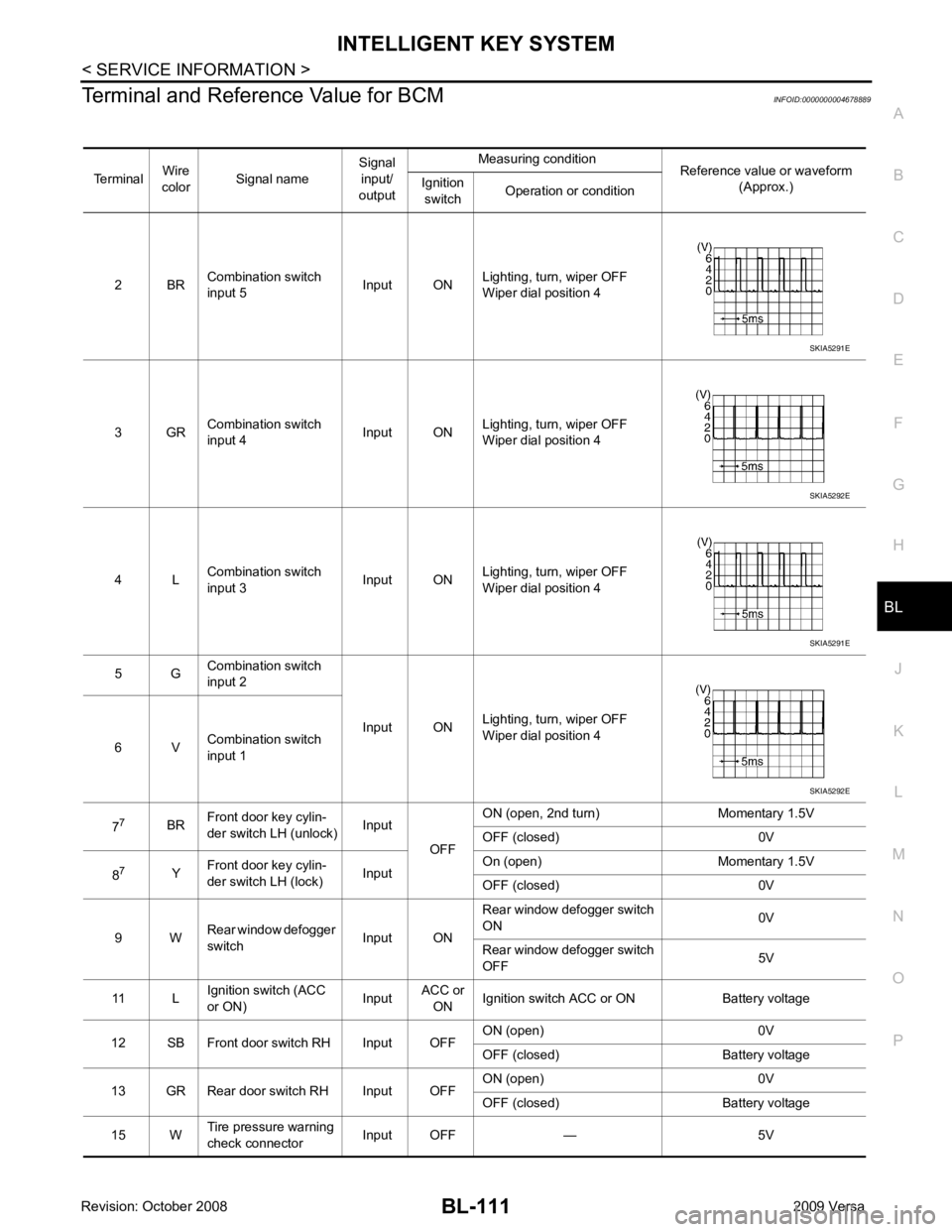
Terminal and Reference Value for BCM
INFOID:0000000004678889
Terminal Wire
color Signal name Signal
input/
output Measuring condition
Reference value or waveform
(Approx.)
Ignition
switch Operation or condition
2 BR Combination switch
input 5 Input ONLighting, turn, wiper OFF
Wiper dial position 4
3 GR Combination switch
input 4 Input ONLighting, turn, wiper OFF
Wiper dial position 4
4 L Combination switch
input 3 Input ONLighting, turn, wiper OFF
Wiper dial position 4
5 G Combination switch
input 2
Input ONLighting, turn, wiper OFF
Wiper dial position 4
6 V Combination switch
input 1
7 7
BRFront door key cylin-
der switch LH (unlock) Input
OFFON (open, 2nd turn) Momentary 1.5V
OFF (closed) 0V
8 7
YFront door key cylin-
der switch LH (lock) InputOn (open) Momentary 1.5V
OFF (closed) 0V
9 W Rear window defogger
switch Input ONRear window defogger switch
ON 0V
Rear window defogger switch
OFF 5V
11 L Ignition switch (ACC
or ON) InputACC or
ON Ignition switch ACC or ON Battery voltage
12 SB Front door switch RH Input OFF ON (open) 0V
OFF (closed) Battery voltage
13 GR Rear door switch RH Input OFF ON (open) 0V
OFF (closed) Battery voltage
15 W Tire pressure warning
check connector Input OFF — 5V SKIA5291E
SKIA5292E
SKIA5291E
SKIA5292E
Page 574 of 4331
INTELLIGENT KEY SYSTEM
BL-113
< SERVICE INFORMATION >
C
D E
F
G H
J
K L
M A
B BL
N
O P
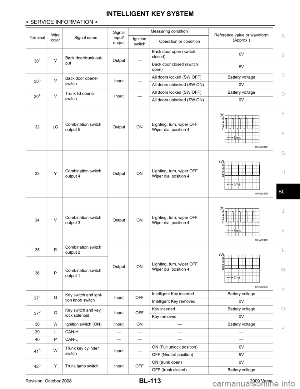
30
1
VBack door/trunk out-
put Output —Back door open (switch
closed) 0V
Back door closed (switch
open) 5V
30 3
VBack door opener
switch Input —All doors locked (SW OFF) Battery voltage
All doors unlocked (SW ON) 0V
30 4
VTrunk lid opener
switch Input —All doors locked (SW OFF) Battery voltage
All doors unlocked (SW ON) 0V
32 LG Combination switch
output 5 Output ONLighting, turn, wiper OFF
Wiper dial position 4
33 Y Combination switch
output 4 Output ON
Lighting, turn, wiper OFF
Wiper dial position 4
34 V Combination switch
output 3 Output ONLighting, turn, wiper OFF
Wiper dial position 4
35 R Combination switch
output 2
Output ONLighting, turn, wiper OFF
Wiper dial position 4
36 P Combination switch
output 1
37 1
GKey switch and igni-
tion knob switch Input OFFIntelligent Key inserted Battery voltage
Intelligent Key removed 0V
37 2
GKey switch and key
lock solenoid Input OFFKey inserted Battery voltage
Key removed 0V
38 W Ignition switch (ON) Input ON — Battery voltage
39 L CAN-H — — — —
40 P CAN-L — — — —
41 6
WTrunk key cylinder
switch Input —ON (Full unlock position) 0V
OFF (Neutral position) 5V
42 6
Y Trunk lamp switch Input OFF ON (trunk open) 0V
OFF (trunk closed) Battery voltage
Terminal
Wire
color Signal name Signal
input/
output Measuring condition
Reference value or waveform
(Approx.)
Ignition
switch Operation or condition SKIA5291E
SKIA5292E
SKIA5291E
SKIA5292E
Page 618 of 4331
INTELLIGENT KEY SYSTEM
BL-157
< SERVICE INFORMATION >
C
D E
F
G H
J
K L
M A
B BL
N
O P
Horn Function Check
INFOID:0000000004305072
First perform the “SELF-DIAG RESULTS” of “BCM” with CONSULT-III, then perform the trouble diag-
nosis of malfunction system indicated in “ SELF-DIAG RESULTS” of “BCM”. Refer to BCS-17, " CAN
Communication Inspection Using CONSULT-III (Self-Diagnosis) " .
1.
CHECK HORN OPERATION
Check if horn sounds with horn switch.
Does horn operate? Yes >> GO TO 2
No >> Check horn circuit. Refer to WW-38 .
2.
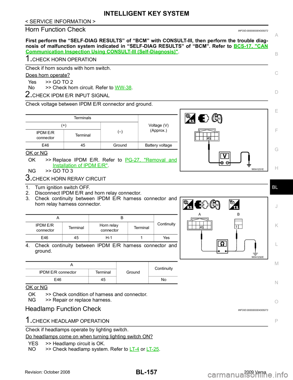
CHECK IPDM E/R INPUT SIGNAL
Check voltage between IPDM E/R connector and ground.
OK or NG OK >> Replace IPDM E/R. Refer to
PG-27, " Removal and
Installation of IPDM E/R " .
NG >> GO TO 3 3.
CHECK HORN RERAY CIRCUIT
1. Turn ignition switch OFF.
2. Disconnect IPDM E/R and horn relay connector.
3. Check continuity between IPDM E/R harness connector and horn relay harness connector.
4. Check continuity between IPDM E/R harness connector and ground.
OK or NG OK >> Check condition of harness and connector.
NG >> Repair or replace harness.
Headlamp Function Check INFOID:00000000043050731.
CHECK HEADLAMP OPERATION
Check if headlamps operate by lighting switch.
Do headlamps come on when turning lighting switch ON? YES >> Headlamp circuit is OK.
NO >> Check headlamp system. Refer to LT-4 or
LT-25 .
Terminals
Voltage (V)(Approx.)
(+)
(–)
IPDM E/R
connector Terminal
E46 45 Ground Ba ttery voltage WIIA1251E
A B
Continuity
IPDM E/R
connector Terminal
Horn relay
connector Terminal
E46 45 H-1 1 Yes
A GroundContinuity
IPDM E/R connector Terminal
E46 45 No WIIA1252E
Page 636 of 4331
BACK DOOR LOCK
BL-175
< SERVICE INFORMATION >
C
D E
F
G H
J
K L
M A
B BL
N
O P
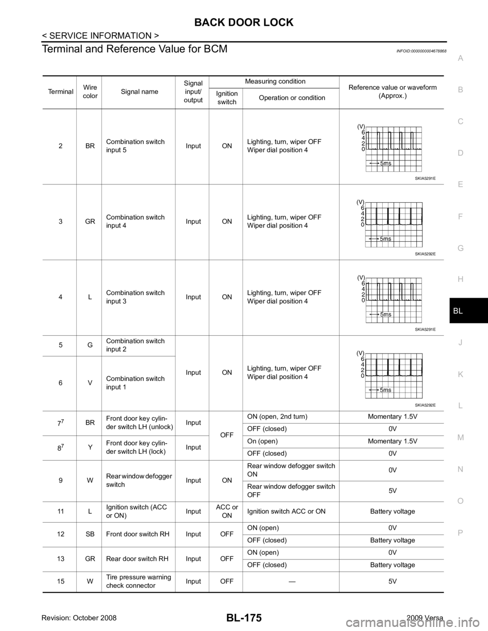
Terminal and Reference Value for BCM
INFOID:0000000004678868
Terminal Wire
color Signal name Signal
input/
output Measuring condition
Reference value or waveform
(Approx.)
Ignition
switch Operation or condition
2 BR Combination switch
input 5 Input ONLighting, turn, wiper OFF
Wiper dial position 4
3 GR Combination switch
input 4 Input ONLighting, turn, wiper OFF
Wiper dial position 4
4 L Combination switch
input 3 Input ONLighting, turn, wiper OFF
Wiper dial position 4
5 G Combination switch
input 2
Input ONLighting, turn, wiper OFF
Wiper dial position 4
6 V Combination switch
input 1
7 7
BRFront door key cylin-
der switch LH (unlock) Input
OFFON (open, 2nd turn) Momentary 1.5V
OFF (closed) 0V
8 7
YFront door key cylin-
der switch LH (lock) InputOn (open) Momentary 1.5V
OFF (closed) 0V
9 W Rear window defogger
switch Input ONRear window defogger switch
ON 0V
Rear window defogger switch
OFF 5V
11 L Ignition switch (ACC
or ON) InputACC or
ON Ignition switch ACC or ON Battery voltage
12 SB Front door switch RH Input OFF ON (open) 0V
OFF (closed) Battery voltage
13 GR Rear door switch RH Input OFF ON (open) 0V
OFF (closed) Battery voltage
15 W Tire pressure warning
check connector Input OFF — 5V SKIA5291E
SKIA5292E
SKIA5291E
SKIA5292E
Page 638 of 4331
BACK DOOR LOCK
BL-177
< SERVICE INFORMATION >
C
D E
F
G H
J
K L
M A
B BL
N
O P
30
1
VBack door/trunk out-
put Output —Back door open (switch
closed) 0V
Back door closed (switch
open) 5V
30 3
VBack door opener
switch Input —All doors locked (SW OFF) Battery voltage
All doors unlocked (SW ON) 0V
30 4
VTrunk lid opener
switch Input —All doors locked (SW OFF) Battery voltage
All doors unlocked (SW ON) 0V
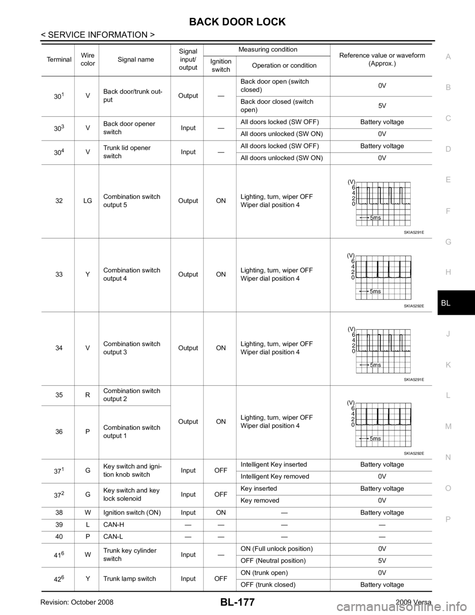
32 LG Combination switch
output 5 Output ONLighting, turn, wiper OFF
Wiper dial position 4
33 Y Combination switch
output 4 Output ON
Lighting, turn, wiper OFF
Wiper dial position 4
34 V Combination switch
output 3 Output ONLighting, turn, wiper OFF
Wiper dial position 4
35 R Combination switch
output 2
Output ONLighting, turn, wiper OFF
Wiper dial position 4
36 P Combination switch
output 1
37 1
GKey switch and igni-
tion knob switch Input OFFIntelligent Key inserted Battery voltage
Intelligent Key removed 0V
37 2
GKey switch and key
lock solenoid Input OFFKey inserted Battery voltage
Key removed 0V
38 W Ignition switch (ON) Input ON — Battery voltage
39 L CAN-H — — — —
40 P CAN-L — — — —
41 6
WTrunk key cylinder
switch Input —ON (Full unlock position) 0V
OFF (Neutral position) 5V
42 6
Y Trunk lamp switch Input OFF ON (trunk open) 0V
OFF (trunk closed) Battery voltage
Terminal
Wire
color Signal name Signal
input/
output Measuring condition
Reference value or waveform
(Approx.)
Ignition
switch Operation or condition SKIA5291E
SKIA5292E
SKIA5291E
SKIA5292E
Page 654 of 4331
BL
N
O P
TRUNK LID
Fitting Adjustment INFOID:0000000004305097
Longitudinal and latera l clearance adjustment
1. With the striker released, loosen the trunk lid hinge nuts and close the trunk lid.
2. Make the lateral clearance and the clearance to the rear window glass equal. Then open the trunk lid to tighten the nuts.
Surface height adjustment 1. Loosen the striker bolts. Raise the striker to t he top position, and temporarily tighten the upper bolt.
2. Close the trunk lid lightly and adjust the surface height. Then open the trunk lid and tighten the striker bolts.
Trunk Lid Assembly INFOID:0000000004305098
REMOVAL 1. Remove the trunk lid finisher. Refer to EI-55 .
2. Remove the trunk lid wire harness. 1. Rear fender 2. Trunk lid 3. Rear combination lamp
4. Rear bumper fascia a. 4.0 ± 1.0 mm (0.16 ± 0.04 in) b. 3.5 ± 1.0 mm (0.14 ± 0.04 in)
c. 4.5 ± 1.7 mm (0.03 ± 0.06 in) d. 7.0 ± 2.2 mm (0.28 ± 0.09 in)
Page 660 of 4331
TRUNK LID OPENER
BL-199
< SERVICE INFORMATION >
C
D E
F
G H
J
K L
M A
B BL
N
O P
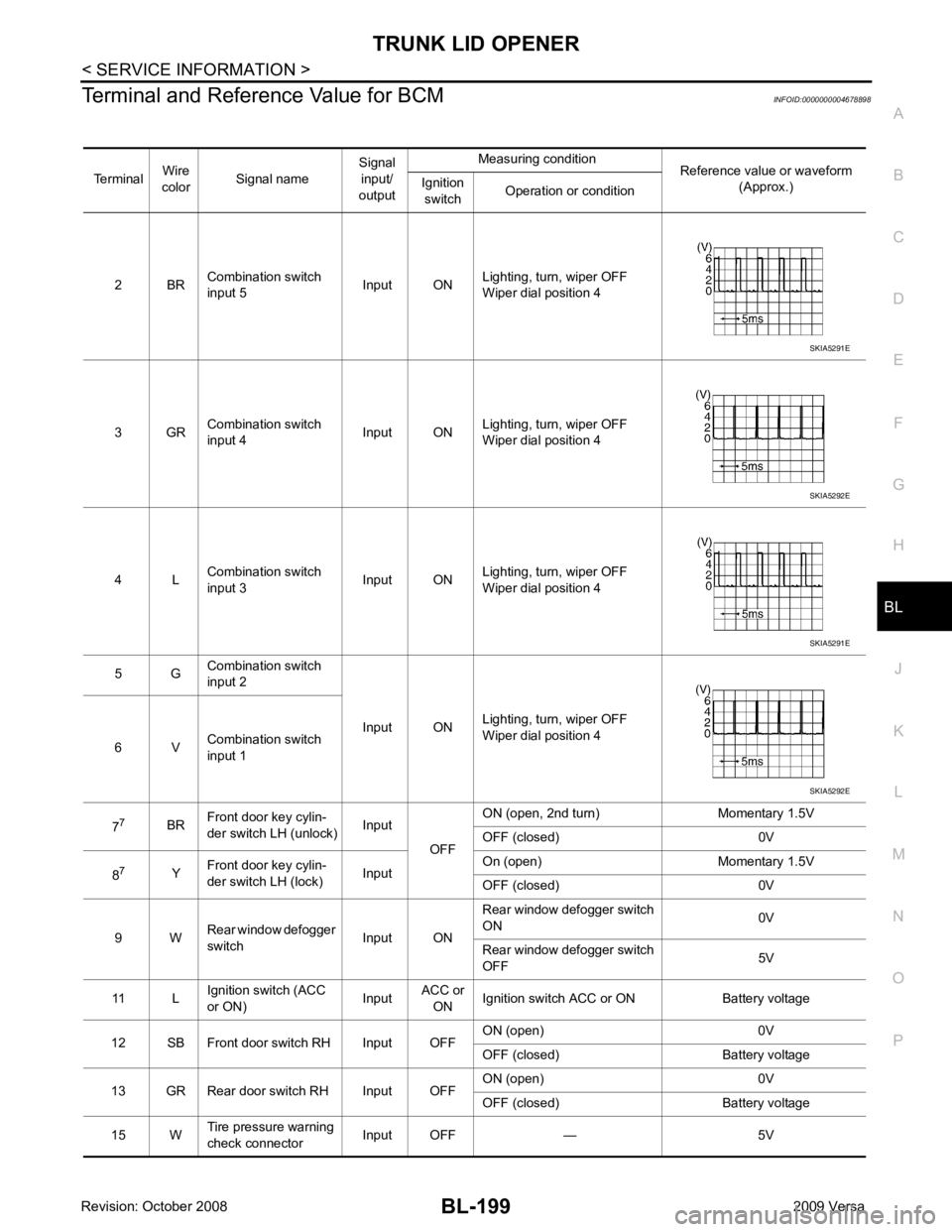
Terminal and Reference Value for BCM
INFOID:0000000004678898
Terminal Wire
color Signal name Signal
input/
output Measuring condition
Reference value or waveform
(Approx.)
Ignition
switch Operation or condition
2 BR Combination switch
input 5 Input ONLighting, turn, wiper OFF
Wiper dial position 4
3 GR Combination switch
input 4 Input ONLighting, turn, wiper OFF
Wiper dial position 4
4 L Combination switch
input 3 Input ONLighting, turn, wiper OFF
Wiper dial position 4
5 G Combination switch
input 2
Input ONLighting, turn, wiper OFF
Wiper dial position 4
6 V Combination switch
input 1
7 7
BRFront door key cylin-
der switch LH (unlock) Input
OFFON (open, 2nd turn) Momentary 1.5V
OFF (closed) 0V
8 7
YFront door key cylin-
der switch LH (lock) InputOn (open) Momentary 1.5V
OFF (closed) 0V
9 W Rear window defogger
switch Input ONRear window defogger switch
ON 0V
Rear window defogger switch
OFF 5V
11 L Ignition switch (ACC
or ON) InputACC or
ON Ignition switch ACC or ON Battery voltage
12 SB Front door switch RH Input OFF ON (open) 0V
OFF (closed) Battery voltage
13 GR Rear door switch RH Input OFF ON (open) 0V
OFF (closed) Battery voltage
15 W Tire pressure warning
check connector Input OFF — 5V SKIA5291E
SKIA5292E
SKIA5291E
SKIA5292E