Page 1591 of 4331

EC
NP
O
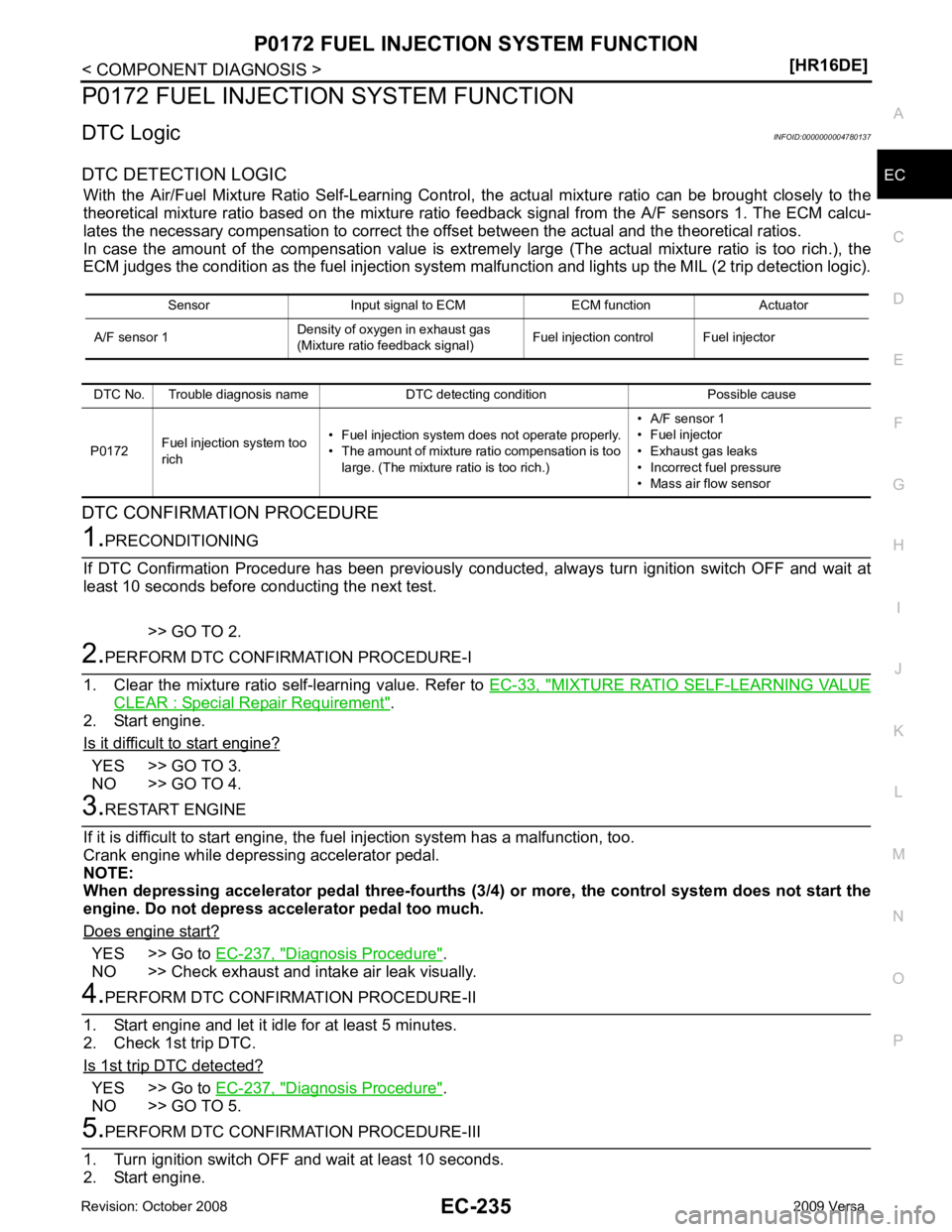
P0172 FUEL INJECTION SYSTEM FUNCTION
DTC Logic INFOID:0000000004780137
DTC DETECTION LOGIC With the Air/Fuel Mixture Ratio Self-Learning Control, the actual mixture ratio can be brought closely to the
theoretical mixture ratio based on the mixture ratio f eedback signal from the A/F sensors 1. The ECM calcu-
lates the necessary compensation to correct the of fset between the actual and the theoretical ratios.
In case the amount of the compensation value is extrem ely large (The actual mixture ratio is too rich.), the
ECM judges the condition as the fuel injection system malfunction and lights up the MIL (2 trip detection logic).
DTC CONFIRMATION PROCEDURE MIXTURE RATIO SELF-LEARNING VALUE
CLEAR : Special Repair Requirement " .
2. Start engine.
Is it difficult to start engine? YES >> GO TO 3.
NO >> GO TO 4. YES >> Go to
EC-237, " Diagnosis Procedure " .
NO >> Check exhaust and intake air leak visually. YES >> Go to
EC-237, " Diagnosis Procedure " .
NO >> GO TO 5. DTC No. Trouble diagnosis name DTC detecting condition Possible cause
P0172 Fuel injection system too
rich • Fuel injection system does not operate properly.
• The amount of mixture ratio compensation is too large. (The mixture ratio is too rich.) • A/F sensor 1
• Fuel injector
• Exhaust gas leaks
• Incorrect fuel pressure
• Mass air flow sensor
Page 1609 of 4331

EC
NP
O
P0300, P0301, P0302, P0303, P0304 MISFIRE
DTC Logic INFOID:0000000004780152
DTC DETECTION LOGIC When a misfire occurs, engine speed will fluctuate. If the engine speed fluctuates enough to cause the crank-
shaft position (CKP) sensor (POS) signal to vary , ECM can determine that a misfire is occurring.
The misfire detection logic consists of the following two conditions.
1. One Trip Detection Logic (Three Way Catalyst Damage) On the 1st trip , when a misfire condition occurs that can damage the three way catalyst (TWC) due to
overheating, the MIL will blink.
When a misfire condition occurs, the ECM monitors the CKP sensor signal every 200 engine revolutions
for a change.
When the misfire condition decreases to a level t hat will not damage the TWC, the MIL will turn off.
If another misfire condition occurs that can damage the TWC on a second trip, the MIL will blink.
When the misfire condition decreases to a level t hat will not damage the TWC, the MIL will remain on.
If another misfire condition occurs that can damage the TWC, the MIL will begin to blink again.
2. Two Trip Detection Logic (Exhaust quality deterioration) For misfire conditions that will not damage the TWC (but will affect vehicle emissions), the MIL will only
light when the misfire is detected on a second trip. Du ring this condition, the ECM monitors the CKP sen-
sor signal every 1,000 engine revolutions.
A misfire malfunction can be detected on any one cylinder or on multiple cylinders.
DTC CONFIRMATION PROCEDURE YES >> Go to
EC-254, " Diagnosis Procedure " .
NO >> GO TO 3. DTC No. Trouble diagnosis name DTC detecting condition Possible cause
P0300 Multiple cylinder misfire detected Multiple cylinders misfire. • Improper spark plug • Insufficient compression
• Incorrect fuel pressure
• The fuel injector circuit is open or shorted
• Fuel injector
• Intake air leak
• The ignition signal circuit is open or shorted
• Lack of fuel
• Signal plate
• A/F sensor 1
• Incorrect PCV hose connection
P0301 No.1 cylinder misfire detected No. 1 cylinder misfires.
P0302 No. 2 cylinder misfire detected No. 2 cylinder misfires.
P0303 No. 3 cylinder misfire detected No. 3 cylinder misfires.
P0304 No. 4 cylinder misfire detected No. 4 cylinder misfires.
Page 1637 of 4331
EC
NP
O
3. Disconnect vacuum hose connected to EVAP canister
purge volume control solenoid valve at EVAP ser-
vice port and install vacuum gauge. For the location of EVAP service port, refer to EC-74, " System
Description " .
4. Start engine and let it idle.
Do not depress accelerator pedal even slightly.
5. Check vacuum gauge indication before 60 seconds passed after starting engine.
6. Revving engine up to 2,000rpm after 100 seconds passed after starting engine.
Is the inspection result normal? YES >> GO TO 7.
NO >> GO TO 4. System Description " .
Is the inspection result normal? YES >> GO TO 5.
NO >> Repair it. YES-1 >> With CONSULT-III: GO TO 6.
YES-2 >> Without CONSULT-III: GO TO 7.
NO >> Repair or clean hoses and/or purge port. YES >> GO TO 8.
NO >> GO TO 7. Vacuum should not exist.
Vacuum should exist. SEF368U
Page 1738 of 4331
YES >> GO TO 4.
NO >> GO TO 2. YES >> GO TO 4.
NO >> GO TO 3. YES >> GO TO 5.
NO >> Repair open circuit or short to ground or short to power in harness or connectors. Component Inspection (Stop Lamp Switch) " .
Is the inspection result normal? YES >> GO TO 6.Brake pedal Stop lamp
Fully released Not illuminated
Slightly depressed Illuminated Stop lamp switch
Ground Voltage
Connector Terminal
E13 1 Ground Battery voltage
Page 1739 of 4331
EC
NP
O
NO >> Replace stop lamp switch. Diagnosis Procedure " .
>> INSPECTION END
Component Inspection (Stop Lamp Switch) INFOID:0000000004780300YES >> INSPECTION END
NO >> GO TO 2. Inspection and Adjustment " .
2. Check the continuity between stop lamp switch terminals under the following conditions.
Is the inspection result normal? YES >> INSPECTION END
NO >> Replace stop lamp switch. Terminals Condition Continuity
1 and 2 Brake pedal Fully released Not existed
Slightly depressed Existed
Page 1784 of 4331
YES >> GO TO 2.
NO >> Go to EC-428, " Diagnosis Procedure " .
YES >> GO TO 3.
NO >> Go to EC-428, " Diagnosis Procedure " .
YES >> INSPECTION END
NO >> Go to EC-428, " Diagnosis Procedure " .
Diagnosis Procedure INFOID:0000000004780356 Compo-
nent Function Check " .
Which circuit is related to the incident? Rear window defogger>>GO TO 2.
Headlamp>>GO TO 3.
Heater fan>>GO TO 4. Work Flow " .
Monitor item Condition Indication
LOAD SIGNAL Rear window defogger switch ON ON
OFF OFF Monitor item Condition Indication
LOAD SIGNAL Lighting switch ON at 2nd position ON
OFF OFF Monitor item Condition Indication
HEATER FAN SW Heater fan control switch ON ON
OFF OFF
Page 1802 of 4331
EC-446< COMPONENT DIAGNOSIS >
[HR16DE]
MALFUNCTION INDICATOR LAMP
MALFUNCTION INDICATOR LAMP
Description INFOID:0000000004780371
The Malfunction Indicator Lamp (MIL) is located on the combination
meter.
The MIL will light up when the ignition switch is turned ON without
the engine running. This is a bulb check.
When the engine is started, the MIL should go off. If the MIL remains
on, the on board diagnostic system has detected an engine system
malfunction.
For details, refer to EC-90, " Diagnosis Description " .
Component Function Check INFOID:00000000047803721.
CHECK MIL FUNCTION
1. Turn ignition switch ON.
2. Make sure that MIL lights up.
Is the inspection result normal? YES >> INSPECTION END
NO >> Go to EC-448, " Diagnosis Procedure " . SEF217U
Page 1817 of 4331

EC
NP
O
ECU DIAGNOSIS
ECM
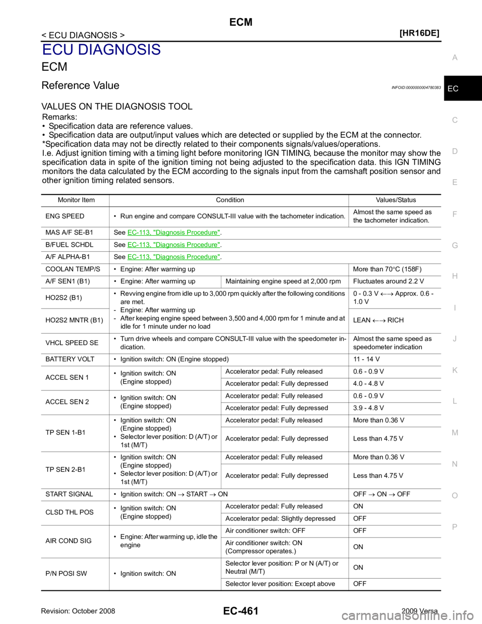
Reference Value INFOID:0000000004780383
VALUES ON THE DIAGNOSIS TOOL Remarks:
• Specification data are reference values.
• Specification data are output/input values which are detected or supplied by the ECM at the connector.
*Specification data may not be directly relat ed to their components signals/values/operations.
I.e. Adjust ignition timing with a timing light before m onitoring IGN TIMING, because the monitor may show the
specification data in spite of the ignition timing not bei ng adjusted to the specification data. this IGN TIMING
monitors the data calculated by the ECM according to the signals input from the camshaft position sensor and
other ignition timing related sensors.
Monitor Item Condition Values/Status
ENG SPEED • Run engine and compare CONSULT-III value with the tachometer indication. Almost the same speed as
the tachometer indication.
MAS A/F SE-B1 See EC-113, " Diagnosis Procedure " .
B/FUEL SCHDL See EC-113, " Diagnosis Procedure " .
A/F ALPHA-B1 See EC-113, " Diagnosis Procedure " .
COOLAN TEMP/S • Engine: After warming up More than 70 °C (158F)
A/F SEN1 (B1) • Engine: After warming up Maintaining engine speed at 2,000 rpm Fluctuates around 2.2 V
HO2S2 (B1) • Revving engine from idle up to 3,000 rpm quickly after the following conditions
are met.
- Engine: After warming up
- After keeping engine speed between 3,500 and 4,000 rpm for 1 minute and at
idle for 1 minute under no load 0 - 0.3 V
←→ Approx. 0.6 -
1.0 V
HO2S2 MNTR (B1) LEAN ←→ RICH
VHCL SPEED SE • Turn drive wheels and compare CONSULT-III value with the speedometer in-
dication. Almost the same speed as
speedometer indication
BATTERY VOLT • Ignition switch: ON (Engine stopped) 11 - 14 V
ACCEL SEN 1 • Ignition switch: ON
(Engine stopped) Accelerator pedal: Fully released 0.6 - 0.9 V
Accelerator pedal: Fully depressed 4.0 - 4.8 V
ACCEL SEN 2 • Ignition switch: ON
(Engine stopped) Accelerator pedal: Fully released 0.6 - 0.9 V
Accelerator pedal: Fully depressed 3.9 - 4.8 V
TP SEN 1-B1 • Ignition switch: ON
(Engine stopped)
• Selector lever position: D (A/T) or 1st (M/T) Accelerator pedal: Fully released More than 0.36 V
Accelerator pedal: Fully depressed Less than 4.75 V
TP SEN 2-B1 • Ignition switch: ON
(Engine stopped)
• Selector lever position: D (A/T) or 1st (M/T) Accelerator pedal: Fully released More than 0.36 V
Accelerator pedal: Fully depressed Less than 4.75 V
START SIGNAL • Ignition switch: ON → START → ON OFF → ON → OFF
CLSD THL POS • Ignition switch: ON
(Engine stopped) Accelerator pedal: Fully released ON
Accelerator pedal: Slightly depressed OFF
AIR COND SIG • Engine: After warming up, idle the
engine Air conditioner switch: OFF OFF
Air conditioner switch: ON
(Compressor operates.) ON
P/N POSI SW • Ignition switch: ON Selector lever position: P or N (A/T) or
Neutral (M/T) ON
Selector lever position: Except above OFF