2009 NISSAN LATIO light
[x] Cancel search: lightPage 1914 of 4331

Emission-
related Diagnostic Information " .
HOW TO SWITCH DIAGNOSTIC TEST MODE
NOTE:
• It is better to count the ti me accurately with a clock.
• It is impossible to switch the di agnostic mode when an accelerator pedal position sensor circuit has
a malfunction.
• Always ECM returns to Diagnostic Test Mode I after ignition switch is turned OFF.
How to Set Diagnostic Test Mode II (Self-diagnostic Results)
1. Confirm that accelerator pedal is fully releas ed, turn ignition switch ON and wait 3 seconds.
2. Repeat the following procedure quickly five times within 5 seconds.
a. Fully depress the accelerator pedal.
b. Fully release the accelerator pedal.
3. Wait 7 seconds, fully depress the accelerator pedal and keep it for approx. 10 seconds until the MIL starts blinking.
4. Fully release the accelerator pedal. Diagnostic Test
Mode KEY and ENG.
Status Function Explanation of Function
Mode I Ignition switch in ON position
Engine stopped BULB CHECK This function checks the MIL bulb for damage (blown, open
circuit, etc.).
If the MIL does not come on, check MIL circuit.
Engine running MALFUNCTION WARNING This is a usual driving condition. When a malfunction is de-
tected twice in two consecutive driving cycles (two trip de-
tection logic), the MIL will light up to inform the driver that a
malfunction has been detected.
The following malfunctions will light up or blink the MIL in
the 1st trip.
• Misfire (Possible three way catalyst damage)
• One trip detection diagnoses
Mode II Ignition switch in ON position
Engine stopped SELF-DIAGNOSTIC
RESULTS This function allows DTCs an
d 1st trip DTCs to be read.
Page 1918 of 4331
![NISSAN LATIO 2009 Service Repair Manual EC-562< SERVICE INFOMATION >
[MR TYPE 1]
ON BOARD DIAGNOSTIC (OBD) SYSTEM
EXPLANATION FOR DRIVING PATTERNS FOR “M ISFIRE <EXHAUST QUALITY DETERIORA-
TION>”, “FUEL INJECTION SYSTEM”
<Dr NISSAN LATIO 2009 Service Repair Manual EC-562< SERVICE INFOMATION >
[MR TYPE 1]
ON BOARD DIAGNOSTIC (OBD) SYSTEM
EXPLANATION FOR DRIVING PATTERNS FOR “M ISFIRE <EXHAUST QUALITY DETERIORA-
TION>”, “FUEL INJECTION SYSTEM”
<Dr](/manual-img/5/57359/w960_57359-1917.png)
EC-562< SERVICE INFOMATION >
[MR TYPE 1]
ON BOARD DIAGNOSTIC (OBD) SYSTEM
EXPLANATION FOR DRIVING PATTERNS FOR “M ISFIRE
Driving pattern B means the vehicle operation as follows: *1: When the same malfunction is de-
tected in two consecutive trips, MIL
will light up. *2: MIL will go off after vehicle is driven 3
times (pattern B) without any mal-
functions. *3: When the same malfunction is de-
tected in two consecutive trips, the
DTC and the freeze frame data will be
stored in ECM.
*4: The DTC and the freeze frame data will not be displayed any longer after
vehicle is driven 80 times (pattern C)
without the same malfunction. (The
DTC and the freeze frame data still
remain in ECM.) *5: When a malfunction is detected for
the first time, the 1st trip DTC and the
1st trip freeze frame data will be
stored in ECM. *6: The 1st trip DTC and the 1st trip
freeze frame data will be cleared at
the moment OK is detected.
*7: When the same malfunction is de- tected in the 2nd trip, the 1st trip
freeze frame data will be cleared. *8: 1st trip DTC will
be cleared when ve-
hicle is driven once (pattern C) with-
out the same malfunction after DTC
is stored in ECM. SEF392S
Page 1920 of 4331
![NISSAN LATIO 2009 Service Repair Manual EC-564< SERVICE INFOMATION >
[MR TYPE 1]
ON BOARD DIAGNOSTIC (OBD) SYSTEM
EXPLANATION FOR DRIVING PATTERNS EXCEPT FOR “MISFIRE <EXHAUST QUALITY DETE-
RIORATION>”, “FUEL INJECTION SYSTEM” *1: NISSAN LATIO 2009 Service Repair Manual EC-564< SERVICE INFOMATION >
[MR TYPE 1]
ON BOARD DIAGNOSTIC (OBD) SYSTEM
EXPLANATION FOR DRIVING PATTERNS EXCEPT FOR “MISFIRE <EXHAUST QUALITY DETE-
RIORATION>”, “FUEL INJECTION SYSTEM” *1:](/manual-img/5/57359/w960_57359-1919.png)
EC-564< SERVICE INFOMATION >
[MR TYPE 1]
ON BOARD DIAGNOSTIC (OBD) SYSTEM
EXPLANATION FOR DRIVING PATTERNS EXCEPT FOR “MISFIRE
tected in two consecutive trips, MIL
will light up. *2: MIL will go off after vehicle is driven 3
times (pattern B) without any mal-
functions. *3: When the same malfunction is de-
tected in two consecutive trips, the
DTC and the freeze frame data will be
stored in ECM.
*4: The DTC and the freeze frame data will not be displayed any longer after
vehicle is driven 40 times (pattern A)
without the same malfunction.
(The DTC and the freeze frame data
still remain in ECM.) *5: When a malfunction is detected for
the first time, the 1st trip DTC and the
1st trip freeze frame data will be
stored in ECM. *6: 1st trip DTC will
be cleared after vehi-
cle is driven once (pattern B) without
the same malfunction.
*7: When the same malfunction is de- tected in the 2nd trip, the 1st trip
freeze frame data will be cleared. SEF393SD
Page 1925 of 4331
![NISSAN LATIO 2009 Service Repair Manual BASIC SERVICE PROCEDURE
EC-569
< SERVICE INFOMATION >
[MR TYPE 1] C
D E
F
G H
I
J
K L
M A EC
NP
O
Yes >> GO TO 14.
No >> 1. Follow the instruction of Idle Air Volume Learning. 2. GO TO 4. 14.
CHECK TA NISSAN LATIO 2009 Service Repair Manual BASIC SERVICE PROCEDURE
EC-569
< SERVICE INFOMATION >
[MR TYPE 1] C
D E
F
G H
I
J
K L
M A EC
NP
O
Yes >> GO TO 14.
No >> 1. Follow the instruction of Idle Air Volume Learning. 2. GO TO 4. 14.
CHECK TA](/manual-img/5/57359/w960_57359-1924.png)
BASIC SERVICE PROCEDURE
EC-569
< SERVICE INFOMATION >
[MR TYPE 1] C
D E
F
G H
I
J
K L
M A EC
NP
O
Yes >> GO TO 14.
No >> 1. Follow the instruction of Idle Air Volume Learning. 2. GO TO 4. 14.
CHECK TARGET IDLE SPEED AGAIN
With CONSULT-III
1. Start engine and warm it up to normal operating temperature.
2. Read idle speed in “DATA MONITOR” mode with CONSULT-III. Refer to EC-570, " Idle Speed and Ignition
Timing Check " .
Without CONSULT-III
1. Start engine and warm it up to normal operating temperature.
2. Check idle speed. Refer to EC-570, " Idle Speed and Ignition Timing Check " .
OK or NG OK >> GO TO 15.
NG >> GO TO 17. 15.
CHECK IGNITION TIMING AGAIN
1. Run engine at idle.
2. Check ignition timing with a timing light. Refer to EC-570, " Idle Speed and Ignition Timing Check " .
- Timing indicator (1)
OK or NG OK >> GO TO 19
NG >> GO TO 16. 16.
CHECK TIMING CHAIN INSTALLATION
Check timing chain installation. Refer to EM-160 .
OK or NG OK >> GO TO 17.
NG >> 1. Repair the timing chain installation.
2. GO TO 4. 17.
DETECT MALFUNCTIONING PART
Check the following.
• Check crankshaft position sensor (POS) and circuit. Refer to EC-775 .
• Check camshaft position s ensor (PHASE) and circuit.
Refer to EC-781 .
OK or NG OK >> GO TO 18.
NG >> 1. Repair or replace. 2. GO TO 4. 18.
CHECK ECM FUNCTION M/T: 700
± 50 rpm (in Neutral position)
A/T: 700 ± 50 rpm (in P or N position)
CVT: 700 ± 50 rpm (in P or N position)
M/T: 700 ± 50 rpm (in Neutral position)
A/T: 700 ± 50 rpm (in P or N position)
CVT: 700 ± 50 rpm (in P or N position) M/T: 13
± 5 ° BTDC (in Neutral position)
A/T: 13 ± 5 ° BTDC (in P or N position)
CVT: 13 ± 5 ° BTDC (in P or N position) PBIB3263E
Page 1926 of 4331

ECM Re-communicating Function " .
>> GO TO 4. Yes >> 1. Perform
EC-572, " VIN Registration " .
2. INSPECTION END
No >> INSPECTION END
Idle Speed and Ignition Timing Check INFOID:0000000004537044
IDLE SPEED With CONSULT-III
Check idle speed in “DATA MONITOR” mode with CONSULT-III.
With GST
Check idle speed in Service $01 with GST.
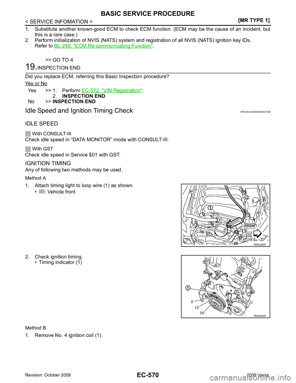
IGNITION TIMING
Any of following two methods may be used.
Method A
1. Attach timing light to loop wire (1) as shown. • : Vehicle front
2. Check ignition timing. • Timing indicator (1)
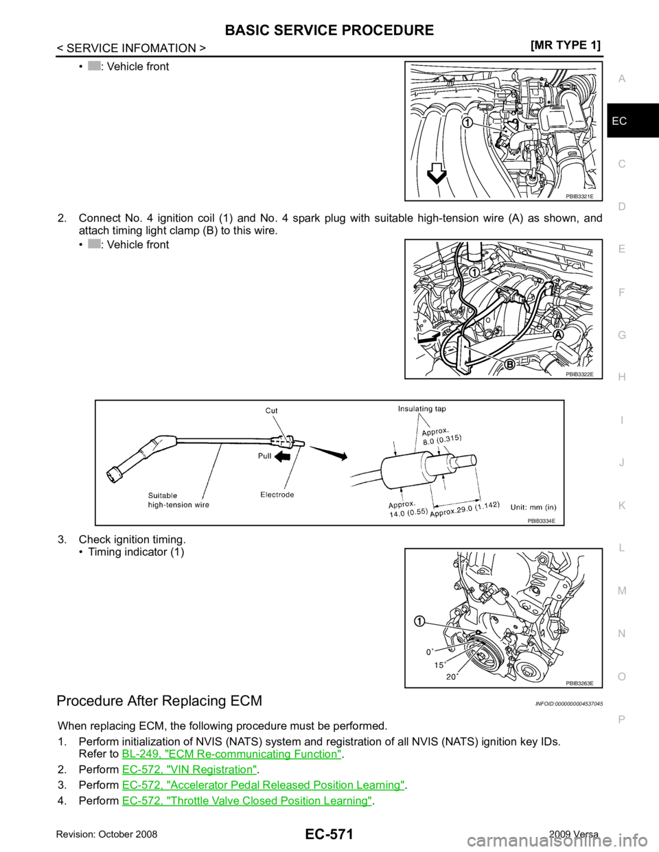
Method B
1. Remove No. 4 ignition coil (1). PBIB3263E
Page 1927 of 4331

EC
NP
O
• : Vehicle front
2. Connect No. 4 ignition coil (1) and No. 4 spark plug with suitable high-tension wire (A) as shown, and attach timing light clamp (B) to this wire.
• : Vehicle front
3. Check ignition timing. • Timing indicator (1)
Procedure After Replacing ECM INFOID:0000000004537045
When replacing ECM, the following procedure must be performed.
1. Perform initialization of NVIS (NATS) system and registration of all NVIS (NATS) ignition key IDs.
Refer to BL-249, " ECM Re-communicating Function " .
2. Perform EC-572, " VIN Registration " .
3. Perform EC-572, " Accelerator Pedal Released Position Learning " .
4. Perform EC-572, " Throttle Valve Closed Position Learning " . PBIB3322E
PBIB3263E
Page 1929 of 4331
![NISSAN LATIO 2009 Service Repair Manual EC
NP
O
[Air conditioner, headlamp, rear window defogger]
On vehicles equipped with daytime light systems, if the parking brake is applied before the engine is
started the headlamp will not be illumi NISSAN LATIO 2009 Service Repair Manual EC
NP
O
[Air conditioner, headlamp, rear window defogger]
On vehicles equipped with daytime light systems, if the parking brake is applied before the engine is
started the headlamp will not be illumi](/manual-img/5/57359/w960_57359-1928.png)
EC
NP
O
[Air conditioner, headlamp, rear window defogger]
On vehicles equipped with daytime light systems, if the parking brake is applied before the engine is
started the headlamp will not be illuminated.
• Steering wheel: Neutral (Straight-ahead position)
• Vehicle speed: Stopped
• Transmission: Warmed-up
- Models with CONSULT-III (A/T and CVT models)
• Drive vehicle until “FLUID TEMP SE” in “DATA MONI TOR” mode of “A/T” or “CVT” system indicates less
than 0.9V.
- Models without CONSULT-III (A/T and CVT models) and M/T models
• Drive vehicle for 10 minutes.
OPERATION PROCEDURE
With CONSULT-III
1. Perform EC-572, " Accelerator Pedal Released Position Learning " .
2. Perform EC-572, " Throttle Valve Closed Position Learning " .
3. Start engine and warm it up to normal operating temperature.
4. Check that all items listed under the topic PREP ARATION (previously mentioned) are in good order.
5. Select “IDLE AIR VOL LEA RN” in “WORK SUPPORT” mode.
6. Touch “START” and wait 20 seconds.
7. Make sure that “CMPLT” is displayed on CONSULT-III screen. If “CMPLT” is not displayed, Idle Air Vol-
ume Learning will not be carried out successfully. In this case, find the cause of the incident by referring to
the DIAGNOSTIC PROCEDURE below.
8. Rev up the engine two or three times and make sure that idle speed and ignition timing are within the specifications.
Refer to EC-566, " Basic Inspection " .
Without CONSULT-III
NOTE:
• It is better to count the time accurately with a clock.
• It is impossible to switch the di agnostic mode when an accelerator pedal position sensor circuit has
a malfunction.
1. Perform EC-572, " Accelerator Pedal Released Position Learning " .
2. Perform EC-572, " Throttle Valve Closed Position Learning " .
3. Start engine and warm it up to normal operating temperature.
4. Check that all items listed under the topic PREP ARATION (previously mentioned) are in good order.
5. Turn ignition switch OFF and wait at least 10 seconds.
6. Confirm that accelerator pedal is fully releas ed, turn ignition switch ON and wait 3 seconds.
7. Repeat the following procedure quick ly five times within 5 seconds.
a. Fully depress the accelerator pedal.
b. Fully release the accelerator pedal.
8. Wait 7 seconds, fully depress the accelerator pedal and keep it for approx. 20 seconds until the MIL stops
blinking and turned ON.
9. Fully release the accelerator pedal within 3 seconds after the MIL turned ON.
10. Start engine and let it idle.
Page 1931 of 4331

EC
NP
O
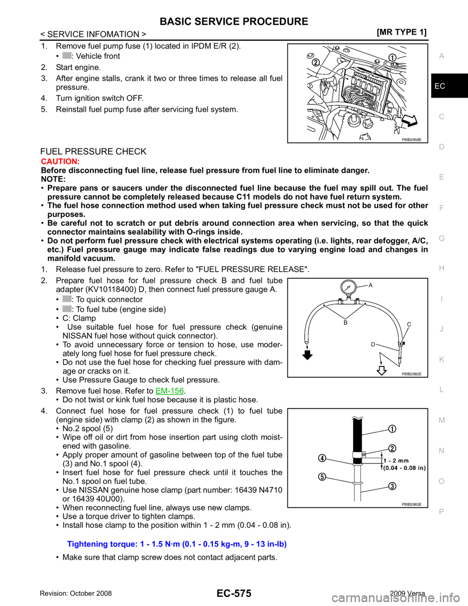
1. Remove fuel pump fuse (1) located in IPDM E/R (2).
• : Vehicle front
2. Start engine.
3. After engine stalls, crank it two or three times to release all fuel pressure.
4. Turn ignition switch OFF.
5. Reinstall fuel pump fuse after servicing fuel system.
FUEL PRESSURE CHECK CAUTION:
Before disconnecting fuel line, release fuel pressure from fuel line to eliminate danger.
NOTE:
• Prepare pans or saucers under the disconnected fuel line because the fuel may spill out. The fuel
pressure cannot be completely released because C11 models do not have fuel return system.
• The fuel hose connection method u sed when taking fuel pressure check must not be used for other
purposes.
• Be careful not to scratch or put debris around connection area when servicing, so that the quick
connector maintains sealability with O-rings inside.
• Do not perform fuel pressure check with electrical syst ems operating (i.e. lights, rear defogger, A/C,
etc.) Fuel pressure gauge may indicate false readin gs due to varying engine load and changes in
manifold vacuum.
1. Release fuel pressure to zero. Refer to "FUEL PRESSURE RELEASE".
2. Prepare fuel hose for fuel pressure check B and fuel tube adapter (KV10118400) D, then connect fuel pressure gauge A.
• : To quick connector
• : To fuel tube (engine side)
• C: Clamp
• Use suitable fuel hose for fuel pressure check (genuine
NISSAN fuel hose without quick connector).
• To avoid unnecessary force or tension to hose, use moder- ately long fuel hose for fuel pressure check.
• Do not use the fuel hose for checking fuel pressure with dam- age or cracks on it.
• Use Pressure Gauge to check fuel pressure.
3. Remove fuel hose. Refer to EM-156 .
• Do not twist or kink fuel hose because it is plastic hose.
4. Connect fuel hose for fuel pressure check (1) to fuel tube (engine side) with clamp (2) as shown in the figure.
• No.2 spool (5)
• Wipe off oil or dirt from hose insertion part using cloth moist-
ened with gasoline.
• Apply proper amount of gasoline between top of the fuel tube (3) and No.1 spool (4).
• Insert fuel hose for fuel pressure check until it touches the No.1 spool on fuel tube.
• Use NISSAN genuine hose clamp (part number: 16439 N4710
or 16439 40U00).
• When reconnecting fuel line, always use new clamps.
• Use a torque driver to tighten clamps.
• Install hose clamp to the positi on within 1 - 2 mm (0.04 - 0.08 in).
• Make sure that clamp screw does not contact adjacent parts.