2009 NISSAN LATIO light
[x] Cancel search: lightPage 1870 of 4331
![NISSAN LATIO 2009 Service Repair Manual EC-514< SERVICE INFOMATION >
[MR TYPE 1]
PRECAUTIONS
• Keep engine control system parts and harness dry.
• Before replacing ECM, perform “ECM Terminals and Refer-
ence Value” inspecti NISSAN LATIO 2009 Service Repair Manual EC-514< SERVICE INFOMATION >
[MR TYPE 1]
PRECAUTIONS
• Keep engine control system parts and harness dry.
• Before replacing ECM, perform “ECM Terminals and Refer-
ence Value” inspecti](/manual-img/5/57359/w960_57359-1869.png)
EC-514< SERVICE INFOMATION >
[MR TYPE 1]
PRECAUTIONS
• Keep engine control system parts and harness dry.
• Before replacing ECM, perform “ECM Terminals and Refer-
ence Value” inspection and m ake sure ECM functions prop-
erly. Refer to EC-597, " ECM Terminal and Reference Value " .
• Handle mass air flow sensor carefully to avoid damage.
• Do not disassemble m ass air flow sensor.
• Do not clean mass air flow senso r with any type of detergent.
• Do not disassemble electric throttle control actuator.
• Even a slight leak in the ai r intake system can cause serious
incidents.
• Do not shock or jar the camshaft position sensor (PHASE),
crankshaft position sensor (POS).
• After performing each TROUBLE DIAGNOSIS, perform DTC
Confirmation Procedure or Overall Function Check.
The DTC should not be displ ayed in the DTC Confirmation
Procedure if the repair is co mpleted. The Overall Function
Check should be a good result if the repair is completed.
• When measuring ECM signals with a circuit tester, never allow
the two tester probes to contact.
Accidental contact of probes will cause a short circuit and
damage the ECM power transistor.
• Do not use ECM ground termina ls when measuring input/out-
put voltage. Doing so may result in damage to the ECM's tran-
sistor. Use a ground other than ECM terminals, such as the
ground. MEF040D
SEF217U
SEF348N
Page 1897 of 4331
EC
NP
O
ON BOARD DIAGNOSTIC (OBD) SYSTEM
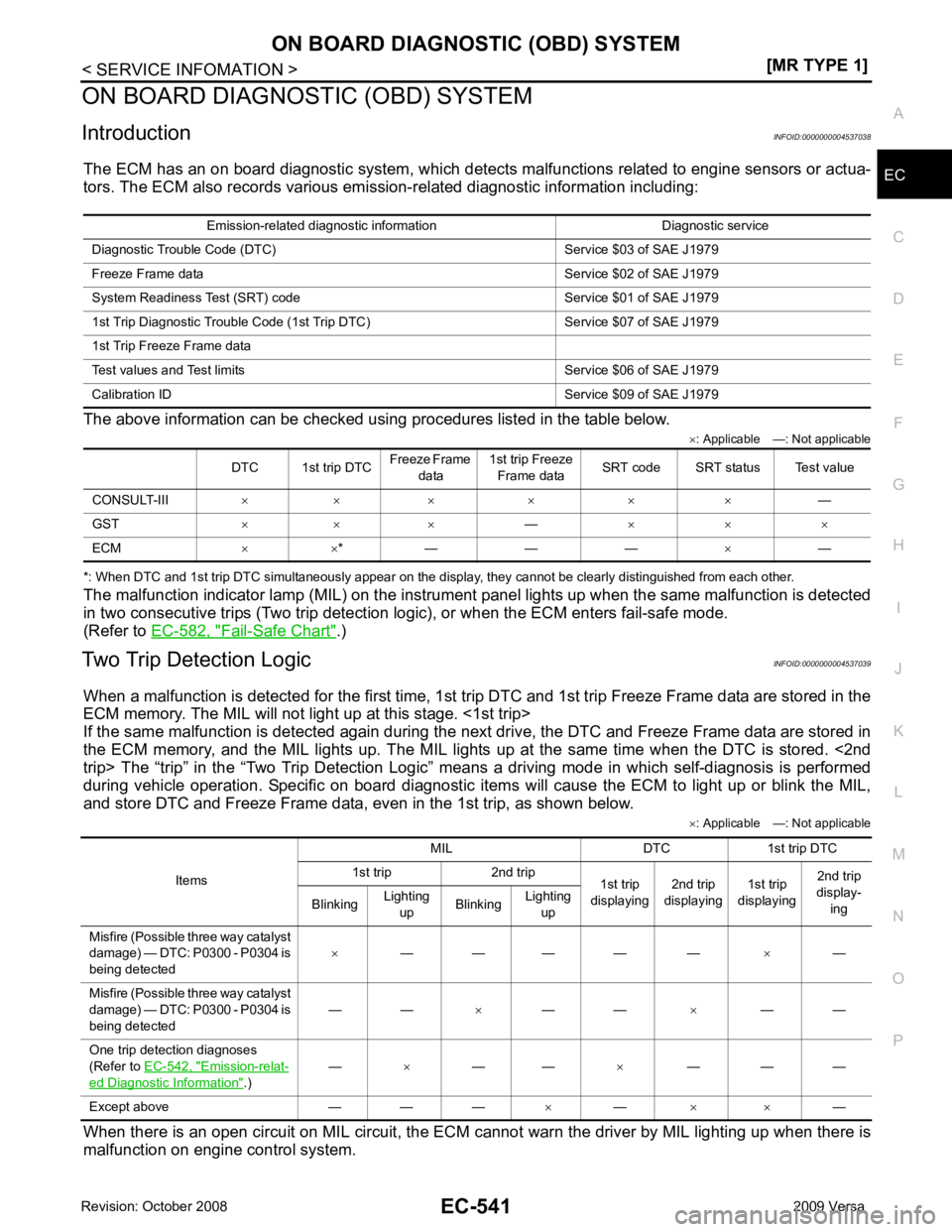
Introduction INFOID:0000000004537038
The ECM has an on board diagnostic system, which detects malfunctions related to engine sensors or actua-
tors. The ECM also records various emis sion-related diagnostic information including:
The above information can be checked using procedures listed in the table below. ×: Applicable —: Not applicable
*: When DTC and 1st trip DTC simultaneously appear on the display, they cannot be clearly distinguished from each other.
The malfunction indicator lamp (MIL) on the instrument panel lights up when the same malfunction is detected
in two consecutive trips (Two trip detection logic), or when the ECM enters fail-safe mode.
(Refer to EC-582, " Fail-Safe Chart " .)
Two Trip Detection Logic INFOID:0000000004537039
When a malfunction is detected for the first time, 1st tr ip DTC and 1st trip Freeze Frame data are stored in the
ECM memory. The MIL will not light up at this stage. <1st trip>
If the same malfunction is detected again during the next drive, the DTC and Freeze Frame data are stored in
the ECM memory, and the MIL lights up. The MIL lights up at the same time when the DTC is stored. <2nd
trip> The “trip” in the “Two Trip Detection Logic” m eans a driving mode in which self-diagnosis is performed
during vehicle operation. Specific on board diagnostic item s will cause the ECM to light up or blink the MIL,
and store DTC and Freeze Frame data, even in the 1st trip, as shown below.
×: Applicable —: Not applicable
When there is an open circuit on MIL circuit, the ECM c annot warn the driver by MIL lighting up when there is
malfunction on engine control system. Emission-related diagnostic information Diagnostic service
Diagnostic Tr ouble Code (DTC) Service $03 of SAE J1979
Freeze Frame data Service $02 of SAE J1979
System Readiness Test (SRT) code Service $01 of SAE J1979
1st Trip Diagnostic Trou ble Code (1st Trip DTC) Service $07 of SAE J1979
1st Trip Freeze Frame data
Test values and Test limi ts Service $06 of SAE J1979
Calibration ID Servic e $09 of SAE J1979
DTC 1st trip DTC Freeze Frame
data 1st trip Freeze
Frame data SRT code SRT status Test value
CONSULT-III × × × × × × —
GST × × × —× × ×
ECM × ×* — — — ×— Items
MIL DTC 1st trip DTC
1st trip 2nd trip 1st trip
displaying 2nd trip
displaying 1st trip
displaying 2nd trip
display-
ing
Blinking Lighting
up Blinking
Lighting
up
Misfire (Possible three way catalyst
damage) — DTC: P0300 - P0304 is
being detected ×
— — — — — ×—
Misfire (Possible three way catalyst
damage) — DTC: P0300 - P0304 is
being detected — —
×— — ×— —
One trip detection diagnoses
(Refer to EC-542, " Emission-relat-
ed Diagnostic Information " .)
—
×— — ×— — —
Except above — — — ×— × × —
Page 1898 of 4331
Items
(CONSULT-III screen terms) DTC*
1
SRT code Trip MIL lighting up Reference page
CONSULT-III
GST* 2
ECM*3
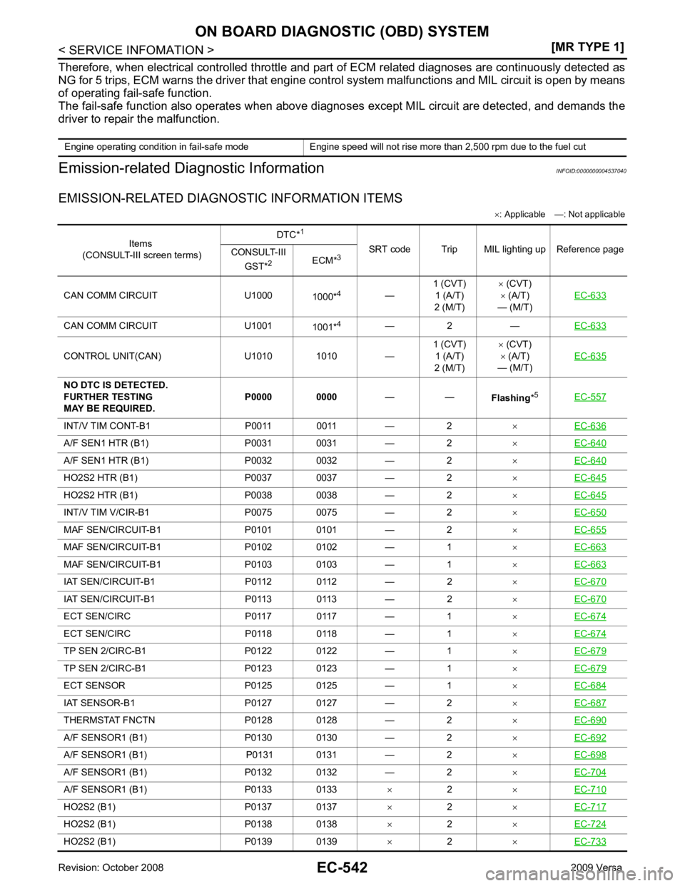
CAN COMM CIRCUIT U1000 1000*4
—1 (CVT)
1 (A/T)
2 (M/T) ×
(CVT)
× (A/T)
— (M/T) EC-633CAN COMM CIRCUIT U1001
1001*4
— 2 — EC-633CONTROL UNIT(CAN) U1010 1010 —
1 (CVT)
1 (A/T)
2 (M/T) ×
(CVT)
× (A/T)
— (M/T) EC-635INT/V TIM CONT-B1 P0011 0011 — 2
×EC-636 A/F SEN1 HTR (B1) P0031 0031 — 2
×EC-640 A/F SEN1 HTR (B1) P0032 0032 — 2
×EC-640 HO2S2 HTR (B1) P0037 0037 — 2
×EC-645 HO2S2 HTR (B1) P0038 0038 — 2
×EC-645 INT/V TIM V/CIR-B1 P0075 0075 — 2
×EC-650 MAF SEN/CIRCUIT-B1 P0101 0101 — 2
×EC-655 MAF SEN/CIRCUIT-B1 P0102 0102 — 1
×EC-663 MAF SEN/CIRCUIT-B1 P0103 0103 — 1
×EC-663 IAT SEN/CIRCUIT-B1 P0112 0112 — 2
×EC-670 IAT SEN/CIRCUIT-B1 P0113 0113 — 2
×EC-670 ECT SEN/CIRC P0117 0117 — 1
×EC-674 ECT SEN/CIRC P0118 0118 — 1
×EC-674 TP SEN 2/CIRC-B1 P0122 0122 — 1
×EC-679 TP SEN 2/CIRC-B1 P0123 0123 — 1
×EC-679 ECT SENSOR P0125 0125 — 1
×EC-684 IAT SENSOR-B1 P0127 0127 — 2
×EC-687 THERMSTAT FNCTN P0128 0128 — 2
×EC-690 A/F SENSOR1 (B1) P0130 0130 — 2
×EC-692 A/F SENSOR1 (B1) P0131 0131 — 2
×EC-698 A/F SENSOR1 (B1) P0132 0132 — 2
×EC-704 A/F SENSOR1 (B1) P0133 0133
×2 ×EC-710 HO2S2 (B1) P0137 0137
×2 ×EC-717 HO2S2 (B1) P0138 0138
×2 ×EC-724 HO2S2 (B1) P0139 0139
×2 ×EC-733
Page 1899 of 4331
EC
NP
O
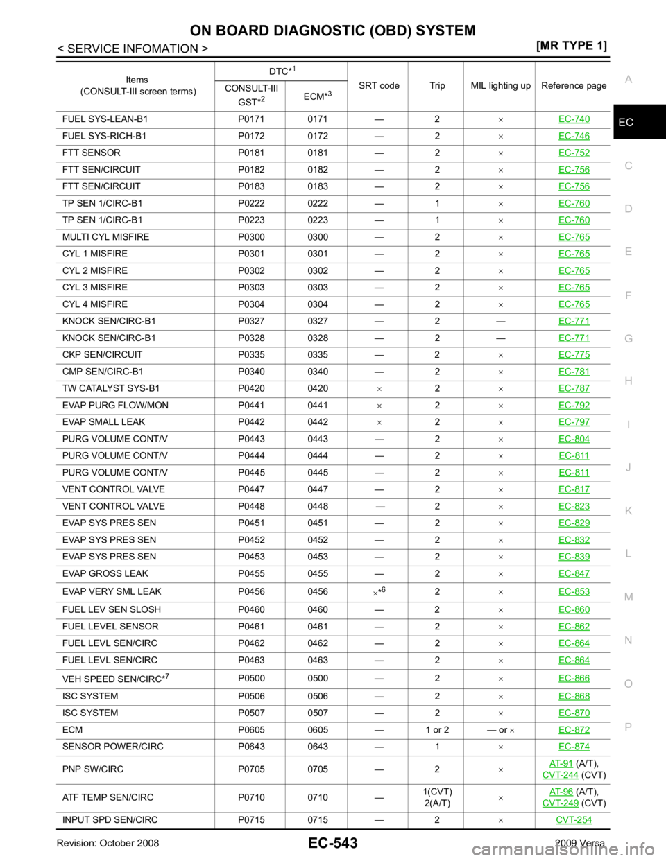
FUEL SYS-LEAN-B1 P0171 0171 — 2
×EC-740 FUEL SYS-RICH-B1 P0172 0172 — 2
×EC-746 FTT SENSOR P0181 0181 — 2
×EC-752 FTT SEN/CIRCUIT P0182 0182 — 2
×EC-756 FTT SEN/CIRCUIT P0183 0183 — 2
×EC-756 TP SEN 1/CIRC-B1 P0222 0222 — 1
×EC-760 TP SEN 1/CIRC-B1 P0223 0223 — 1
×EC-760 MULTI CYL MISFIRE P0300 0300 — 2
×EC-765 CYL 1 MISFIRE P0301 0301 — 2
×EC-765 CYL 2 MISFIRE P0302 0302 — 2
×EC-765 CYL 3 MISFIRE P0303 0303 — 2
×EC-765 CYL 4 MISFIRE P0304 0304 — 2
×EC-765 KNOCK SEN/CIRC-B1 P0327 0327 — 2 —
EC-771KNOCK SEN/CIRC-B1 P0328 0328 — 2 —
EC-771CKP SEN/CIRCUIT P0335 0335 — 2
×EC-775 CMP SEN/CIRC-B1 P0340 0340 — 2
×EC-781 TW CATALYST SYS-B1 P0420 0420
× 2 ×EC-787 EVAP PURG FLOW/MON P0441 0441
×2 ×EC-792 EVAP SMALL LEAK P0442 0442
×2 ×EC-797 PURG VOLUME CONT/V P0443 0443 — 2
×EC-804 PURG VOLUME CONT/V P0444 0444 — 2
×EC-811 PURG VOLUME CONT/V P0445 0445 — 2
×EC-811 VENT CONTROL VALVE P0447 0447 — 2
×EC-817 VENT CONTROL VALVE P0448 0448 — 2
×EC-823 EVAP SYS PRES SEN P0451 0451 — 2
×EC-829 EVAP SYS PRES SEN P0452 0452 — 2
×EC-832 EVAP SYS PRES SEN P0453 0453 — 2
×EC-839 EVAP GROSS LEAK P0455 0455 — 2
×EC-847 EVAP VERY SML LEAK P0456 0456
×*6
2 ×EC-853 FUEL LEV SEN SLOSH P0460 0460 — 2
×EC-860 FUEL LEVEL SEN
SOR P0461 0461 — 2 ×EC-862 FUEL LEVL SEN/C
IRC P0462 0462 — 2 ×EC-864 FUEL LEVL SEN/C
IRC P0463 0463 — 2 ×EC-864 VEH SPEED SEN/CIRC*
7
P0500 0500 — 2 ×EC-866 ISC SYSTEM P0506 0506 — 2
×EC-868 ISC SYSTEM P0507 0507 — 2
×EC-870 ECM P0605 0605 — 1 or 2 — or
×EC-872 SENSOR POWER/CIRC P0643 0643 — 1
×EC-874 PNP SW/CIRC P0705 0705 — 2
×AT-91 (A/T),
CVT-244 (CVT)
ATF TEMP SEN/CIRC P0710 0710 — 1(CVT)
2(A/T) ×
AT-96 (A/T),
CVT-249 (CVT)
INPUT SPD SEN/CIRC P0715 0715 — 2 ×CVT-254 Items
(CONSULT-III screen terms) DTC*
1
SRT code Trip MIL lighting up Reference page
CONSULT-III
GST* 2
ECM*3
Page 1900 of 4331
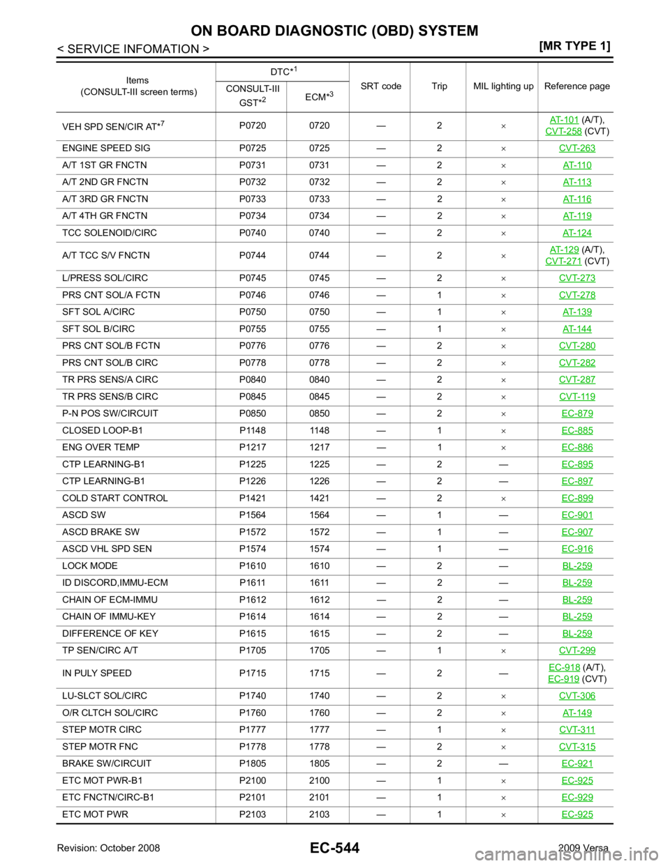
(A/T),
CVT-258 (CVT)
ENGINE SPEED SIG P0725 0725 — 2 ×CVT-263 A/T 1ST GR FNCTN P0731 0731 — 2
×AT-110 A/T 2ND GR FNCTN P0732 0732 — 2
×AT-113 A/T 3RD GR FNCTN P0733 0733 — 2
×AT-116 A/T 4TH GR FNCTN P0734 0734 — 2
×AT-119 TCC SOLENOID/CIRC P0740 0740 — 2
×AT-124 A/T TCC S/V FNCTN P0744 0744 — 2
×AT-129 (A/T),
CVT-271 (CVT)
L/PRESS SOL/CIRC P0745 0745 — 2 ×CVT-273 PRS CNT SOL/A FCTN P0746 0746 — 1
×CVT-278 SFT SOL A/CIRC P0750 0750 — 1
×AT-139 SFT SOL B/CIRC P0755 0755 — 1
×AT-144 PRS CNT SOL/B FCTN P0776 0776 — 2
×CVT-280 PRS CNT SOL/B CIRC P0778 0778 — 2
×CVT-282 TR PRS SENS/A CIRC P0840 0840 — 2
×CVT-287 TR PRS SENS/B CIRC P0845 0845 — 2
×CVT-119 P-N POS SW/CIRCUIT P0850 0850 — 2
×EC-879 CLOSED LOOP-B1 P1148 1148 — 1
×EC-885 ENG OVER TEMP P1217 1217 — 1
×EC-886 CTP LEARNING-B1 P1225 1225 — 2 —
EC-895CTP LEARNING-B1 P1226 1226 — 2 —
EC-897COLD START CONTROL P1421 1421 — 2
×EC-899 ASCD SW P1564 1564 — 1 —
EC-901ASCD BRAKE SW P1572 1572 — 1 —
EC-907ASCD VHL SPD SEN P1574 1574 — 1 —
EC-916LOCK MODE P1610 1610 — 2 —
BL-259ID DISCORD,IMMU-ECM P1611 1611 — 2 —
BL-259CHAIN OF ECM-IMMU P1612 1612 — 2 —
BL-259CHAIN OF IMMU-KEY P1614 1614 — 2 —
BL-259DIFFERENCE OF KEY P1615 1615 — 2 —
BL-259TP SEN/CIRC A/T P1705 1705 — 1
×CVT-299 IN PULY SPEED P1715 1715 — 2 —
EC-918 (A/T),
EC-919 (CVT)
LU-SLCT SOL/CIRC P1740 1740 — 2 ×CVT-306 O/R CLTCH SOL/CIRC P1760 1760 — 2
×AT-149 STEP MOTR CIRC P1777 1777 — 1
×CVT-311 STEP MOTR FNC P1778 1778 — 2
×CVT-315 BRAKE SW/CIRCUIT P1805 1805 — 2 —
EC-921ETC MOT PWR-B1 P2100 2100 — 1
×EC-925 ETC FNCTN/CIRC-B1 P2101 2101 — 1
×EC-929 ETC MOT PWR P2103 2103 — 1
×EC-925 Items
(CONSULT-III screen terms) DTC*
1
SRT code Trip MIL lighting up Reference page
CONSULT-III
GST* 2
ECM*3
Page 1901 of 4331
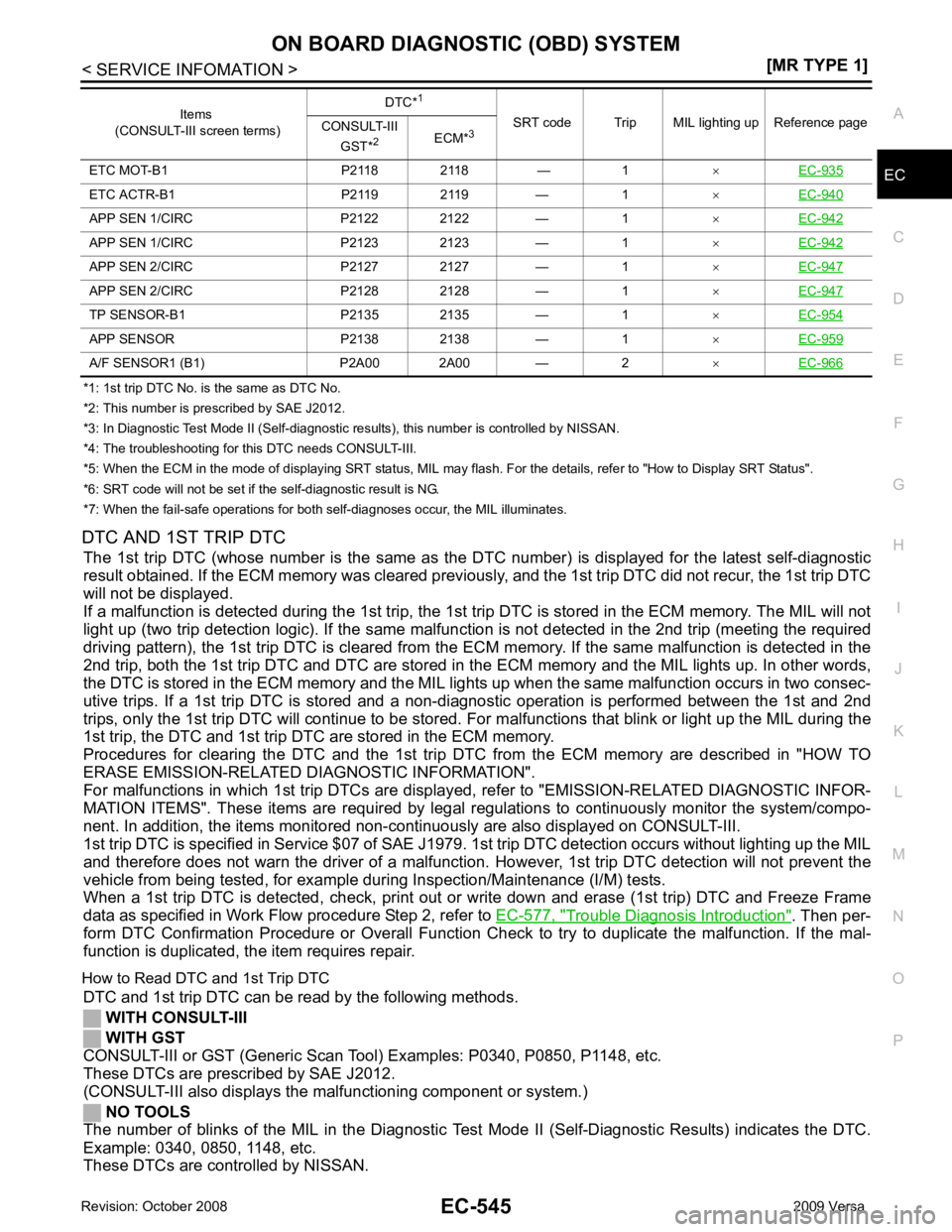
EC
NP
O
*1: 1st trip DTC No. is
the same as DTC No.
*2: This number is prescribed by SAE J2012.
*3: In Diagnostic Test Mode II (Self-diagnostic results), this number is controlled by NISSAN.
*4: The troubleshooting for this DTC needs CONSULT-III.
*5: When the ECM in the mode of displaying SRT status, MIL may flash. For the details, refer to "How to Display SRT Status".
*6: SRT code will not be set if the self-diagnostic result is NG.
*7: When the fail-safe operations for both self-diagnoses occur, the MIL illuminates.
DTC AND 1ST TRIP DTC The 1st trip DTC (whose number is the same as the DT C number) is displayed for the latest self-diagnostic
result obtained. If the ECM memory was cleared previously , and the 1st trip DTC did not recur, the 1st trip DTC
will not be displayed.
If a malfunction is detected during the 1st trip, the 1st trip DTC is stored in the ECM memory. The MIL will not
light up (two trip detection logic). If the same malfunc tion is not detected in the 2nd trip (meeting the required
driving pattern), the 1st trip DTC is cleared from the ECM memory. If the same malfunction is detected in the
2nd trip, both the 1st trip DTC and DTC are stored in t he ECM memory and the MIL lights up. In other words,
the DTC is stored in the ECM memory and the MIL light s up when the same malfunction occurs in two consec-
utive trips. If a 1st trip DTC is stored and a non-diagnostic operation is performed between the 1st and 2nd
trips, only the 1st trip DTC will continue to be stored. Fo r malfunctions that blink or light up the MIL during the
1st trip, the DTC and 1st trip DTC are stored in the ECM memory.
Procedures for clearing the DTC and the 1st trip DT C from the ECM memory are described in "HOW TO
ERASE EMISSION-RELATED DIAGNOSTIC INFORMATION".
For malfunctions in which 1st trip DTCs are displa yed, refer to "EMISSION-RELATED DIAGNOSTIC INFOR-
MATION ITEMS". These items are required by legal r egulations to continuously monitor the system/compo-
nent. In addition, the items monitored non-cont inuously are also displayed on CONSULT-III.
1st trip DTC is specified in Service $07 of SAE J1979. 1st trip DTC detection occurs without lighting up the MIL
and therefore does not warn the driver of a malfunction. However, 1st trip DTC detection will not prevent the
vehicle from being tested, for example during Inspection/Maintenance (I/M) tests.
When a 1st trip DTC is detected, check, print out or write down and erase (1st trip) DTC and Freeze Frame
data as specified in Work Flow procedure Step 2, refer to EC-577, " Trouble Diagnosis Introduction " . Then per-
form DTC Confirmation Procedure or Overall Function Che ck to try to duplicate the malfunction. If the mal-
function is duplicated, the item requires repair.
How to Read DTC and 1st Trip DTC DTC and 1st trip DTC can be read by the following methods.
WITH CONSULT-III
WITH GST
CONSULT-III or GST (Generic Scan Tool ) Examples: P0340, P0850, P1148, etc.
These DTCs are prescribed by SAE J2012.
(CONSULT-III also displays the malfunctioning component or system.)
NO TOOLS
The number of blinks of the MIL in the Diagnostic Test Mode II (Self-Diagnostic Results) indicates the DTC.
Example: 0340, 0850, 1148, etc.
These DTCs are controlled by NISSAN. ETC MOT-B1 P2118 2118 — 1
×EC-935 ETC ACTR-B1 P2119 2119 — 1
×EC-940 APP SEN 1/CIRC P2122 2122 — 1
×EC-942 APP SEN 1/CIRC P2123 2123 — 1
×EC-942 APP SEN 2/CIRC P2127 2127 — 1
×EC-947 APP SEN 2/CIRC P2128 2128 — 1
×EC-947 TP SENSOR-B1 P2135 2135 — 1
×EC-954 APP SENSOR P2138 2138 — 1
×EC-959 A/F SENSOR1 (B1) P2A00 2A00 — 2
×EC-966 Items
(CONSULT-III screen terms) DTC*
1
SRT code Trip MIL lighting up Reference page
CONSULT-III
GST* 2
ECM*3
Page 1905 of 4331
![NISSAN LATIO 2009 Service Repair Manual ON BOARD DIAGNOSTIC (OBD) SYSTEM
EC-549
< SERVICE INFOMATION >
[MR TYPE 1] C
D E
F
G H
I
J
K L
M A EC
NP
O
Selecting “SRT STATUS” in “DTC & SR
T ONFIRMATION” mode with CONSULT-III.
For items NISSAN LATIO 2009 Service Repair Manual ON BOARD DIAGNOSTIC (OBD) SYSTEM
EC-549
< SERVICE INFOMATION >
[MR TYPE 1] C
D E
F
G H
I
J
K L
M A EC
NP
O
Selecting “SRT STATUS” in “DTC & SR
T ONFIRMATION” mode with CONSULT-III.
For items](/manual-img/5/57359/w960_57359-1904.png)
ON BOARD DIAGNOSTIC (OBD) SYSTEM
EC-549
< SERVICE INFOMATION >
[MR TYPE 1] C
D E
F
G H
I
J
K L
M A EC
NP
O
Selecting “SRT STATUS” in “DTC & SR
T ONFIRMATION” mode with CONSULT-III.
For items whose SRT codes are set, a “CMPLT” is di splayed on the CONSULT-III screen; for items whose
SRT codes are not set, “INCMP” is displayed.
NOTE:
Though displayed on the CONSULT-III scr een, “HO2S HTR” is not SRT item.
WITH GST
Selecting Service $01 with GST (Generic Scan Tool)
NO TOOLS
A SRT code itself can not be displayed while only SRT status can be.
1. Turn ignition switch ON and wait 20 seconds.
2. SRT status is indicated as shown below. • When all SRT codes are set, MIL lights up continuously.
• When any SRT codes are not set, MIL will flash periodically for 10 seconds.
How to Set SRT Code To set all SRT codes, self-diagnosis for the items indicated above must be performed one or more times. Each
diagnosis may require a long period of actual driving under various conditions.
WITH CONSULT-III
Perform corresponding DTC Confirmation Procedure one by one based on Performance Priority in the table
on "SRT Item".
WITHOUT CONSULT-III
The most efficient driving pattern in which SRT codes can be properly set is explained on the next page. The
driving pattern should be performed one or more times to set all SRT codes. PBIB2317E
Page 1913 of 4331
![NISSAN LATIO 2009 Service Repair Manual ON BOARD DIAGNOSTIC (OBD) SYSTEM
EC-557
< SERVICE INFOMATION >
[MR TYPE 1] C
D E
F
G H
I
J
K L
M A EC
NP
O
4. Touch "ERASE". (The DTC in the ECM will be erased.)
With GST
NOTE:
If the ignition switch NISSAN LATIO 2009 Service Repair Manual ON BOARD DIAGNOSTIC (OBD) SYSTEM
EC-557
< SERVICE INFOMATION >
[MR TYPE 1] C
D E
F
G H
I
J
K L
M A EC
NP
O
4. Touch "ERASE". (The DTC in the ECM will be erased.)
With GST
NOTE:
If the ignition switch](/manual-img/5/57359/w960_57359-1912.png)
ON BOARD DIAGNOSTIC (OBD) SYSTEM
EC-557
< SERVICE INFOMATION >
[MR TYPE 1] C
D E
F
G H
I
J
K L
M A EC
NP
O
4. Touch "ERASE". (The DTC in the ECM will be erased.)
With GST
NOTE:
If the ignition switch stays ON after repair work, be sure to turn ignition switch OFF once. Wait at least 10 sec-
onds and then turn it ON (engine stopped) again.
1. Select Service $04 with GST.
No Tools
NOTE:
If the ignition switch stays ON after repair work, be sure to turn ignition switch OFF once. Wait at least 10 sec-
onds and then turn it ON (engine stopped) again.
1. Erase DTC in ECM. Refer to How to Erase Diagnostic Test Mode II (Self-diagnostic Results).
• If the battery is disconnected, the emission-relate d diagnostic information will be lost within 24
hours.
• The following data are cleared when the ECM memory is erased.
- Diagnostic trouble codes
- 1st trip diagnostic trouble codes
- Freeze frame data
- 1st trip freeze frame data
- System readiness test (SRT) codes
- Test values
Malfunction Indicator Lamp (MIL) INFOID:0000000004537041
DESCRIPTION The MIL is located on the instrument panel.
1. The MIL will light up when the ignition switch is turned ON with- out the engine running. This is a bulb check.
If the MIL does not light up, refer to DI-20 or see
EC-1010 .
2. When the engine is start ed, the MIL should go off.
If the MIL remains on, the on board diagnostic system has
detected an engine system malfunction.
ON BOARD DIAGNOSTIC SYSTEM FUNCTION The on board diagnostic system has the following three functions. SEF217U