Page 3975 of 4331
Application MR18DE - TYPE
1 and HR16DE MR18DE - TYPE 2
Compressor model Calsonic Kansei make CR-10 Calsonic Kansei make CSV511
Type NISSAN A/C System Oil Type R NISSAN A/C System Oil Type S
Capacity
m (US fl oz,
lmp fl oz) Total in system 120 (4.1, 4.2) 100 (3.4, 3.5)
Compressor (service
part) charging
amount Refer to
MTC-17, " Maintenance of Oil Quanti-
ty in Compressor " .
Refer to
MTC-17, " Maintenance of Oil
Quantity in Compressor " .
Type
HFC-134a (R-134a)
Capacity
kg (lb) 0.45
± 0.05 (0.99 ± 0.11)
Page 4040 of 4331
PG
N
O P
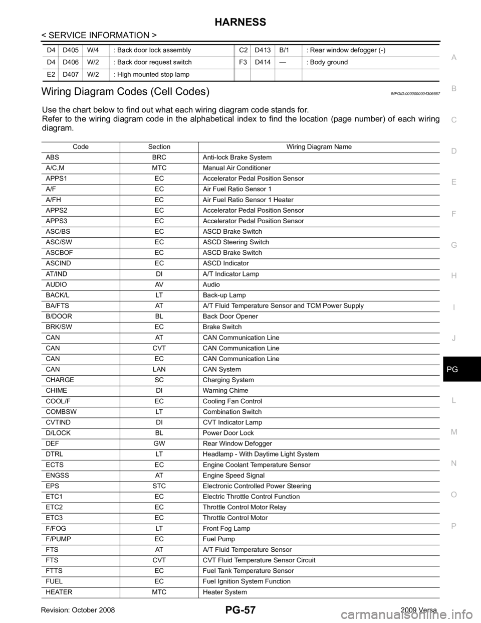
Wiring Diagram Codes (Cell Codes)
INFOID:0000000004306667
Use the chart below to find out what each wiring diagram code stands for.
Refer to the wiring diagram code in the alphabetical index to find the location (page number) of each wiring
diagram. D4 D405 W/4 : Back door lock assembly C2 D413 B/1 : Rear window defogger (-)
D4 D406 W/2 : Back door request switch F3 D414 — : Body ground
E2 D407 W/2 : High mounted stop lamp Code Section Wiring Diagram Name
ABS BRC Anti-lock Brake System
A/C,M MTC Manual Air Conditioner
APPS1 EC Accelerator Pe dal Position Sensor
A/F EC Air Fuel Ratio Sensor 1
A/FH EC Air Fuel Ratio Sensor 1 Heater
APPS2 EC Accelerator Pe dal Position Sensor
APPS3 EC Accelerator Pe dal Position Sensor
ASC/BS EC ASCD Brake Switch
ASC/SW EC ASCD Steering Switch
ASCBOF EC ASCD Brake Switch
ASCIND EC ASCD Indicator
AT/IND DI A/T Indicator Lamp
AUDIO AV Audio
BACK/L LT Back-up Lamp
BA/FTS AT A/T Fluid Temperature Sensor and TCM Power Supply
B/DOOR BL Back Door Opener
BRK/SW EC Brake Switch
CAN AT CAN Communication Line
CAN CVT CAN Comm unication Line
CAN EC CAN Communication Line
CAN LAN CAN System
CHARGE SC Charging System
CHIME DI Warning Chime
COOL/F EC Cooling Fan Control
COMBSW LT Combination Switch
CVTIND DI CVT Indicator Lamp
D/LOCK BL Power Door Lock
DEF GW Rear Window Defogger
DTRL LT Headlamp - Wi th Daytime Light System
ECTS EC Engine Coolant Temperature Sensor
ENGSS AT Engine Speed Signal
EPS STC Electronic Controlled Power Steering
ETC1 EC Electric Throttle Control Function
ETC2 EC Throttle Control Motor Relay
ETC3 EC Throttle Control Motor
F/FOG LT Front Fog Lamp
F/PUMP EC Fuel Pump
FTS AT A/T Fluid Temperature Sensor
FTS CVT CVT Fluid Temperature Sensor Circuit
FTTS EC Fuel Tank Temperature Sensor
FUEL EC Fuel Ignition System Function
HEATER MTC Heater System
Page 4137 of 4331
SC
N
O P
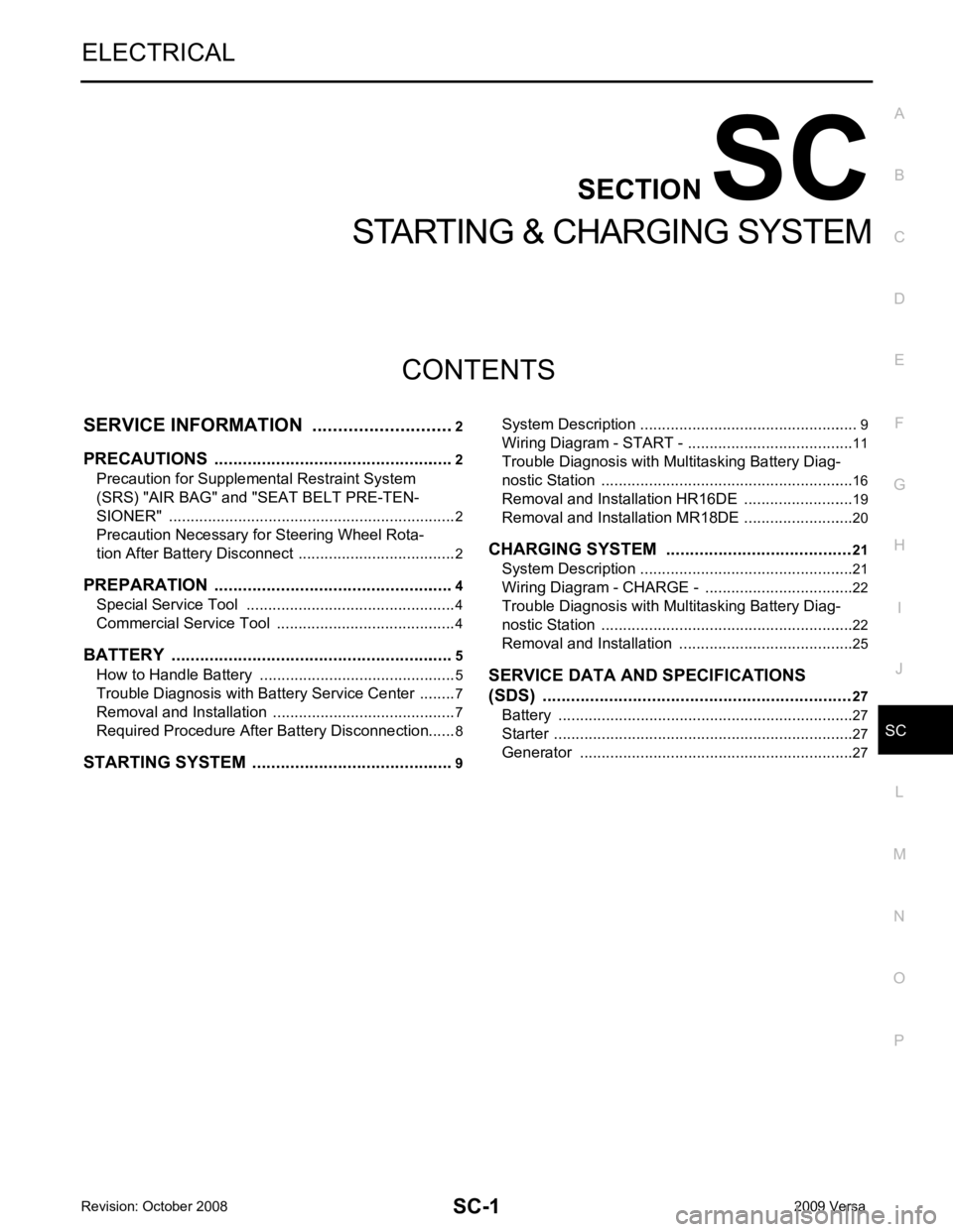
CONTENTS
STARTING & CHARGING SYSTEM
SERVICE INFORMATION .. ..........................2
PRECAUTIONS .............................................. .....2
Precaution for Supplemental Restraint System
(SRS) "AIR BAG" and "SEAT BELT PRE-TEN-
SIONER" ............................................................. ......
2
Precaution Necessary fo r Steering Wheel Rota-
tion After Battery Disconnect ............................... ......
2
PREPARATION .............................................. .....4
Special Service Tool ........................................... ......4
Commercial Service Tool .................................... ......4
BATTERY ....................................................... .....5
How to Handle Ba ttery ........................................ ......5
Trouble Diagnosis with Battery Service Center ... ......7
Removal and Installation ...........................................7
Required Procedure After Battery Disconnection ......8
STARTING SYSTEM ...................................... .....9 System Description ..............................................
.....9
Wiring Diagram - START - ................................... ....11
Trouble Diagnosis with Multitasking Battery Diag-
nostic Station ....................................................... ....
16
Removal and Installation HR16DE ...................... ....19
Removal and Installation MR18DE ...................... ....20
CHARGING SYSTEM ....................................... 21
System Description .............................................. ....21
Wiring Diagram - CHARGE - ............................... ....22
Trouble Diagnosis with Multitasking Battery Diag-
nostic Station ....................................................... ....
22
Removal and Installation ..................................... ....25
SERVICE DATA AND SPECIFICATIONS
(SDS) ................................................................. 27
Battery ................................................................. ....27
Starter .................................................................. ....27
Generator ............................................................ ....27
Page 4141 of 4331
SC
N
O P
BATTERY
How to Handle Battery INFOID:0000000004306818
CAUTION:
• If it becomes necessary to start the engine with a booster battery and jumper cables, use a 12-volt
booster battery.
• After connecting battery cables, ensure that they are tightly clamped to battery terminals for good
contact.
• Never add distilled water through the hole used to check specific gravity.
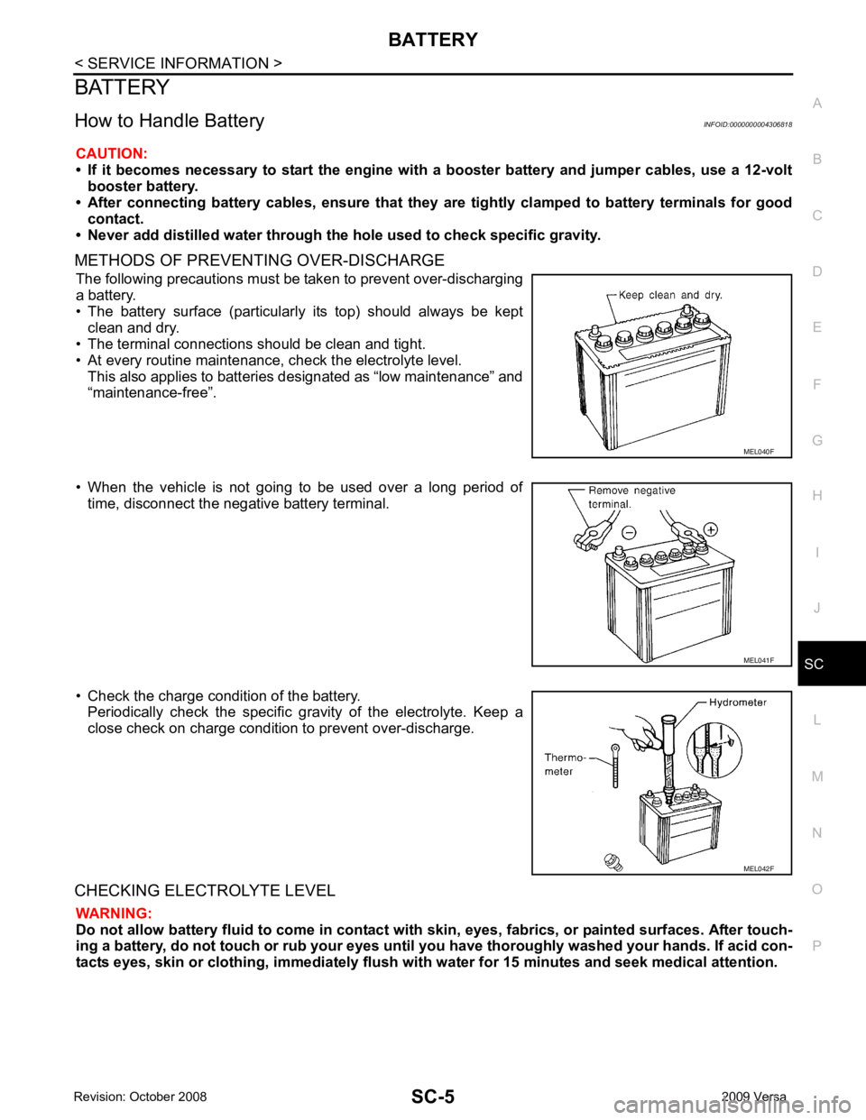
METHODS OF PREVENTING OVER-DISCHARGE The following precautions must be taken to prevent over-discharging
a battery.
• The battery surface (particularly its top) should always be kept clean and dry.
• The terminal connections should be clean and tight.
• At every routine maintenance, check the electrolyte level. This also applies to batteries designated as “low maintenance” and
“maintenance-free”.
• When the vehicle is not going to be used over a long period of time, disconnect the negative battery terminal.
• Check the charge condition of the battery. Periodically check the specific gr avity of the electrolyte. Keep a
close check on charge condition to prevent over-discharge.
CHECKING ELECTROLYTE LEVEL WARNING:
Do not allow battery fluid to come in contact with skin, eyes, fabrics, or painted surfaces. After touch-
ing a battery, do not touch or rub your eyes until yo u have thoroughly washed your hands. If acid con-
tacts eyes, skin or clothing, imme diately flush with water for 15 minutes and seek medical attention. MEL041F
Page 4143 of 4331
SC
N
O P
CHARGING THE BATTERY
CAUTION:
• Do not “quick charge” a fully discharged battery.
• Keep the battery away from open flame while it is being charged.
• When connecting the charger, connect the leads first, then turn on the charger. Do not turn on the
charger first, as this may cause a spark.
• If battery electrolyte temperature rises above 55 °C (131 °F), stop charging. Alw ays charge battery at a
temperature below 55 °C (131 °F).
Charging Rates
Do not charge at more than 50 ampere rate.
NOTE:
The ammeter reading on your battery charger will automat ically decrease as the battery charges. This indi-
cates that the voltage of the battery is increasing norma lly as the state of charge improves. The charging amps
indicated above refer to initial charge rate.
• If, after charging, the specific gravity of any two ce lls varies more than 0.050, the battery should be replaced.
Trouble Diagnosis with Battery Service Center INFOID:0000000004306819
For battery testing, use Battery Serv ice Center (J-48087). For details and operating instructions, refer to Tech-
nical Service Bulletin and/or Battery Service Center User Guide.
Removal and Installation INFOID:0000000004306820
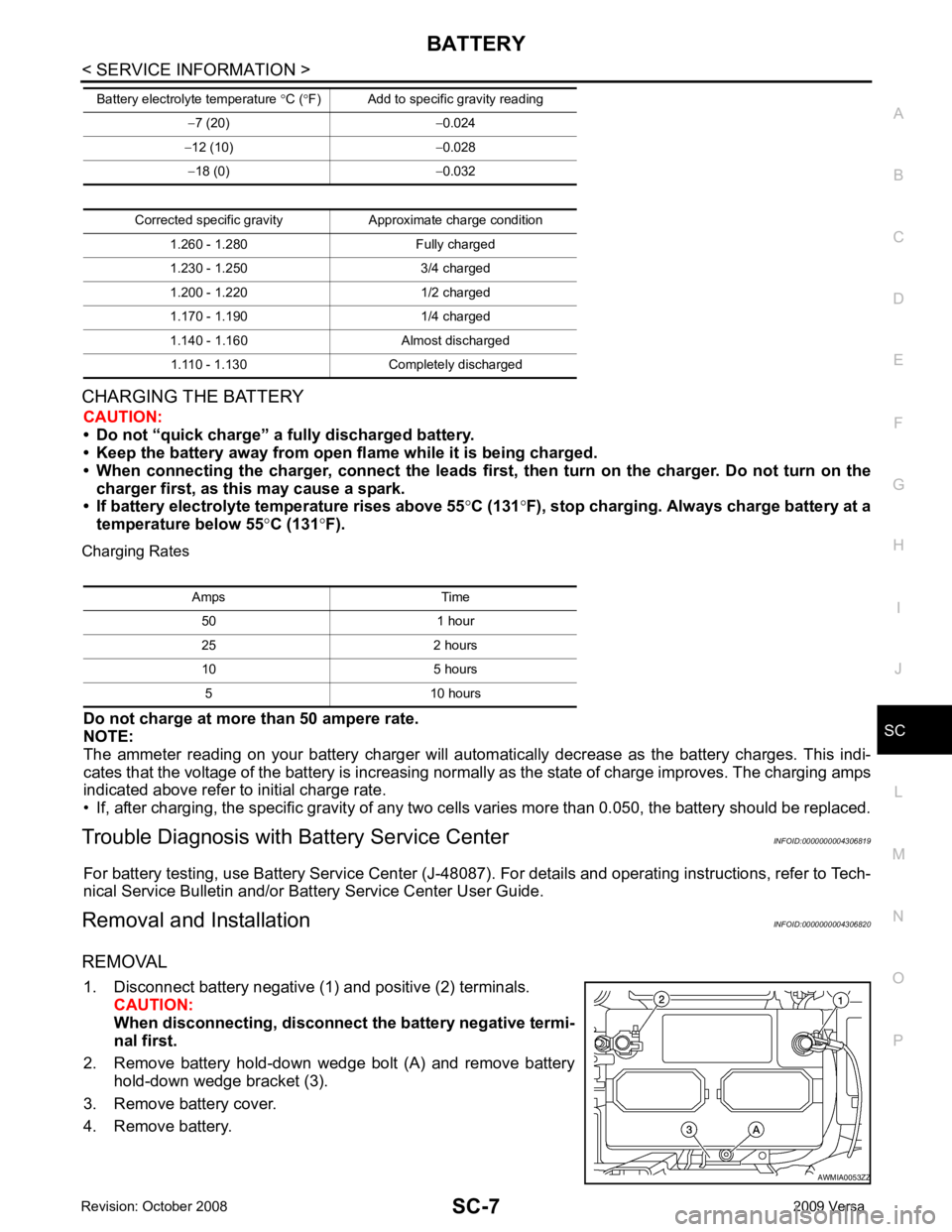
REMOVAL 1. Disconnect battery negative (1) and positive (2) terminals. CAUTION:
When disconnecting, disconnect the battery negative termi-
nal first.
2. Remove battery hold-down wedge bolt (A) and remove battery hold-down wedge bracket (3).
3. Remove battery cover.
4. Remove battery. −
7 (20) −0.024
− 12 (10) −0.028
− 18 (0) −0.032
Corrected specific gravity Approximate charge condition 1.260 - 1.280 Fully charged
1.230 - 1.250 3/4 charged
1.200 - 1.220 1/2 charged
1.170 - 1.190 1/4 charged
1.140 - 1.160 Almost discharged 1.110 - 1.130 Completely discharged
Battery electrolyte temperature
°C ( °F) Add to specific gravity reading Amps Time
50 1 hour
25 2 hours
10 5 hours 5 10 hours
Page 4157 of 4331
SC
N
O P
CHARGING SYSTEM
System Description INFOID:0000000004306825
The generator provides DC voltage to operate the vehicl e's electrical system and to keep the battery charged.
The voltage output is controlled by the IC regulator.
Power is supplied at all times to generator terminal 3 through
• 10A fuse (No. 29, located in the fuse and fusible link box).
Power is supplied through terminal 1 to charge the batte ry and operate the vehicle's electrical system. Output
voltage is monitored at terminal 3 by the IC regulator. The charging circuit is protected by the 120A fusible link
[letter a , located in the fusible link box (battery)].
Ground is supplied
• to generator terminal 5
• through body ground F5, and
• through the generator case to the cylinder block
With the ignition switch in the ON or START position, power is supplied
• through 10A fuse [No. 3, located in the fuse block (J/B)]
• to combination meter terminal 28 for the charge warning lamp.
The IC regulator controls ground to terminal 38 of the combination meter through terminal 2 of the generator.
When the ignition is turned on and power becomes availabl e at terminal 2, this "wakes up" the regulator. The
regulator monitors charge output and grounds terminal 2 or leaves it open depending on charge output. With
power and ground supplied, the charge warning lamp will il luminate. When the generator is providing sufficient
voltage, the ground is opened and the charge warning lamp will go off.
If the charge warning lamp illuminates with the engine running, a malfunction is indicated.
Page 4159 of 4331
SC
N
O P
WORK FLOW
DIAGNOSTIC PROCEDURE 1
Check Charge Warning Lamp Circuit OK >> GO TO 2.
NG >> Repair terminal 2 connection. Confirm repair by performing complete Starting/Charging system test. Refer to diagnostic station instruction manual. B
Page 4160 of 4331
![NISSAN LATIO 2009 Service Repair Manual OK >> GO TO "WORK FLOW" .
NG >> Check the following.
• 10A fuse [No. 3, located in fuse block (J/B)]
• CHARGE lamp
• Harness for open or short between combination meter and fuse
• Harness for NISSAN LATIO 2009 Service Repair Manual OK >> GO TO "WORK FLOW" .
NG >> Check the following.
• 10A fuse [No. 3, located in fuse block (J/B)]
• CHARGE lamp
• Harness for open or short between combination meter and fuse
• Harness for](/manual-img/5/57359/w960_57359-4159.png)
OK >> GO TO "WORK FLOW" .
NG >> Check the following.
• 10A fuse [No. 3, located in fuse block (J/B)]
• CHARGE lamp
• Harness for open or short between combination meter and fuse
• Harness for open or short between combination meter and generator
DIAGNOSTIC PROCEDURE 2
Check Battery Circuit OK >> GO TO 2.
NG >> Repair terminal 1 connection. Confirm repair by performing complete Starting/Charging system
test. Refer to diagnostic station instruction manual. OK >> GO TO 3.
NG >> Check the following. • 120A fusible link [letter a , located in fusible link box
(battery)]
• Harness for open or short between generator and fus- ible link OK >> Replace the generator. Refer to
SC-25, " Removal and
Installation " . Confirm repair by performing complete
Starting/Charging system test. Refer to diagnostic sta-
tion instruction manual.
NG >> Check harness between the battery and the generator for poor continuity.
DIAGNOSTIC PROCEDURE 3
Check Voltage Regulator Circuit CHARGE lamp should light up.
B