2009 NISSAN LATIO charging
[x] Cancel search: chargingPage 1141 of 4331
![NISSAN LATIO 2009 Service Repair Manual CVT FLUID
CVT-197
< SERVICE INFORMATION >
[RE0F08B] D
E
F
G H
I
J
K L
M A
B CVT
N
O P
FLUID CONDITION CHECK
Changing CVT Fluid INFOID:0000000004305571
1. Warm up CVT fluid by driving the vehicle for 1 NISSAN LATIO 2009 Service Repair Manual CVT FLUID
CVT-197
< SERVICE INFORMATION >
[RE0F08B] D
E
F
G H
I
J
K L
M A
B CVT
N
O P
FLUID CONDITION CHECK
Changing CVT Fluid INFOID:0000000004305571
1. Warm up CVT fluid by driving the vehicle for 1](/manual-img/5/57359/w960_57359-1140.png)
CVT FLUID
CVT-197
< SERVICE INFORMATION >
[RE0F08B] D
E
F
G H
I
J
K L
M A
B CVT
N
O P
FLUID CONDITION CHECK
Changing CVT Fluid INFOID:0000000004305571
1. Warm up CVT fluid by driving the vehicle for 10 minutes.
• : Vehicle front
• Radiator (2)
• CVT fluid cooler hose [inlet side (3)]
• Transaxle assembly (4)
2. Drain CVT fluid from CVT fluid cooler hose [outlet side (1)] and refill with new specified NISSAN CVT fluid in the CVT fluid
charging pipe with the engine running at idle speed.
CAUTION:
Only use the specifi ed NISSAN CVT fluid.
3. Refill until new CVT fluid comes out from CVT fluid cooler hose [outlet side (1)]. NOTE:
About 30 to 50% extra fluid will be required for this procedure.
4. Check fluid level and condition. Refer to CVT-196, " Checking CVT Fluid " .
CAUTION:
Delete CVT fluid deterioration date with CO NSULT-III after changing CVT fluid. Refer to CVT-230," CONSULT-III Function (TRANSMISSION) " .
CVT Fluid Cooler Cleaning INFOID:0000000004305572
Whenever a CVT is repaired, overhauled, or replaced, t he CVT fluid cooler mounted in the radiator must be
inspected and cleaned.
Metal debris and friction material, if present, can be trapped or become deposit in the CVT fluid cooler. This
debris can contaminate the newly serviced CVT or, in severe cases, can block or restrict the flow of CVT fluid.
In either case, malfunction of the newly serviced CVT may occur.
Debris, if present, may deposit as CVT fluid enters the cool er inlet. It will be necessary to back flush the cooler
through the cooler outlet in order to flush out any built up debris.
CVT FLUID COOLER CLEANING PROCEDURE 1. Identify the CVT inlet and outlet fluid cooler hoses.
2. Position an oil pan under the inlet and outlet cooler hoses. Fluid status Conceivable cause Required operation
Varnished (viscous
varnish state) Clutch, brake
scorched Replace the CVT fluid and check the
CVT main unit and the vehicle for
malfunctions (wire harness, cooler
pipes, etc.)
Milky white or cloudy Water in the fluid Replace the CVT fluid and check for places where water is getting in.
Large amount of
metal powder mixed
in fluid Unusual wear of
sliding parts within
CVT Replace the CVT fluid and check for
improper operation of the CVT. ATA0022D
Fluid capacity and grade: Refer to
MA-14, " Fluids
and Lubricants " .
SCIA6088E
Page 1298 of 4331
![NISSAN LATIO 2009 Service Repair Manual CVT-354< SERVICE INFORMATION >
[RE0F08B]
TRANSAXLE ASSEMBLY
TRANSAXLE ASSEMBLY
Removal and Installation INFOID:0000000004305824
COMPONENTS
REMOVAL
1. Remove the engine and transaxle as an assembly. Re NISSAN LATIO 2009 Service Repair Manual CVT-354< SERVICE INFORMATION >
[RE0F08B]
TRANSAXLE ASSEMBLY
TRANSAXLE ASSEMBLY
Removal and Installation INFOID:0000000004305824
COMPONENTS
REMOVAL
1. Remove the engine and transaxle as an assembly. Re](/manual-img/5/57359/w960_57359-1297.png)
CVT-354< SERVICE INFORMATION >
[RE0F08B]
TRANSAXLE ASSEMBLY
TRANSAXLE ASSEMBLY
Removal and Installation INFOID:0000000004305824
COMPONENTS
REMOVAL
1. Remove the engine and transaxle as an assembly. Refer to EM-195, " Removal and Installation " .
2. Disconnect the primary speed sensor (A) and the secondary speed sensor connector (B) and CVT unit connector (C). Refer
to CVT-191, " Removal and Installation Procedure for CVT Unit
Connector " .
3. Remove the harness from the transaxle. 1. CVT fluid level gauge 2. CVT fluid charging pipe 3. O-ring
4. Copper washer 5. Fluid cooler tube 6. Transaxle assembly
7. Engine mounting bracket (LH) 8. Air breather hose A. Refer to "INSTALLATION". WCIA0614E
AWDIA0661G B
Page 1299 of 4331
![NISSAN LATIO 2009 Service Repair Manual TRANSAXLE ASSEMBLY
CVT-355
< SERVICE INFORMATION >
[RE0F08B] D
E
F
G H
I
J
K L
M A
B CVT
N
O P
4. Remove the four drive plate to torque converter nuts.
NOTE:
Rotate the crankshaft clockwise as vi NISSAN LATIO 2009 Service Repair Manual TRANSAXLE ASSEMBLY
CVT-355
< SERVICE INFORMATION >
[RE0F08B] D
E
F
G H
I
J
K L
M A
B CVT
N
O P
4. Remove the four drive plate to torque converter nuts.
NOTE:
Rotate the crankshaft clockwise as vi](/manual-img/5/57359/w960_57359-1298.png)
TRANSAXLE ASSEMBLY
CVT-355
< SERVICE INFORMATION >
[RE0F08B] D
E
F
G H
I
J
K L
M A
B CVT
N
O P
4. Remove the four drive plate to torque converter nuts.
NOTE:
Rotate the crankshaft clockwise as viewed from front of engine
for access to drive plate to torque converter nuts.
5. Put matching marks on the drive plate and torque converter alignment stud. CAUTION:
For matching marks, use paint. Never dama ge the drive plate or torque converter.
6. Remove the transaxle to engine and engine to transaxle bolts.
7. Separate the transaxle from the engine.
8. If necessary, remove the following from the transaxle: • CVT fluid charging pipe
• Engine mounting bracket (LH)
• Fluid cooler tubes
• Air breather hose
• Any necessary brackets
INSTALLATION Installation is in the reverse order of removal.
CAUTION:
• When replacing an engine or transmission you mu st make sure any dowels are installed correctly
during re-assembly.
• Improper alignment caused by missing dowels m ay cause vibration, oil leaks or breakage of drive
train components.
• Do not reuse O-rings and copper washers.
• When turning crankshaft, turn it clockwise as viewed from the front of the engine.
• When tightening the nuts for the torque converter while securing the crankshaft pulley bolt, be sure
to confirm the tightening torque of the crankshaft pulley bolt. Refer to EM-160 .
• After converter is installed to drive plate, ro tate crankshaft several turns to check that transaxle
rotates freely without binding.
• When installing the torque converter to the transaxle measure dis- tance A. WCIA0616E
Distance A: 14.4 mm (0.57 in) or more
WCIA0617E
Page 2347 of 4331
![NISSAN LATIO 2009 Service Repair Manual FUEL PUMP
EC-991
< SERVICE INFOMATION >
[MR TYPE 1] C
D E
F
G H
I
J
K L
M A EC
NP
O
FUEL PUMP
Description INFOID:0000000004537529
SYSTEM DESCRIPTION
*: ECM determines the start signal status by the si NISSAN LATIO 2009 Service Repair Manual FUEL PUMP
EC-991
< SERVICE INFOMATION >
[MR TYPE 1] C
D E
F
G H
I
J
K L
M A EC
NP
O
FUEL PUMP
Description INFOID:0000000004537529
SYSTEM DESCRIPTION
*: ECM determines the start signal status by the si](/manual-img/5/57359/w960_57359-2346.png)
FUEL PUMP
EC-991
< SERVICE INFOMATION >
[MR TYPE 1] C
D E
F
G H
I
J
K L
M A EC
NP
O
FUEL PUMP
Description INFOID:0000000004537529
SYSTEM DESCRIPTION
*: ECM determines the start signal status by the signals of engine speed and battery voltage.
The ECM activates the fuel pump for several seconds after the ignition switch is turned ON to improve engine
startability. If the ECM receives a engine speed signal from the crankshaft position sensor (POS) and cam-
shaft position sensor (PHASE), it knows that the engi ne is rotating, and causes the pump to operate. If the
engine speed signal is not received when the ignition s witch is ON, the engine stalls. The ECM stops pump
operation and prevents battery discharging, thereby improving safety. The ECM does not directly drive the fuel
pump. It controls the ON/OFF fuel pump rela y, which in turn controls the fuel pump.
COMPONENT DESCRIPTION A turbine type design fuel pump is used in the fuel tank.
• Fuel level sensor unit and fuel pump (1)
• Fuel pressure regulator (2)
• Fuel level sensor (3)
• Fuel tank temperature sensor (4)
CONSULT-III Reference Val ue in Data Monitor Mode INFOID:0000000004537530
Specification data are reference values. Sensor Input Signal to ECM ECM Function Actuator
Crankshaft position sensor (POS)
Camshaft position sensor (PHASE) Engine speed*
Fuel pump control Fuel pump relay
Battery Battery voltage* Condition Fuel pump operation
Ignition switch is turned to ON Operates for 1 second
Engine running and cranking Operates
Engine: Stopped Stops in 1.5 seconds
Except as shown above Stops BBIA0704E
MONITOR ITEM CONDITION SPECIFICATION
FUEL PUMP RLY • For 1 second after turning ignition switch ON
• Engine running or cranking ON
• Except above conditions OFF
Page 2869 of 4331
![NISSAN LATIO 2009 Service Repair Manual FUEL PUMP
EC-1513
< SERVICE INFOMATION >
[MR TYPE 2] C
D E
F
G H
I
J
K L
M A EC
NP
O
FUEL PUMP
Description INFOID:0000000004500415
SYSTEM DESCRIPTION
*: ECM determines the start signal status by the s NISSAN LATIO 2009 Service Repair Manual FUEL PUMP
EC-1513
< SERVICE INFOMATION >
[MR TYPE 2] C
D E
F
G H
I
J
K L
M A EC
NP
O
FUEL PUMP
Description INFOID:0000000004500415
SYSTEM DESCRIPTION
*: ECM determines the start signal status by the s](/manual-img/5/57359/w960_57359-2868.png)
FUEL PUMP
EC-1513
< SERVICE INFOMATION >
[MR TYPE 2] C
D E
F
G H
I
J
K L
M A EC
NP
O
FUEL PUMP
Description INFOID:0000000004500415
SYSTEM DESCRIPTION
*: ECM determines the start signal status by the signals of engine speed and battery voltage.
The ECM activates the fuel pump for several seconds after the ignition switch is turned ON to improve engine
start ability. If the ECM receives a engine speed signal from the crankshaft position sensor (POS) and cam-
shaft position sensor (PHASE), it knows that the engi ne is rotating, and causes the pump to operate. If the
engine speed signal is not received when the ignition s witch is ON, the engine stalls. The ECM stops pump
operation and prevents battery discharging, thereby improving safety. The ECM does not directly drive the fuel
pump. It controls the ON/OFF fuel pump rela y, which in turn controls the fuel pump.
COMPONENT DESCRIPTION A turbine type design fuel pump is used in the fuel tank.
• Fuel level sensor unit and fuel pump (1)
• Fuel pressure regulator (2)
• Fuel level sensor (3)
• Fuel tank temperature sensor (4)
CONSULT-III Reference Val ue in Data Monitor Mode INFOID:0000000004500416
Specification data are reference values. Sensor Input Signal to ECM ECM Function Actuator
Crankshaft position sensor (POS)
Camshaft position sensor (PHASE) Engine speed*
Fuel pump control Fuel pump relay
Battery Battery voltage* Condition Fuel pump operation
Ignition switch is turned to ON Operates for 1 second
Engine running and cranking Operates
Engine: Stopped Stops in 1.5 seconds
Except as shown above Stops BBIA0704E
MONITOR ITEM CONDITION SPECIFICATION
FUEL PUMP RLY • For 1 second after turning ignition switch ON
• Engine running or cranking ON
• Except above conditions OFF
Page 3781 of 4331

MA-38< SERVICE INFORMATION >
CHASSIS AND BODY MAINTENANCE
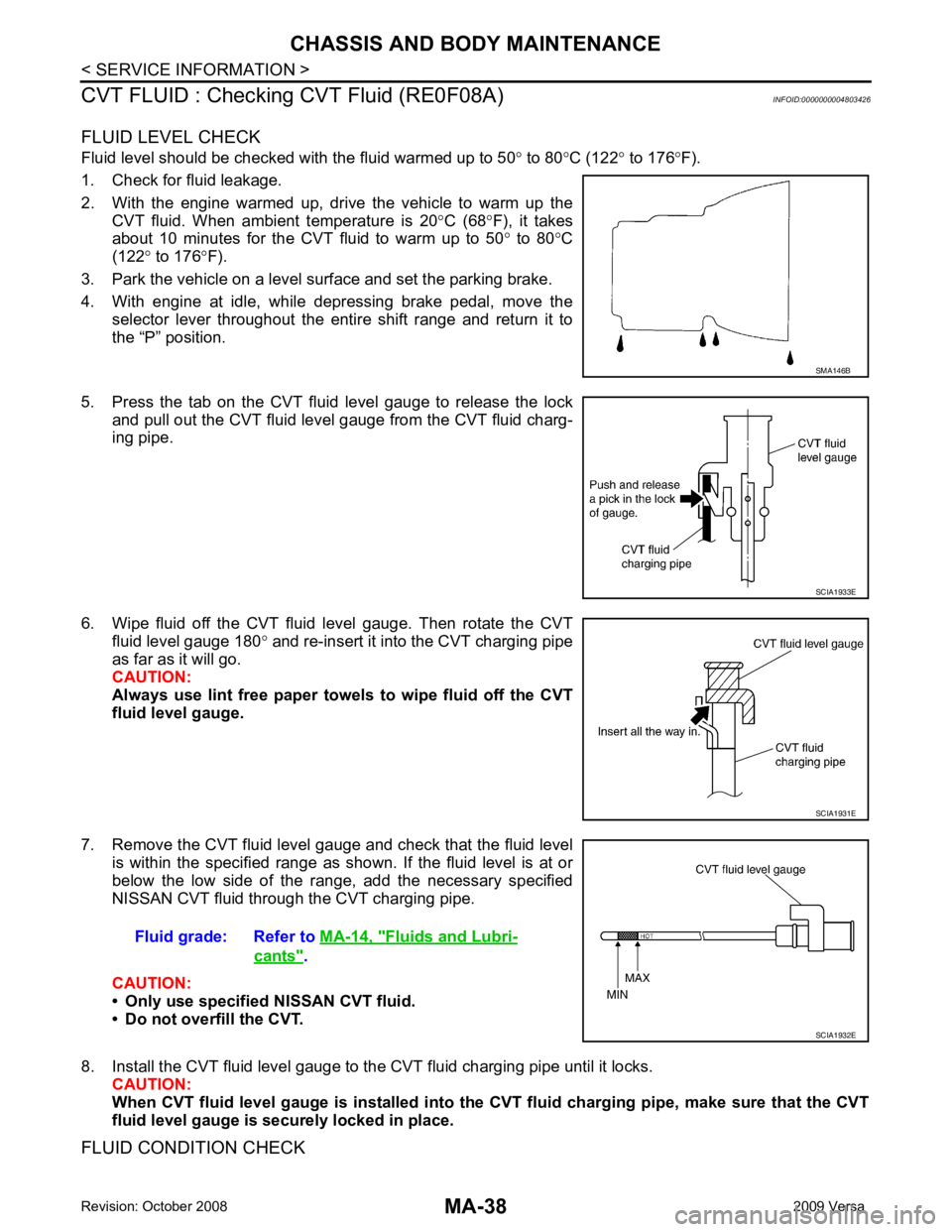
CVT FLUID : Checking CVT Fluid (RE0F08A) INFOID:0000000004803426
FLUID LEVEL CHECK
Fluid level should be checked with the fluid warmed up to 50 ° to 80 °C (122 ° to 176 °F).
1. Check for fluid leakage.
2. With the engine warmed up, drive the vehicle to warm up the CVT fluid. When ambient temperature is 20 °C (68 °F), it takes
about 10 minutes for the CVT fluid to warm up to 50 ° to 80 °C
(122 ° to 176 °F).
3. Park the vehicle on a level surface and set the parking brake.
4. With engine at idle, while depressing brake pedal, move the selector lever throughout the entire shift range and return it to
the “P” position.
5. Press the tab on the CVT fluid level gauge to release the lock and pull out the CVT fluid level gauge from the CVT fluid charg-
ing pipe.
6. Wipe fluid off the CVT fluid level gauge. Then rotate the CVT fluid level gauge 180 ° and re-insert it into the CVT charging pipe
as far as it will go.
CAUTION:
Always use lint free paper towels to wipe fluid off the CVT
fluid level gauge.
7. Remove the CVT fluid level gauge and check that the fluid level is within the specified range as shown. If the fluid level is at or
below the low side of the range, add the necessary specified
NISSAN CVT fluid through the CVT charging pipe.
CAUTION:
• Only use specified NISSAN CVT fluid.
• Do not overfill the CVT.
8. Install the CVT fluid level gauge to the CVT fluid charging pipe until it locks. CAUTION:
When CVT fluid level gauge is in stalled into the CVT fluid charging pipe, make sure that the CVT
fluid level gauge is securely locked in place.
FLUID CONDITION CHECK SMA146B
SCIA1933E
SCIA1931E
Fluid grade: Refer to
MA-14, " Fluids and Lubri-
cants " .
SCIA1932E
Page 3782 of 4331

CHASSIS AND BODY MAINTENANCE
MA-39
< SERVICE INFORMATION >
C
D E
F
G H
I
J
K
M A
B MA
N
O P
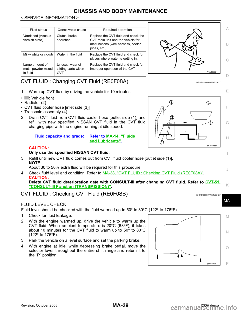
CVT FLUID : Changing CVT Fluid (RE0F08A)
INFOID:0000000004803427
1. Warm up CVT fluid by driving the vehicle for 10 minutes.
• : Vehicle front
• Radiator (2)
• CVT fluid cooler hose [inlet side (3)]
• Transaxle assembly (4)
2. Drain CVT fluid from CVT fluid cooler hose [outlet side (1)] and refill with new specified NISSAN CVT fluid in the CVT fluid
charging pipe with the engine running at idle speed.
CAUTION:
Only use the specifi ed NISSAN CVT fluid.
3. Refill until new CVT fluid comes out from CVT fluid cooler hose [outlet side (1)]. NOTE:
About 30 to 50% extra fluid will be required for this procedure.
4. Check fluid level and condition. Refer to MA-38, " CVT FLUID : Checking CVT Fluid (RE0F08A) " .
CAUTION:
Delete CVT fluid deterioration date with CONSULT-III after changing CVT fluid. Refer to CVT-51," CONSULT-III Function (TRANSMISSION) " .
CVT FLUID : Checking CVT Fluid (RE0F08B) INFOID:0000000004803428
FLUID LEVEL CHECK Fluid level should be checked with the fluid warmed up to 50 ° to 80 °C (122 ° to 176 °F).
1. Check for fluid leakage.
2. With the engine warmed up, drive the vehicle to warm up the CVT fluid. When ambient temperature is 20 °C (68 °F), it takes
about 10 minutes for the CVT fluid to warm up to 50 ° to 80 °C
(122 ° to 176 °F).
3. Park the vehicle on a level surface and set the parking brake.
4. With engine at idle, while depressing brake pedal, move the selector lever throughout the entire shift range and return it to
the “P” position. Fluid status Conceivable cause Required operation
Varnished (viscous
varnish state) Clutch, brake
scorched Replace the CVT fluid and check the
CVT main unit and the vehicle for
malfunctions (wire harness, cooler
pipes, etc.)
Milky white or cloudy Water in the fluid Replace the CVT fluid and check for places where water is getting in.
Large amount of
metal powder mixed
in fluid Unusual wear of
sliding parts within
CVT Replace the CVT fluid and check for
improper operation of the CVT. ATA0022D
Fluid capacity and grade: Refer to
MA-14, " Fluids
and Lubricants " .
SCIA6088E
SMA146B
Page 3783 of 4331

MA-40< SERVICE INFORMATION >
CHASSIS AND BODY MAINTENANCE
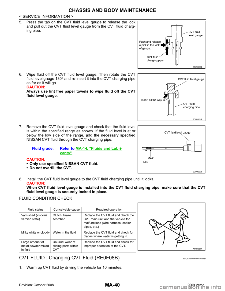
5. Press the tab on the CVT fluid level gauge to release the lock and pull out the CVT fluid level gauge from the CVT fluid charg-
ing pipe.
6. Wipe fluid off the CVT fluid level gauge. Then rotate the CVT fluid level gauge 180 ° and re-insert it into the CVT charging pipe
as far as it will go.
CAUTION:
Always use lint free paper towels to wipe fluid off the CVT
fluid level gauge.
7. Remove the CVT fluid level gauge and check that the fluid level is within the specified range as shown. If the fluid level is at or
below the low side of the range, add the necessary specified
NISSAN CVT fluid through the CVT charging pipe.
CAUTION:
• Only use specified NISSAN CVT fluid.
• Do not overfill the CVT.
8. Install the CVT fluid level gauge to the CVT fluid charging pipe until it locks. CAUTION:
When CVT fluid level gauge is in stalled into the CVT fluid charging pipe, make sure that the CVT
fluid level gauge is securely locked in place.
FLUID CONDITION CHECK
CVT FLUID : Changing CVT Fluid (RE0F08B) INFOID:0000000004803429
1. Warm up CVT fluid by driving the vehicle for 10 minutes. SCIA1933E
SCIA1931E
Fluid grade: Refer to
MA-14, " Fluids and Lubri-
cants " .
SCIA1932E
Fluid status Conceivable cause Required operation
Varnished (viscous
varnish state) Clutch, brake
scorched Replace the CVT fluid and check the
CVT main unit and the vehicle for
malfunctions (wire harness, cooler
pipes, etc.)
Milky white or cloudy Water in the fluid Replace the CVT fluid and check for places where water is getting in.
Large amount of
metal powder mixed
in fluid Unusual wear of
sliding parts within
CVT Replace the CVT fluid and check for
improper operation of the CVT. ATA0022D