2009 NISSAN LATIO display
[x] Cancel search: displayPage 2255 of 4331
EC
NP
O
DTC P1421 COLD START CONTROL
Description INFOID:0000000004537411
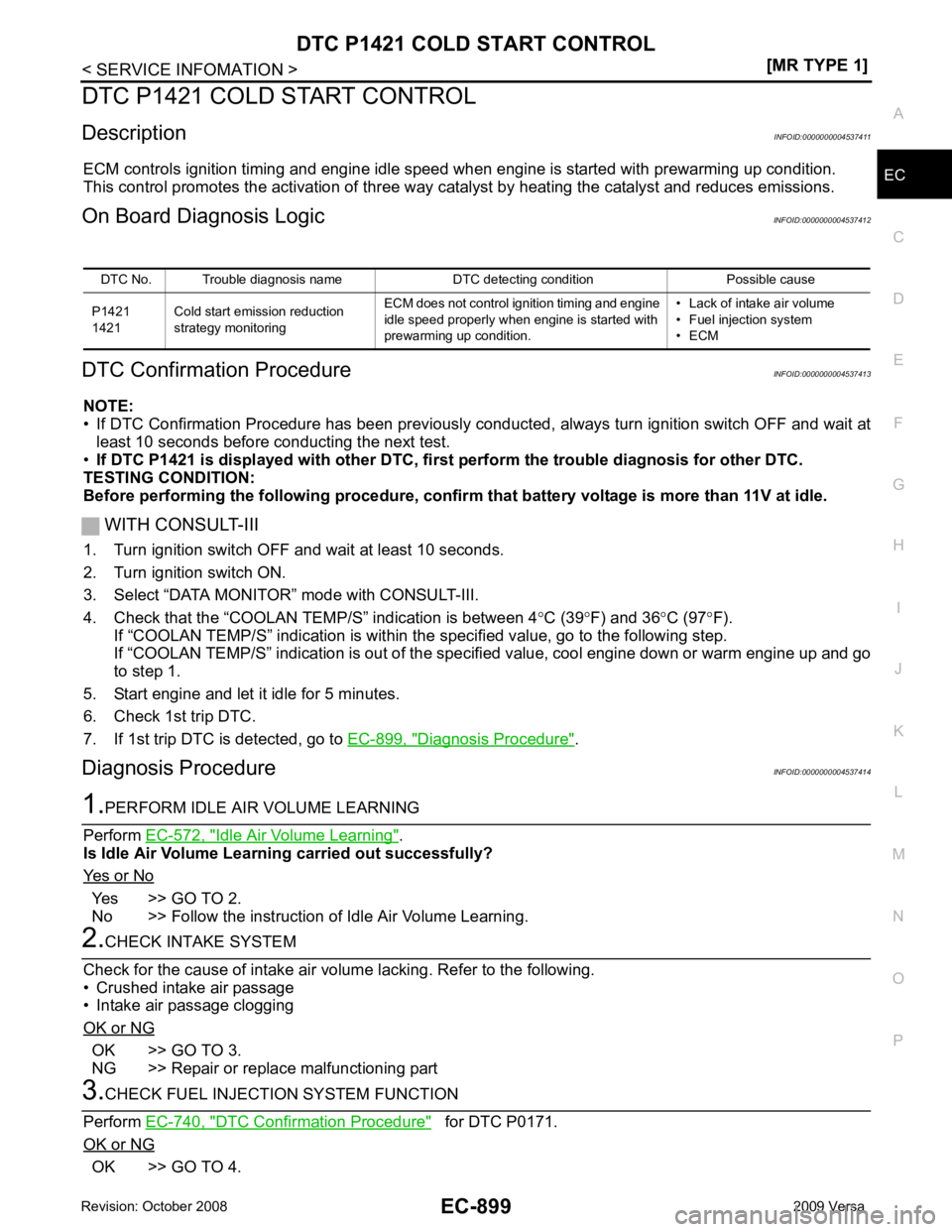
ECM controls ignition timing and engine idle speed when engine is started with prewarming up condition.
This control promotes the activation of three way ca talyst by heating the catalyst and reduces emissions.
On Board Diagnosis Logic INFOID:0000000004537412
DTC Confirmation Procedure INFOID:0000000004537413
NOTE:
• If DTC Confirmation Procedure has been previously conduc ted, always turn ignition switch OFF and wait at
least 10 seconds before conducting the next test.
• If DTC P1421 is displayed with other DTC, firs t perform the trouble diagnosis for other DTC.
TESTING CONDITION:
Before performing the following procedure, confirm that battery voltage is more than 11V at idle.
WITH CONSULT-III
1. Turn ignition switch OFF and wait at least 10 seconds.
2. Turn ignition switch ON.
3. Select “DATA MONITOR” mode with CONSULT-III.
4. Check that the “COOLAN TE MP/S” indication is between 4°C (39 °F) and 36 °C (97 °F).
If “COOLAN TEMP/S” indication is within the specified value, go to the following step.
If “COOLAN TEMP/S” indication is out of the s pecified value, cool engine down or warm engine up and go
to step 1.
5. Start engine and let it idle for 5 minutes.
6. Check 1st trip DTC.
7. If 1st trip DTC is detected, go to EC-899, " Diagnosis Procedure " .
Diagnosis Procedure INFOID:0000000004537414Idle Air Volume Learning " .
Is Idle Air Volume Learning carried out successfully?
Yes or No Yes >> GO TO 2.
No >> Follow the instruction of Idle Air Volume Learning. OK >> GO TO 3.
NG >> Repair or replace malfunctioning part DTC Confirmation Procedure " for DTC P0171.
OK or NG OK >> GO TO 4.DTC No. Trouble diagnosis name DTC detecting condition Possible cause
P1421
1421 Cold start emission reduction
strategy monitoring ECM does not control ignition timing and engine
idle speed properly when engine is started with
prewarming up condition. • Lack of intake air volume
• Fuel injection system
• ECM
Page 2256 of 4331
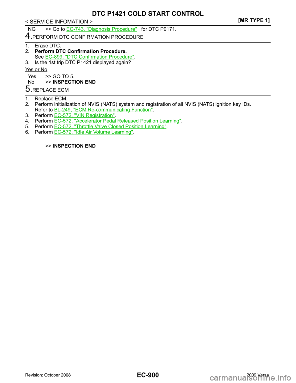
Diagnosis Procedure " for DTC P0171.
DTC Confirmation Procedure " .
3. Is the 1st trip DTC P1421 displayed again?
Yes or No Yes >> GO TO 5.
No >> INSPECTION END ECM Re-communicating Function " .
3. Perform EC-572, " VIN Registration " .
4. Perform EC-572, " Accelerator Pedal Released Position Learning " .
5. Perform EC-572, " Throttle Valve Closed Position Learning " .
6. Perform EC-572, " Idle Air Volume Learning " .
>> INSPECTION END
Page 2257 of 4331
EC
NP
O
DTC P1564 ASCD STEERING SWITCH
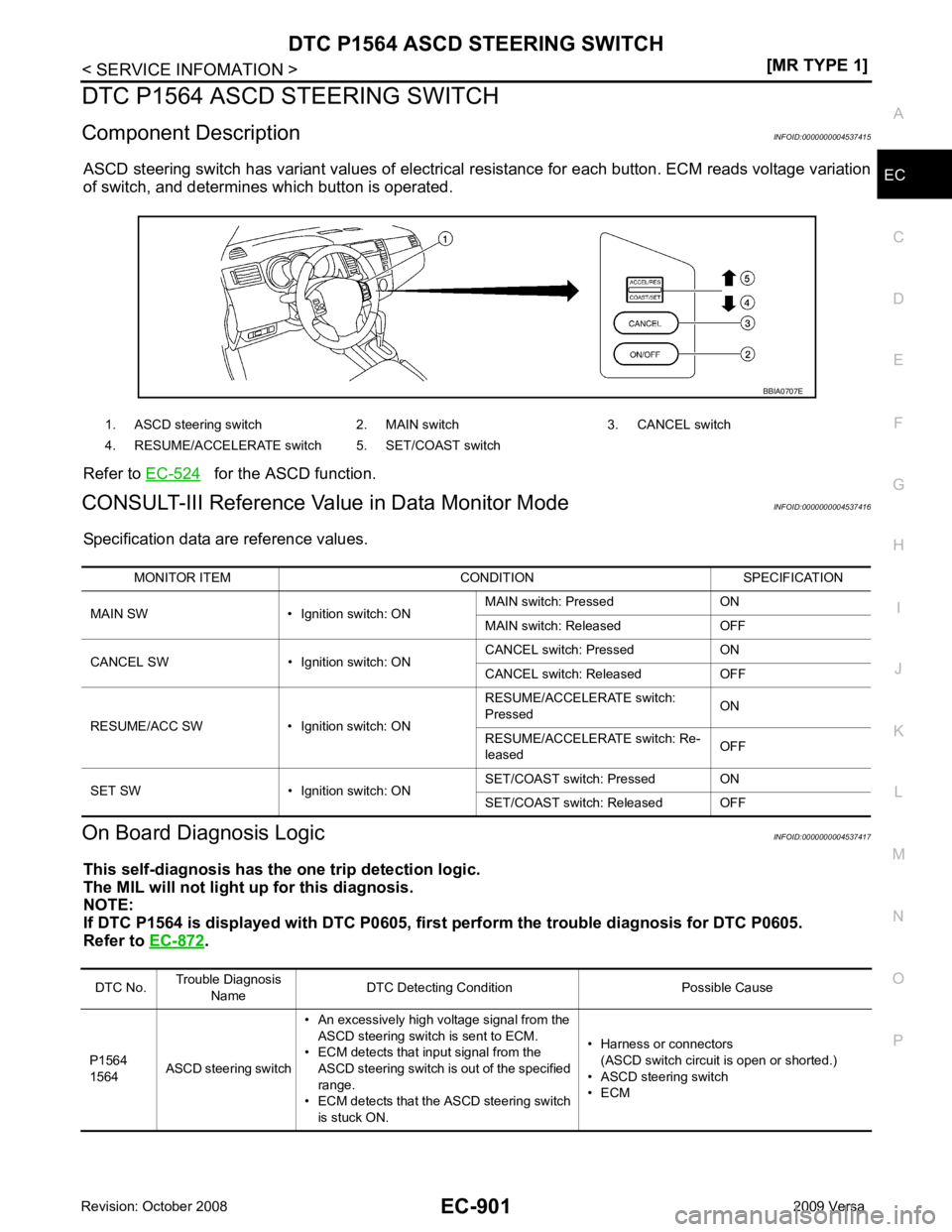
Component Description INFOID:0000000004537415
ASCD steering switch has variant values of electrical resistance for each button. ECM reads voltage variation
of switch, and determines which button is operated.
Refer to EC-524 for the ASCD function.
CONSULT-III Reference Val ue in Data Monitor Mode INFOID:0000000004537416
Specification data are reference values.
On Board Diagnosis Logic INFOID:0000000004537417
This self-diagnosis has the on e trip detection logic.
The MIL will not light up for this diagnosis.
NOTE:
If DTC P1564 is displayed with DTC P0605, first perform the trouble diagnosis for DTC P0605.
Refer to EC-872 .
1. ASCD steering switch 2. MAIN switch 3. CANCEL switch
4. RESUME/ACCELERATE switch 5. SET/COAST switch DTC No.
Trouble Diagnosis
Name DTC Detecting Condit
ion Possible Cause
P1564
1564 ASCD steering switch • An excessively high voltage signal from the
ASCD steering switch is sent to ECM.
• ECM detects that input signal from the
ASCD steering switch is out of the specified
range.
• ECM detects that the ASCD steering switch
is stuck ON. • Harness or connectors
(ASCD switch circuit is open or shorted.)
• ASCD steering switch
• ECM
Page 2263 of 4331
EC
NP
O
DTC P1572 ASCD BRAKE SWITCH
Component Description INFOID:0000000004537422
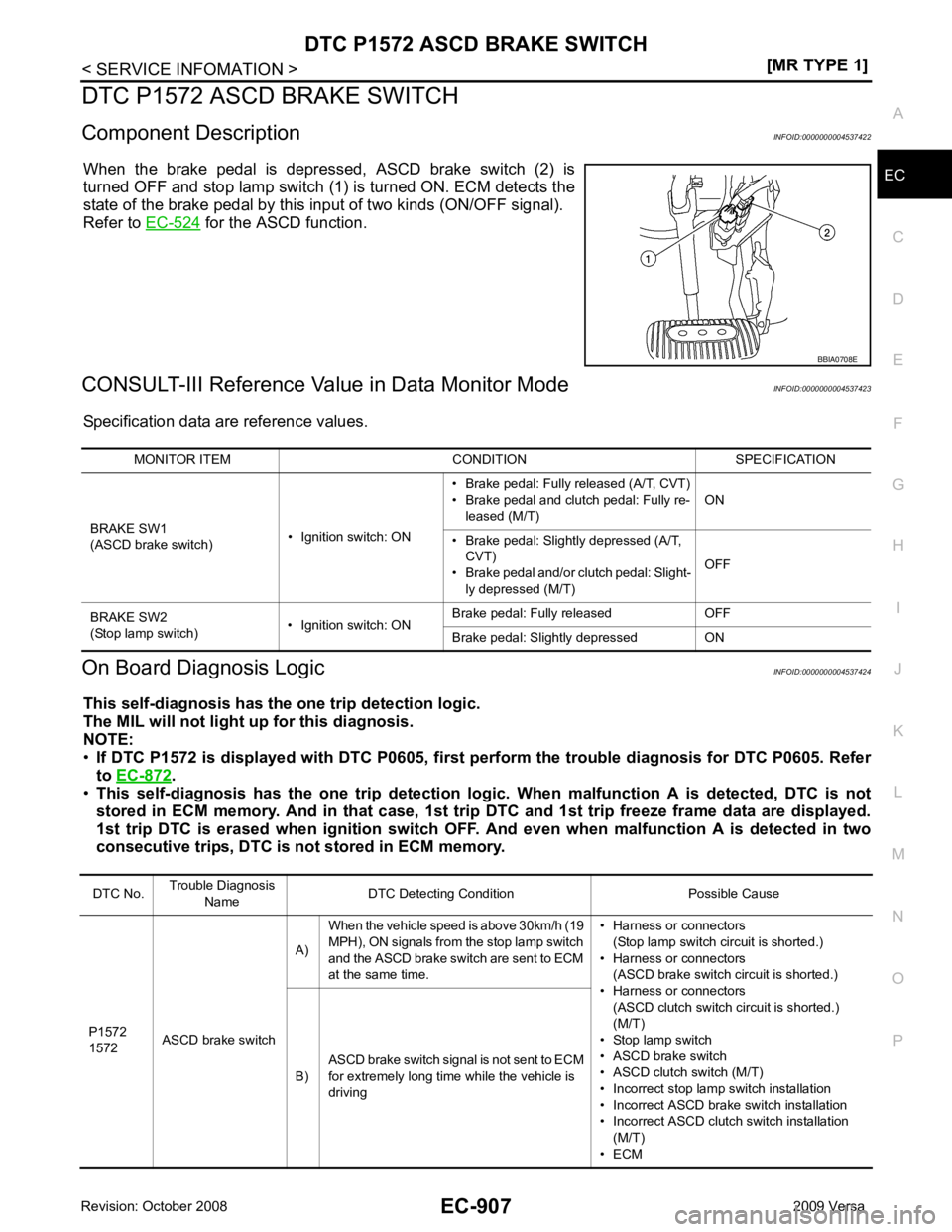
When the brake pedal is depressed, ASCD brake switch (2) is
turned OFF and stop lamp switch (1) is turned ON. ECM detects the
state of the brake pedal by this input of two kinds (ON/OFF signal).
Refer to EC-524 for the ASCD function.
CONSULT-III Reference Val ue in Data Monitor Mode INFOID:0000000004537423
Specification data are reference values.
On Board Diagnosis Logic INFOID:0000000004537424
This self-diagnosis has the on e trip detection logic.
The MIL will not light up for this diagnosis.
NOTE:
• If DTC P1572 is displayed with DT C P0605, first perform the trouble diagnosis for DTC P0605. Refer
to EC-872 .
• This self-diagnosis has the one trip detection logic. When malfunction A is detected, DTC is not
stored in ECM memory. And in that case, 1st trip DTC and 1st trip freeze frame data are displayed.
1st trip DTC is erased when igniti on switch OFF. And even when ma lfunction A is detected in two
consecutive trips, DTC is not stored in ECM memory. DTC No.
Trouble Diagnosis
Name DTC Detecting Condition Possible Cause
P1572
1572 ASCD brake switch A)
When the vehicle speed is above 30km/h (19
MPH), ON signals from the stop lamp switch
and the ASCD brake switch are sent to ECM
at the same time. • Harness or connectors
(Stop lamp switch circuit is shorted.)
• Harness or connectors (ASCD brake switch circuit is shorted.)
• Harness or connectors
(ASCD clutch switch circuit is shorted.)
(M/T)
• Stop lamp switch
• ASCD brake switch
• ASCD clutch switch (M/T)
• Incorrect stop lamp switch installation
• Incorrect ASCD brake switch installation
• Incorrect ASCD clutch switch installation (M/T)
• ECM
B)
ASCD brake switch signal is not sent to ECM
for extremely long time while the vehicle is
driving
Page 2272 of 4331
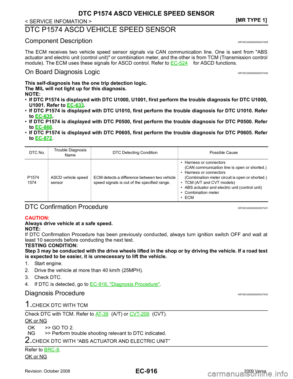
for ASCD functions.
On Board Diagn osis Logic INFOID:0000000004537430
This self-diagnosis has the one trip detection logic.
The MIL will not light up for this diagnosis.
NOTE:
• If DTC P1574 is displayed with DTC U1000, U1001, first perform the trouble diagnosis for DTC U1000,
U1001. Refer to EC-633 .
• If DTC P1574 is displayed with DTC U1010, first pe rform the trouble diagnosis for DTC U1010. Refer
to EC-635 .
• If DTC P1574 is displayed with DTC P0500, first pe rform the trouble diagnosis for DTC P0500. Refer
to EC-866 Diagnosis Procedure " .
Diagnosis Procedure INFOID:0000000004537432 (A/T) or
CVT-209 (CVT).
OK or NG OK >> GO TO 2.
NG >> Perform trouble shooting relevant to DTC indicated. .
OK or NG
Page 2274 of 4331
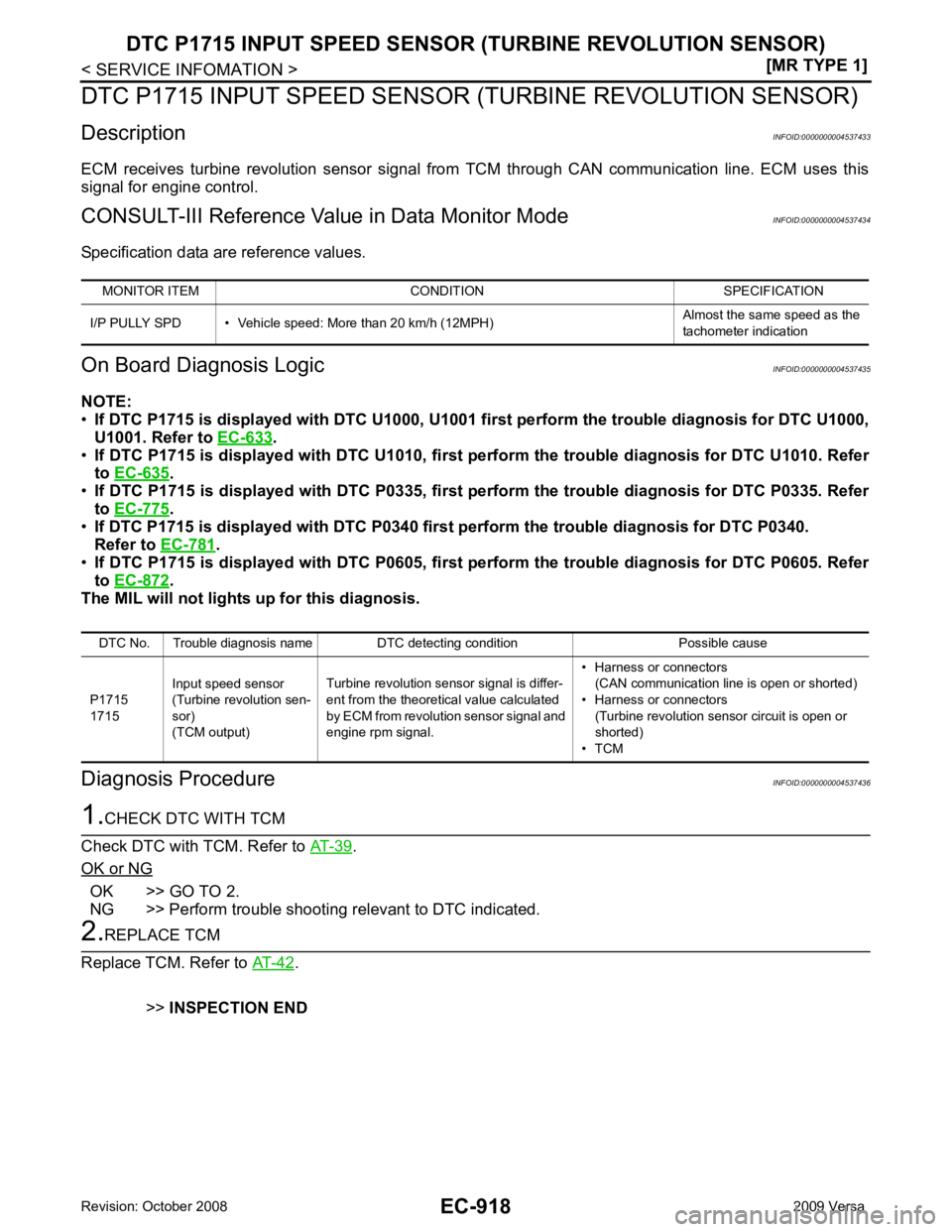
.
• If DTC P1715 is displayed with DTC U1010, first pe rform the trouble diagnosis for DTC U1010. Refer
to EC-635 .
• If DTC P1715 is displayed with DTC P0335, first pe rform the trouble diagnosis for DTC P0335. Refer
to EC-775 .
• If DTC P1715 is displayed with DTC P0340 first perform the trouble diagnosis for DTC P0340.
Refer to EC-781 .
• If DTC P1715 is displayed with DTC P0605, first pe rform the trouble diagnosis for DTC P0605. Refer
to EC-872 .
The MIL will not lights up for this diagnosis.
Diagnosis Procedure INFOID:0000000004537436.
OK or NG OK >> GO TO 2.
NG >> Perform trouble shooting relevant to DTC indicated. .
>> INSPECTION END
MONITOR ITEM CONDITION SPECIFICATION
I/P PULLY SPD • Vehicle speed: More than 20 km/h (12MPH) Almost the same speed as the
tachometer indication DTC No. Trouble diagnosis name DTC detecting condition Possible cause
P1715
1715 Input speed sensor
(Turbine revolution sen-
sor)
(TCM output) Turbine revolution sensor signal is differ-
ent from the theoretical value calculated
by ECM from revolution sensor signal and
engine rpm signal. • Harness or connectors
(CAN communication line is open or shorted)
• Harness or connectors
(Turbine revolution sensor circuit is open or
shorted)
• TCM
Page 2275 of 4331
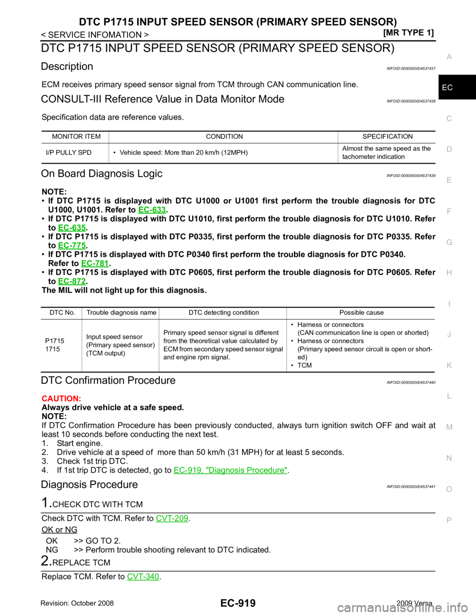
EC
NP
O
DTC P1715 INPUT SPEED SENS
OR (PRIMARY SPEED SENSOR)
Description INFOID:0000000004537437
ECM receives primary speed sensor signal from TCM through CAN communication line.
CONSULT-III Reference Val ue in Data Monitor Mode INFOID:0000000004537438
Specification data are reference values.
On Board Diagnosis Logic INFOID:0000000004537439
NOTE:
• If DTC P1715 is displayed with DTC U1000 or U 1001 first perform the trouble diagnosis for DTC
U1000, U1001. Refer to EC-633 .
• If DTC P1715 is displayed with DTC U1010, firs t perform the trouble diagnosis for DTC U1010. Refer
to EC-635 .
• If DTC P1715 is displayed with DT C P0335, first perform the trouble diagnosis for DTC P0335. Refer
to EC-775 .
• If DTC P1715 is displayed with DTC P0340 firs t perform the trouble diagnosis for DTC P0340.
Refer to EC-781 .
• If DTC P1715 is displayed with DT C P0605, first perform the trouble diagnosis for DTC P0605. Refer
to EC-872 .
The MIL will not light up for this diagnosis.
DTC Confirmation Procedure INFOID:0000000004537440
CAUTION:
Always drive vehicle at a safe speed.
NOTE:
If DTC Confirmation Procedure has been previously conduc ted, always turn ignition switch OFF and wait at
least 10 seconds before conducting the next test.
1. Start engine.
2. Drive vehicle at a speed of more than 50 km/h (31 MPH) for at least 5 seconds.
3. Check 1st trip DTC.
4. If 1st trip DTC is detected, go to EC-919, " Diagnosis Procedure " .
Diagnosis Procedure INFOID:0000000004537441.
OK or NG OK >> GO TO 2.
NG >> Perform trouble shooting relevant to DTC indicated. .
MONITOR ITEM CONDITION SPECIFICATION
I/P PULLY SPD • Vehicle speed: More than 20 km/h (12MPH) Almost the same speed as the
tachometer indication DTC No. Trouble diagnosis name DTC detecting condition Possible cause
P1715
1715 Input speed sensor
(Primary speed sensor)
(TCM output) Primary speed sensor signal is different
from the theoretical value calculated by
ECM from secondary speed sensor signal
and engine rpm signal. • Harness or connectors
(CAN communication line is open or shorted)
• Harness or connectors (Primary speed sensor circuit is open or short-
ed)
• TCM
Page 2285 of 4331
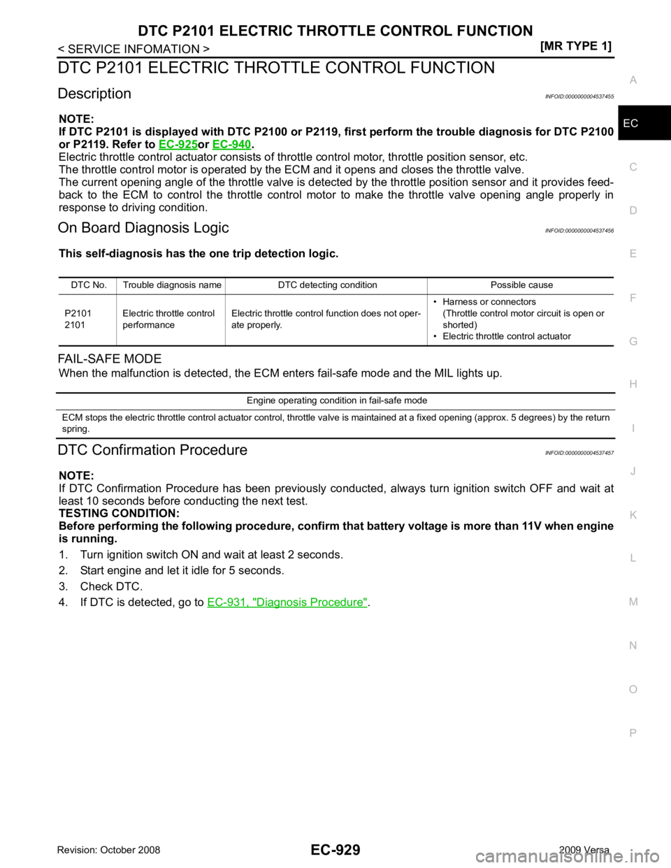
EC
NP
O
DTC P2101 ELECTRIC THRO
TTLE CONTROL FUNCTION
Description INFOID:0000000004537455
NOTE:
If DTC P2101 is displayed with DTC P2100 or P2119, first perform the trouble diagnosis for DTC P2100
or P2119. Refer to EC-925 or
EC-940 .
Electric throttle control actuator consists of throttle control motor, throttle position sensor, etc.
The throttle control motor is operated by the ECM and it opens and closes the throttle valve.
The current opening angle of the throttle valve is detected by the throttle position sensor and it provides feed-
back to the ECM to control the throttle control motor to make the throttle valve opening angle properly in
response to driving condition.
On Board Diagnosis Logic INFOID:0000000004537456
This self-diagnosis has the on e trip detection logic.
FAIL-SAFE MODE When the malfunction is detec ted, the ECM enters fail-safe mode and the MIL lights up.
DTC Confirmation Procedure INFOID:0000000004537457
NOTE:
If DTC Confirmation Procedure has been previously conduc ted, always turn ignition switch OFF and wait at
least 10 seconds before conducting the next test.
TESTING CONDITION:
Before performing the follo wing procedure, confirm that battery vo ltage is more than 11V when engine
is running.
1. Turn ignition switch ON and wait at least 2 seconds.
2. Start engine and let it idle for 5 seconds.
3. Check DTC.
4. If DTC is detected, go to EC-931, " Diagnosis Procedure " .
DTC No. Trouble diagnosis name DTC detecting condition Possible cause
P2101
2101 Electric throttle control
performance Electric throttle control function does not oper-
ate properly. • Harness or connectors
(Throttle control motor circuit is open or
shorted)
• Electric throttle control actuator Engine operating condition in fail-safe mode
ECM stops the electric throttle control actuator control, throttle valve is maintained at a fixed opening (approx. 5 degrees) b y the return
spring.