2009 NISSAN LATIO display
[x] Cancel search: displayPage 1967 of 4331
![NISSAN LATIO 2009 Service Repair Manual EC
NP
O
NOTE:
Any monitored item that does not match the vehicle being diagnosed is deleted from the display automatically.
ACTIVE TEST MODE
Test Item AT OD CANCEL
[ON/OFF] • Indicates [ON/OFF] cond NISSAN LATIO 2009 Service Repair Manual EC
NP
O
NOTE:
Any monitored item that does not match the vehicle being diagnosed is deleted from the display automatically.
ACTIVE TEST MODE
Test Item AT OD CANCEL
[ON/OFF] • Indicates [ON/OFF] cond](/manual-img/5/57359/w960_57359-1966.png)
EC
NP
O
NOTE:
Any monitored item that does not match the vehicle being diagnosed is deleted from the display automatically.
ACTIVE TEST MODE
Test Item AT OD CANCEL
[ON/OFF] • Indicates [ON/OFF] condition of A/T O/D cancel signal sent
from the TCM. • For M/T models always “OFF” is displayed
CRUISE LAMP
[ON/OFF] • Indicates [ON/OFF]
condition of CRUISE lamp determined
by the ECM according to the input signals.
SET LAMP
[ON/OFF] • Indicates [ON/OFF] condition of SET lamp determined by the
ECM according to the input signals.
A/F ADJ-B1 • Indicates the correction factor stored in ECM. The factor is
calculated from the difference between the target air/fuel ratio
stored in ECM and the air/fuel ratio calculated from air fuel ra-
tio (A/F) sensor 1 signal.
Monitored item [Unit] Description Remarks TEST ITEM CONDITION JUDGEMENT CHECK ITEM (REMEDY)
FUEL INJEC-
TION • Engine: Return to the original
trouble condition
• Change the amount of fuel injec- tion using CONSULT-III. If trouble symptom disappears, see
CHECK ITEM. • Harness and connectors
• Fuel injector
• Air fuel ratio (A/F) sensor 1
IGNITION TIM-
ING • Engine: Return to the original
trouble condition
• Timing light: Set
• Retard the ignition timing using
CONSULT-III. If trouble symptom disappears, see
CHECK ITEM. • Perform Idle Air Volume Learning.
POWER BAL-
ANCE • Engine: After warming up, idle the
engine.
• A/C switch OFF
• Shift lever: P or N (A/T, CVT), Neutral (M/T)
• Cut off each fuel injector signal
one at a time using CONSULT-III. Engine runs rough or dies.
• Harness and connectors
• Compression
• Fuel injector
• Power transistor
• Spark plug
• Ignition coil
COOLING FAN* • Ignition switch: ON
• Turn the cooling fan “LOW”, “HI” and “OFF” with CONSULT-III. Cooling fan moves and stops. • Harness and connectors
• Cooling fan relay
• Cooling fan motor
ENG COOLANT
TEMP • Engine: Return to the original
trouble condition
• Change the engine coolant tem- perature using CONSULT-III. If trouble symptom disappears, see
CHECK ITEM. • Harness and connectors
• Engine coolant temperature sen-
sor
• Fuel injector
FUEL PUMP RE-
LAY • Ignition switch: ON
(Engine stopped)
• Turn the fuel pump relay ON and OFF using CONSULT-III and lis-
ten to operating sound. Fuel pump relay makes the operat-
ing sound. • Harness and connectors
• Fuel pump relay
PURG VOL
CONT/V • Engine: After warming up, run en-
gine at 1,500 rpm.
• Change the EVAP canister purge volume control solenoid valve
opening percent using CON-
SULT-III. Engine speed changes according to
the opening percent. • Harness and connectors
• EVAP canister purge volume con- trol solenoid valve
FUEL/T TEMP
SEN • Change the fuel tank temperature using CONSULT-III.
Page 1991 of 4331

EC
NP
O
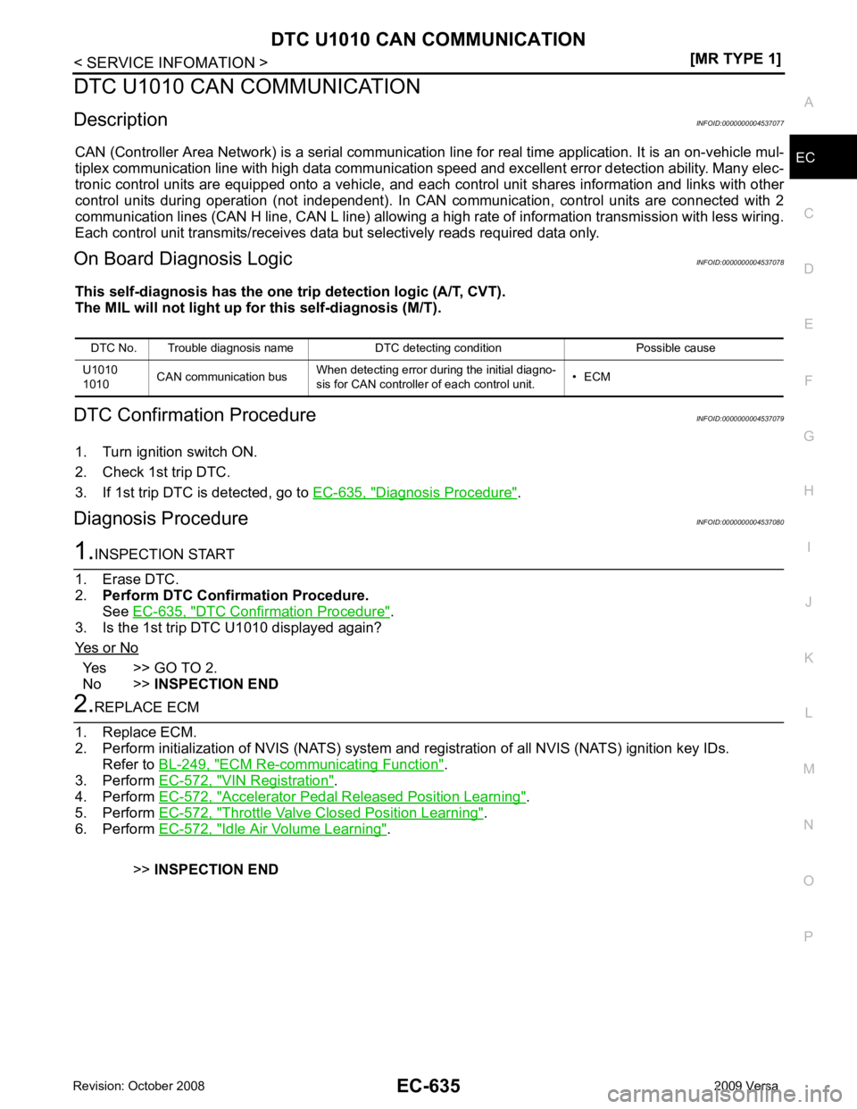
DTC U1010 CAN COMMUNICATION
Description INFOID:0000000004537077
CAN (Controller Area Network) is a serial communication li ne for real time application. It is an on-vehicle mul-
tiplex communication line with high data communication speed and excellent error detection ability. Many elec-
tronic control units are equipped onto a vehicle, and each control unit shares information and links with other
control units during operation (not independent). In CAN communication, control units are connected with 2
communication lines (CAN H line, CAN L line) allowing a high rate of information transmission with less wiring.
Each control unit transmits/receives data but selectively reads required data only.
On Board Diagnosis Logic INFOID:0000000004537078
This self-diagnosis has the one trip detection logic (A/T, CVT).
The MIL will not light up for this self-diagnosis (M/T).
DTC Confirmation Procedure INFOID:0000000004537079
1. Turn ignition switch ON.
2. Check 1st trip DTC.
3. If 1st trip DTC is detected, go to EC-635, " Diagnosis Procedure " .
Diagnosis Procedure INFOID:0000000004537080DTC Confirmation Procedure " .
3. Is the 1st trip DTC U1010 displayed again?
Yes or No Yes >> GO TO 2.
No >> INSPECTION END ECM Re-communicating Function " .
3. Perform EC-572, " VIN Registration " .
4. Perform EC-572, " Accelerator Pedal Released Position Learning " .
5. Perform EC-572, " Throttle Valve Closed Position Learning " .
6. Perform EC-572, " Idle Air Volume Learning " .
>> INSPECTION END
DTC No. Trouble diagnosis name DTC detecting condition Possible cause
U1010
1010 CAN communication bus
When detecting error during the initial diagno-
sis for CAN controller of each control unit. • ECM
Page 1993 of 4331

EC
NP
O
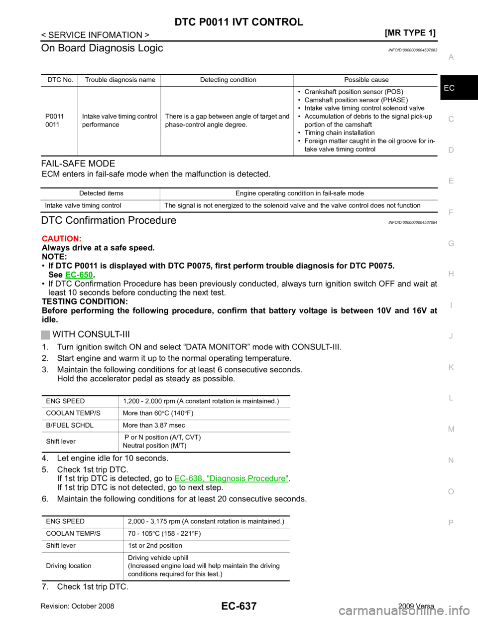
On Board Diagnosis Logic
INFOID:0000000004537083
FAIL-SAFE MODE ECM enters in fail-safe mode w hen the malfunction is detected.
DTC Confirmation Procedure INFOID:0000000004537084
CAUTION:
Always drive at a safe speed.
NOTE:
• If DTC P0011 is displayed with DTC P0075, first perform trouble diagnosis for DTC P0075.
See EC-650 .
• If DTC Confirmation Procedure has been previously conduc ted, always turn ignition switch OFF and wait at
least 10 seconds before conducting the next test.
TESTING CONDITION:
Before performing the following procedure, confi rm that battery voltage is between 10V and 16V at
idle.
WITH CONSULT-III
1. Turn ignition switch ON and select “DATA MONITOR” mode with CONSULT-III.
2. Start engine and warm it up to the normal operating temperature.
3. Maintain the following conditions for at least 6 consecutive seconds. Hold the accelerator pedal as steady as possible.
4. Let engine idle for 10 seconds.
5. Check 1st trip DTC. If 1st trip DTC is detected, go to EC-638, " Diagnosis Procedure " .
If 1st trip DTC is not detected, go to next step.
6. Maintain the following conditions for at least 20 consecutive seconds.
7. Check 1st trip DTC. DTC No. Trouble diagnosis name Detecting condition Possible cause
P0011
0011 Intake valve timing control
performance There is a gap between angle of target and
phase-control angle degree. • Crankshaft position sensor (POS)
• Camshaft position sensor (PHASE)
• Intake valve timing control solenoid valve
• Accumulation of debris to the signal pick-up portion of the camshaft
• Timing chain installation
• Foreign matter caught in the oil groove for in- take valve timing control Detected items Engine operating condition in fail-safe mode
Intake valve timing control The signal is not energized to the solenoid valve and the valve control does not function ENG SPEED 1,200 - 2,000 rpm (A constant rotation is maintained.)
COOLAN TEMP/S More than 60 °C (140 °F)
B/FUEL SCHDL More than 3.87 msec
Shift lever P or N position (A/T, CVT)
Neutral position (M/T)
ENG SPEED 2,000 - 3,175 rpm (A constant rotation is maintained.)
COOLAN TEMP/S 70 - 105 °C (158 - 221 °F)
Shift lever 1st or 2nd position
Driving location Driving vehicle uphill
(Increased engine load will help maintain the driving
conditions required for this test.)
Page 2031 of 4331

EC
NP
O
DTC Confirmation Procedure
INFOID:0000000004537138
NOTE:
If DTC Confirmation Procedure has been previously conduc ted, always turn ignition switch OFF and wait at
least 10 seconds before conducting the next test.
WITH CONSULT-III
1. Turn ignition switch ON and wait at least 5 seconds.
2. Check DTC.
3. If DTC is detected, go to EC-676, " Diagnosis Procedure " .
Detected items Engine operating condition in fail-safe mode
Engine coolant temper- ature sensor circuit Engine coolant temperature will be determined by ECM based on the following condition.
CONSULT-III displays the engine coolant temperature decided by ECM.
Condition Engine coolant temperature decided
(CONSULT-III display)
Just as ignition switch is turned ON or START 40 °C (104 °F)
Approx. 4 minutes or more after engine starting. 80 °C (176 °F)
Except as shown above 40 - 80
°C (104 - 176 °F)
(Depends on the time)
When the fail-safe system for engine coolant temperature sensor is activated, the cooling fan operates while
engine is running.
Page 2035 of 4331
![NISSAN LATIO 2009 Service Repair Manual DTC P0122, P
0123 TP SENSOR
EC-679
< SERVICE INFOMATION >
[MR TYPE 1] C
D E
F
G H
I
J
K L
M A EC
NP
O
DTC P0122, P0123 TP SENSOR
Component Description INFOID:0000000004537143
Electric throttle contr NISSAN LATIO 2009 Service Repair Manual DTC P0122, P
0123 TP SENSOR
EC-679
< SERVICE INFOMATION >
[MR TYPE 1] C
D E
F
G H
I
J
K L
M A EC
NP
O
DTC P0122, P0123 TP SENSOR
Component Description INFOID:0000000004537143
Electric throttle contr](/manual-img/5/57359/w960_57359-2034.png)
DTC P0122, P
0123 TP SENSOR
EC-679
< SERVICE INFOMATION >
[MR TYPE 1] C
D E
F
G H
I
J
K L
M A EC
NP
O
DTC P0122, P0123 TP SENSOR
Component Description INFOID:0000000004537143
Electric throttle control actuator consists of throttle control motor,
throttle position sensor, etc. The throttle position sensor responds to
the throttle valve movement.
The throttle position sensor has two sensors. These sensors are a
kind of potentiometers which transform the throttle valve position into
output voltage, and emit the voltage signal to the ECM. In addition,
these sensors detect the opening and closing speed of the throttle
valve and feed the voltage signals to the ECM. The ECM judges the
current opening angle of the throttle valve from these signals and the
ECM controls the throttle control motor to make the throttle valve
opening angle properly in response to driving condition.
CONSULT-III Reference Val ue in Data Monitor Mode INFOID:0000000004537144
Specification data are reference values.
*: Throttle position sensor 2 signal is converted by ECM internally. Thus, it differs from ECM terminal voltage signal.
On Board Diagnosis Logic INFOID:0000000004537145
These self-diagnoses have the on e trip detection logic.
NOTE:
If DTC P0122 or P0123 is displayed with DTC P0643, first perform the trouble diagnosis for DTC P0643.
Refer to EC-874 .
FAIL-SAFE MODE When the malfunction is detected, ECM ent ers fail-safe mode and the MIL lights up.
DTC Confirmation Procedure INFOID:0000000004537146
NOTE:
If DTC Confirmation Procedure has been previously conduc ted, always turn ignition switch OFF and wait at
least 10 seconds before conducting the next test.
TESTING CONDITION:
Before performing the following procedure, confirm that battery voltage is more than 8V at idle.
1. Start engine and let it idle for 1 second.
2. Check DTC.
3. If DTC is detected, go to EC-681, " Diagnosis Procedure " . PBIB0145E
MONITOR ITEM CONDITION SPECIFICATION
TP SEN 1-B1
TP SEN 2-B1* • Ignition switch: ON
(Engine stopped)
• Shift lever: D (A/T, CVT),
1st (M/T) Accelerator pedal: Fully released More than 0.36V
Accelerator pedal: Fully depressed Less than 4.75V DTC No. Trouble diagnosis name DTC detecting condition Possible cause
P0122
0122 Throttle position sensor
2 circuit low input An excessively low voltage from the TP sensor
2 is sent to ECM. • Harness or connectors
(TP sensor 2 circuit is open or shorted.)
• Electric throttle control actuator (TP sensor 2)
P0123
0123 Throttle position sensor
2 circuit high input An excessively high voltage from the TP sensor
2 is sent to ECM. Engine operation condition in fail-safe mode
The ECM controls the electric throttle control actuator in regulating the throttle opening in order for the idle position to be within +10
degrees.
The ECM regulates the opening speed of the throttle valve to be slower than the normal condition.
So, the acceleration will be poor.
Page 2040 of 4331
![NISSAN LATIO 2009 Service Repair Manual EC-684< SERVICE INFOMATION >
[MR TYPE 1]
DTC P0125 ECT SENSOR
DTC P0125 ECT SENSOR
Description INFOID:0000000004537151
NOTE:
If DTC P0125 is displayed with P0117 or P0118, fi rst perform th NISSAN LATIO 2009 Service Repair Manual EC-684< SERVICE INFOMATION >
[MR TYPE 1]
DTC P0125 ECT SENSOR
DTC P0125 ECT SENSOR
Description INFOID:0000000004537151
NOTE:
If DTC P0125 is displayed with P0117 or P0118, fi rst perform th](/manual-img/5/57359/w960_57359-2039.png)
EC-684< SERVICE INFOMATION >
[MR TYPE 1]
DTC P0125 ECT SENSOR
DTC P0125 ECT SENSOR
Description INFOID:0000000004537151
NOTE:
If DTC P0125 is displayed with P0117 or P0118, fi rst perform the trouble diagnosis for DTC P0117 or
P0118. Refer to EC-674 .
COMPONENT DESCRIPTION
The engine coolant temperature sensor is used to detect the engine
coolant temperature. The sensor modifies a voltage signal from the
ECM. The modified signal returns to the ECM as the engine coolant
temperature input. The sensor uses a thermistor which is sensitive to
the change in temperature. The elec trical resistance of the ther-
mistor decreases as temperature increases.
*: This data is reference values and is measured between ECM terminal 38 (Engine
coolant temperature sensor) and ground.
CAUTION:
Do not use ECM ground terminals when measuring in put/output voltage. Doing so may result in dam-
age to the ECM's transistor. Use a ground ot her than ECM terminals, such as the ground.
On Board Diagn osis Logic INFOID:0000000004537152
This self-diagnosis ha one trip detection logic.
DTC Confirmation Procedure INFOID:0000000004537153
CAUTION:
Be careful not to overheat engine.
NOTE:
If DTC Confirmation Procedure has been previously conduc ted, always turn ignition switch OFF and wait at
least 10 seconds before conducting the next test.
WITH CONSULT-III
1. Turn ignition switch ON.
2. Select “DATA MONITOR” mode with CONSULT-III.
3. Check that “COOLAN TEMP/S” is above 10 °C (50 °F). SEF594K
Engine coolant
temperature °C ( °F) Voltage* V Resistance k
Ω
− 10 (14) 4.4 7.0 - 11.4
20 (68) 3.5 2.1 - 2.9
50 (122) 2.2 0.68 - 1.00
90 (194) 0.9 0.236 - 0.260 SEF012P
DTC No. Trouble diagnosis name DTC detecting condition Possible cause
P0125
0125 Insufficient engine cool-
ant temperature for
closed loop fuel control • Voltage sent to ECM from the sensor is not
practical, even when some time has passed
after starting the engine.
• Engine coolant temperature is insufficient for closed loop fuel control. • Harness or connectors
(High resistance in the circuit)
• Engine coolant temperature sensor
• Thermostat
Page 2049 of 4331

EC
NP
O
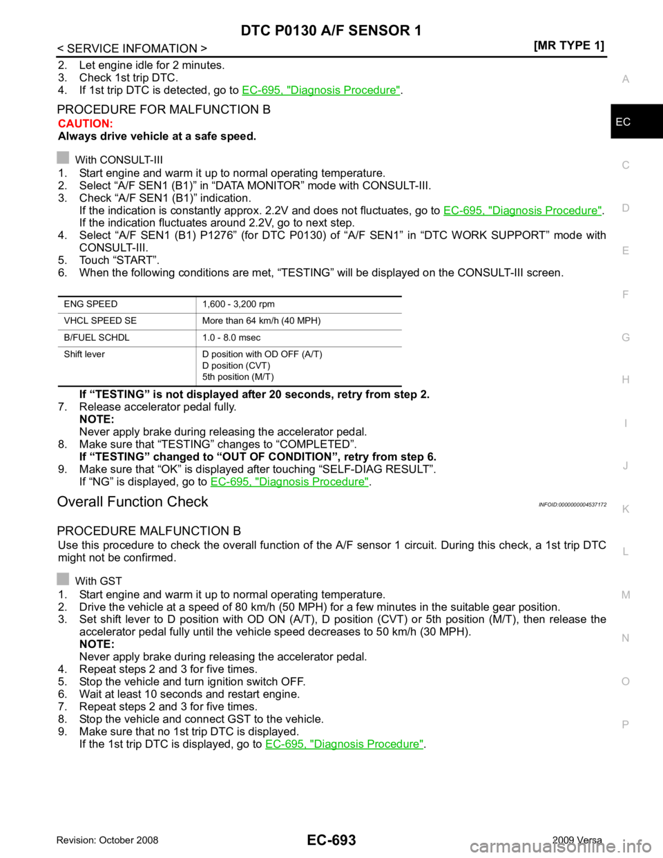
2. Let engine idle for 2 minutes.
3. Check 1st trip DTC.
4. If 1st trip DTC is detected, go to EC-695, " Diagnosis Procedure " .
PROCEDURE FOR MALFUNCTION B CAUTION:
Always drive vehicle at a safe speed.
With CONSULT-III
1. Start engine and warm it up to normal operating temperature.
2. Select “A/F SEN1 (B1)” in “DAT A MONITOR” mode with CONSULT-III.
3. Check “A/F SEN1 (B1)” indication.
If the indication is constantly approx . 2.2V and does not fluctuates, go to EC-695, " Diagnosis Procedure " .
If the indication fluctuates around 2.2V, go to next step.
4. Select “A/F SEN1 (B1) P1276” (for DTC P0130) of “A/F SEN1” in “DTC WORK SUPPORT” mode with
CONSULT-III.
5. Touch “START”.
6. When the following conditions are met, “TESTIN G” will be displayed on the CONSULT-III screen.
If “TESTING” is not displayed after 20 seconds, retry from step 2.
7. Release accelerator pedal fully.
NOTE:
Never apply brake during releasing the accelerator pedal.
8. Make sure that “TESTING” changes to “COMPLETED”.
If “TESTING” changed to “OUT OF CONDITION”, retry from step 6.
9. Make sure that “OK” is display ed after touching “SELF-DIAG RESULT”.
If “NG” is displayed, go to EC-695, " Diagnosis Procedure " .
Overall Function Check INFOID:0000000004537172
PROCEDURE MALFUNCTION B Use this procedure to check the overall function of the A/F sensor 1 circuit. During this check, a 1st trip DTC
might not be confirmed.
With GST
1. Start engine and warm it up to normal operating temperature.
2. Drive the vehicle at a speed of 80 km/h (50 MPH) for a few minutes in the suitable gear position.
3. Set shift lever to D position with OD ON (A/T), D position (CVT) or 5th position (M/T), then release the
accelerator pedal fully until the vehicle speed decreases to 50 km/h (30 MPH).
NOTE:
Never apply brake during releasing the accelerator pedal.
4. Repeat steps 2 and 3 for five times.
5. Stop the vehicle and turn ignition switch OFF.
6. Wait at least 10 seconds and restart engine.
7. Repeat steps 2 and 3 for five times.
8. Stop the vehicle and connect GST to the vehicle.
9. Make sure that no 1st trip DTC is displayed. If the 1st trip DTC is displayed, go to EC-695, " Diagnosis Procedure " .
Page 2055 of 4331

EC
NP
O
If the indication is not constantly approx. 0V, go to next step.
4. Turn ignition switch OFF, wait at least 10 seconds and then restart engine.
5. Drive and accelerate vehicle to more than 40 km/h (25 MPH) within 20 seconds after restarting engine.
6. Maintain the following conditions for about 20 consecutive seconds.
NOTE:
• Keep the accelerator pedal as steady as possible during the cruising.
• If this procedure is not completed within 1 minute after restarting engine at step 4, return to step
4.
7. Check 1st trip DTC.
8. If 1st trip DTC is displayed, go to EC-701, " Diagnosis Procedure " .
WITH GST
Follow the procedure “WITH CONSULT-III” above. ENG SPEED 1,000 - 3,200 rpm
VHCL SPEED SE More than 40 km/h (25 MPH)
B/FUEL SCHDL 1.5 - 9.0 msec
Shift lever Suitable position