2009 NISSAN LATIO wheel torque
[x] Cancel search: wheel torquePage 3788 of 4331
MA
N
O P
Do not overfill.
4. Drive vehicle for approximately 5 minutes.
5. Re-check A/T fluid level at A/T fluid temperatures of 50° to 80 °C (122 ° to 176 °F) using “HOT” range on A/
T fluid level gauge.
CAUTION:
• When wiping the A/T fluid level gauge, always use lint-free cloth.
• Firmly fix the A/T fluid level ga uge to the A/T fluid charging pipe using the stopper attached.
6. Check A/T fluid condition and make any necessary repairs. Refer to AT-51, " Inspections Before Trouble
Diagnosis " . If the A/T fluid contains frictional material (clu
tches, bands, etc.), or if the A/T is repaired, over-
hauled, or replaced, inspect and clean the A/T fluid cooler mounted in the radiator. Refer to AT-18, " A/T
Fluid Cooler Cleaning " .
7. Install the removed A/T fluid level gauge into the A/T fluid charging pipe. CAUTION:
Firmly fix the A/T fluid level gaug e to the A/T fluid charging pipe using the stopper attached.
A/T FLUID : Changing A/T Fluid INFOID:0000000004803431
1. Warm up A/T fluid.
2. Stop engine.
3. Drain A/T fluid by removing the drain plug. Re install the drain plug to the specified torque.
CAUTION:
Do not reuse drain plug gasket.
4. Refill the transaxle with new specified A/T fluid th rough the A/T fluid charging pipe. Always refill the tran-
saxle with the same volume of A/T fluid that was drained out.
5. Run engine at idle speed for 5 minutes.
6. Check A/T fluid level and condition. Refer to MA-44, " A/T FLUID : Checking A/T Fluid " .
WHEELS
WHEELS : Balancing Wheels INFOID:0000000004683837
Adjust wheel balance using road wheel center.
CAUTION:
• Be careful not to scratch th e road wheel during removal.
• Use clip-on type wheel balance weights only.
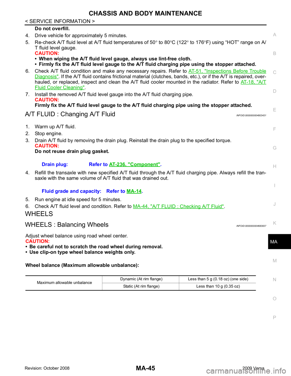
Wheel balance (Maximum allowable unbalance): Drain plug: Refer to
AT-236, " Component " .
Fluid grade and capacity: Refer to MA-14 .
Maximum allowable unbalance Dynamic (At rim flange) Less than 5 g (0.18 oz) (one side)
Static (At rim flange) Less than 10 g (0.35 oz)
Page 3789 of 4331
MA-46< SERVICE INFORMATION >
CHASSIS AND BODY MAINTENANCE
WHEELS : Rotation INFOID:0000000004683838
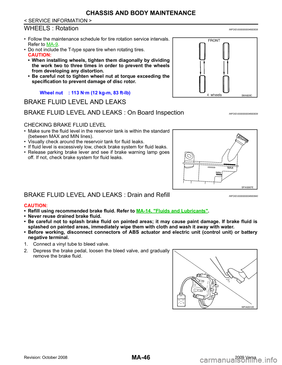
• Follow the maintenance schedule for tire rotation service intervals. Refer to MA-9 .
• Do not include the T-type spare tire when rotating tires.
CAUTION:
• When installing wheels, tighten them diagonally by dividing
the work two to three times in order to prevent the wheels
from developing any distortion.
• Be careful not to tighten wheel nut at torque exceeding the specification to prevent damage of disc rotor.
BRAKE FLUID LEVEL AND LEAKS
BRAKE FLUID LEVEL AND LEAK S : On Board Inspection INFOID:0000000004683839
CHECKING BRAKE FLUID LEVEL
• Make sure the fluid level in the reservoir tank is within the standard (between MAX and MIN lines).
• Visually check around the reservoir tank for fluid leaks.
• If fluid level is excessively low, check brake system for fluid leaks.
• Release parking brake lever and see if brake warning lamp goes off. If not, check brake system for fluid leaks.
BRAKE FLUID LEVEL AND LE AKS : Drain and Refill INFOID:0000000004683840
CAUTION:
• Refill using recommended brake fluid. Refer to MA-14, " Fluids and Lubricants " .
• Never reuse drained brake fluid.
• Be careful not to splash brake fluid on painted areas; it may cause paint damage. If brake fluid is
splashed on painted areas, immediately wipe th em with cloth and wash it away with water.
• Before working, disconnect connectors of ABS actua tor and electric unit (control unit) or battery
negative terminal.
1. Connect a vinyl tube to bleed valve.
2. Depress the brake pedal, loosen the bleed valve, and gradually remove the brake fluid.Wheel nut : 113 N·m (12 kg-m, 83 ft-lb) SMA829C
SFIA3067E
WFIA0512E
Page 4060 of 4331
PS-4< SERVICE INFORMATION >
PREPARATION
PREPARATION
Special Service Tool INFOID:0000000004305928
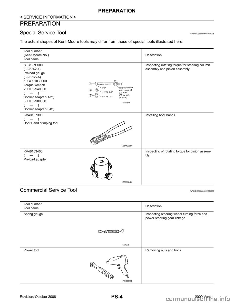
The actual shapes of K ent-Moore tools may differ from thos e of special tools illustrated here.
Commercial Service Tool INFOID:0000000004305929
Tool number
(Kent-Moore No.)
Tool name Description
ST3127S000
(J-25742-1)
Preload gauge
(J-25765-A)
1. GG91030000
Torque wrench
2. HT62940000
( — )
Socket adapter (1/2")
3. HT62900000
( — )
Socket adapter (3/8") Inspecting rotating torque for steering column
assembly and pinion assembly
KV40107300
( — )
Boot Band crimping tool Installing boot bands
KV48103400
( — )
Preload adapter Inspecting of rotating torque for pinion assem-
bly S-NT541
ZZA1229D
ZZA0824D
Tool number
Tool name Description
Spring gauge Inspecting steering wheel turning force and
power steering gear linkage
Power tool Removing nuts and bolts LST025
PBIC0190E
Page 4061 of 4331
PS
N
O P
NOISE, VIBRATION AND HARSHN
ESS (NVH) TROUBLESHOOTING
NVH Troubleshooting Chart INFOID:0000000004305930
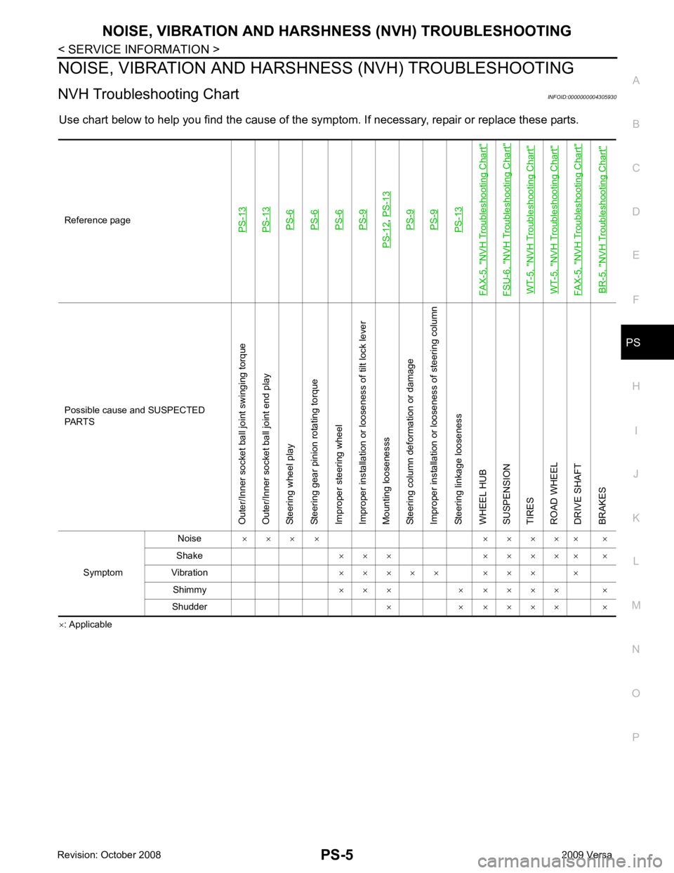
Use chart below to help you find the cause of the symptom. If necessary, repair or replace these parts.
× : ApplicableReference pagePS-13PS-13PS-6PS-6PS-6PS-9
PS-12
,
PS-13PS-9PS-9PS-13
FAX-5, "
NVH Troubleshooting Chart
"
FSU-6, "
NVH Troubleshooting Chart
"
WT-5, "
NVH Troubleshooting Chart
"
WT-5, "
NVH Troubleshooting Chart
"
FAX-5, "
NVH Troubleshooting Chart
"
BR-5, "
NVH Troubleshooting Chart
" Possible cause and SUSPECTED
PARTS
Outer/Inner socket ball joint swinging torque
Outer/Inner socket ball joint end play
Steering wheel play
Steering gear pinion rotating torque
Improper steering wheel
Improper installation or looseness of tilt lock lever
Mounting loosenesss
Steering column deformation or damage
Improper installation or looseness of steering column
Steering linkage looseness
WHEEL HUB
SUSPENSION
TIRES
ROAD WHEEL
DRIVE SHAFT
BRAKES
Symptom Noise
× × × × × × × × × ×
Shake × × × × × × × × ×
Vibration × × × × × × × × ×
Shimmy × × × × × × × × ×
Shudder × × × × × × ×
Page 4071 of 4331
PS
N
O P
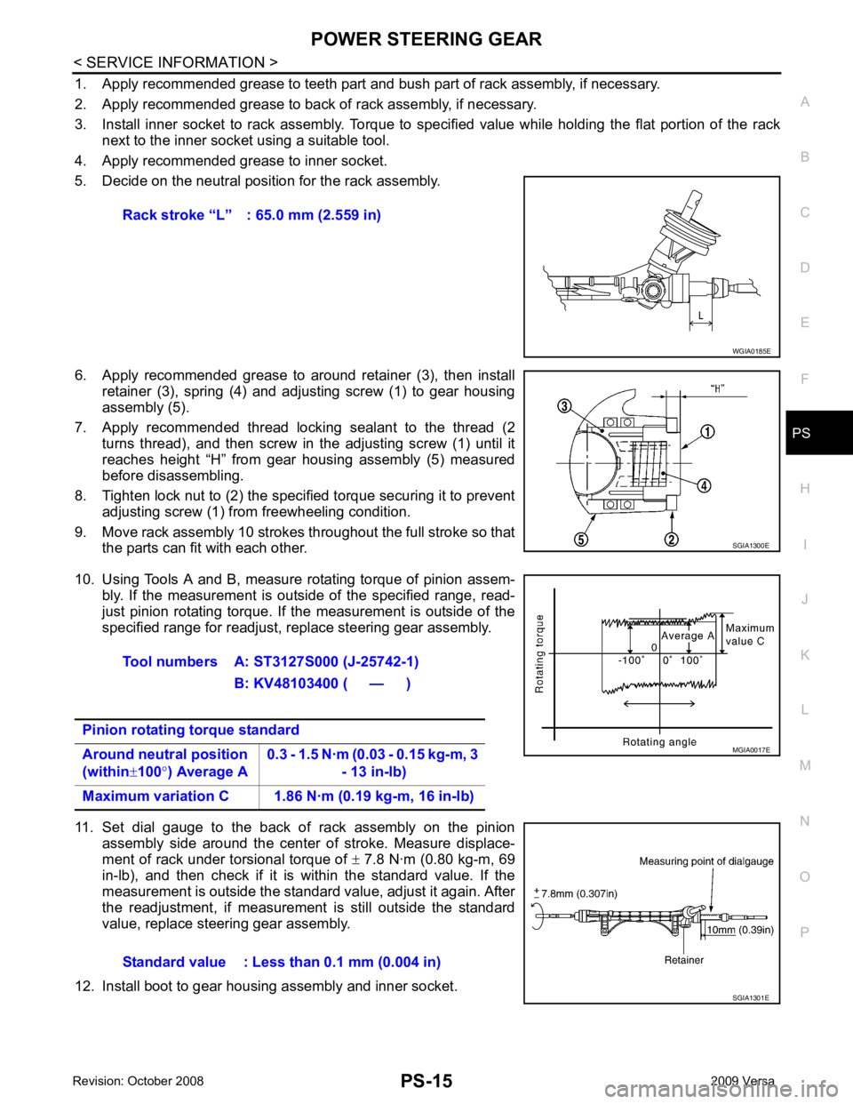
1. Apply recommended grease to teeth part and bush part of rack assembly, if necessary.
2. Apply recommended grease to back of rack assembly, if necessary.
3. Install inner socket to rack assembly. Torque to specified value while holding the flat portion of the rack next to the inner socket using a suitable tool.
4. Apply recommended grease to inner socket.
5. Decide on the neutral position for the rack assembly.
6. Apply recommended grease to around retainer (3), then install retainer (3), spring (4) and adjusting screw (1) to gear housing
assembly (5).
7. Apply recommended thread locking sealant to the thread (2 turns thread), and then screw in the adjusting screw (1) until it
reaches height “H” from gear housing assembly (5) measured
before disassembling.
8. Tighten lock nut to (2) the specified torque securing it to prevent adjusting screw (1) from freewheeling condition.
9. Move rack assembly 10 strokes throughout the full stroke so that the parts can fit with each other.
10. Using Tools A and B, measure rotating torque of pinion assem- bly. If the measurement is outside of the specified range, read-
just pinion rotating torque. If the measurement is outside of the
specified range for readjust, replace steering gear assembly.
11. Set dial gauge to the back of rack assembly on the pinion assembly side around the center of stroke. Measure displace-
ment of rack under torsional torque of ± 7.8 N·m (0.80 kg-m, 69
in-lb), and then check if it is within the standard value. If the
measurement is outside the standard value, adjust it again. After
the readjustment, if measurement is still outside the standard
value, replace steering gear assembly.
12. Install boot to gear housing assembly and inner socket. Rack stroke “L” : 65.0 mm (2.559 in)
Page 4073 of 4331
SERVICE DATA AND SPECIFICATIONS (SDS)
PS-17
< SERVICE INFORMATION >
C
D E
F
H I
J
K L
M A
B PS
N
O
P
SERVICE DATA AND SPECIFICATIONS (SDS)
Steering Wheel INFOID:0000000004305936
Steering Angle INFOID:0000000004305937
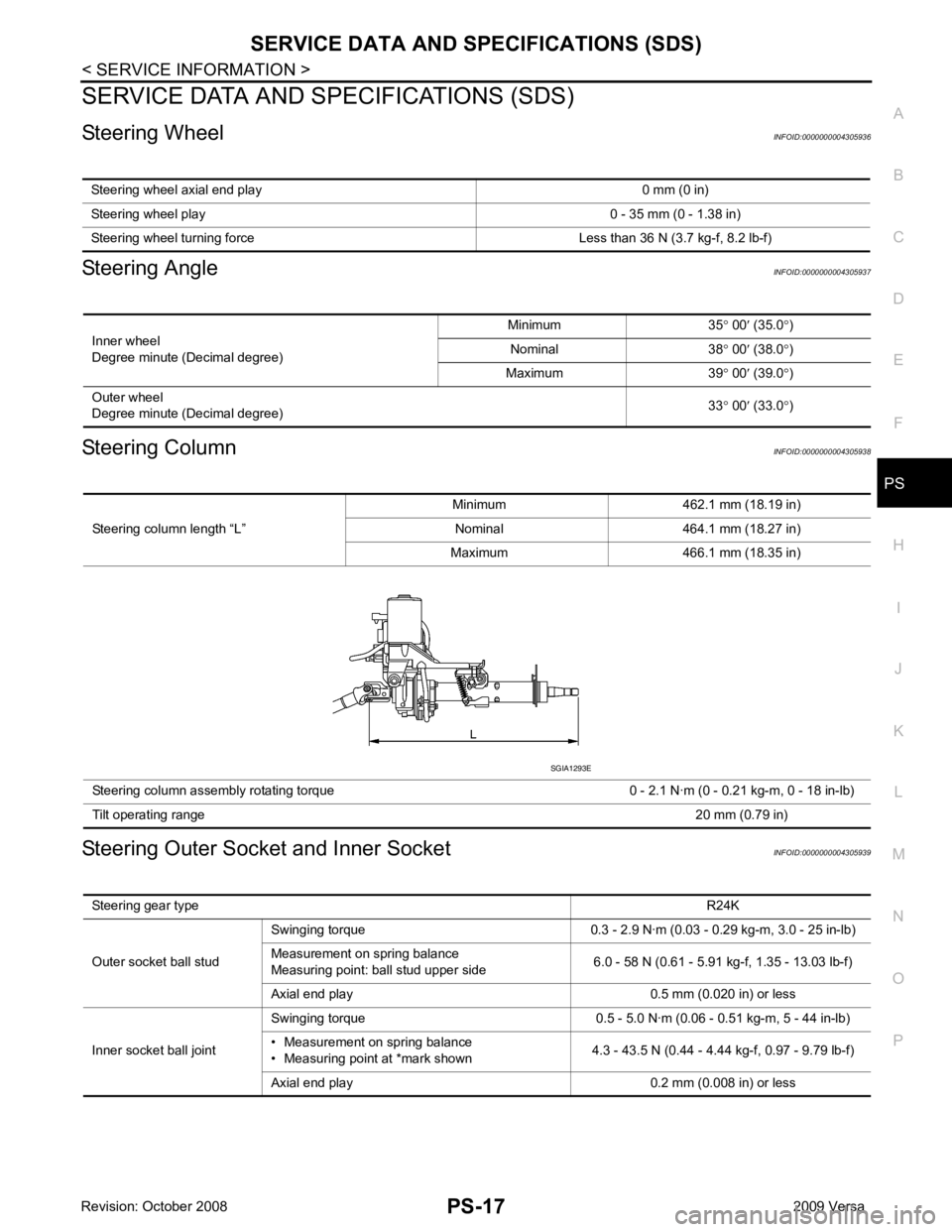
Steering Column INFOID:0000000004305938
Steering Outer Socket and Inner Socket INFOID:0000000004305939
Steering wheel axial end play 0 mm (0 in)
Steering wheel play 0 - 35 mm (0 - 1.38 in)
Steering wheel turning force Less than 36 N (3.7 kg-f, 8.2 lb-f) Inner wheel
Degree minute (Decimal degree) Minimum 35
° 00 ′ (35.0 °)
Nominal 38 ° 00 ′ (38.0 °)
Maximum 39 ° 00 ′ (39.0 °)
Outer wheel
Degree minute (Decimal degree) 33
° 00 ′ (33.0 °) Steering column length “L”
Minimum 462.1 mm (18.19 in)
Nominal 464.1 mm (18.27 in)
Maximum 466.1 mm (18.35 in)
Steering column assembly rotating torque 0 - 2.1 N·m (0 - 0.21 kg-m, 0 - 18 in-lb)
Tilt operating range 20 mm (0.79 in)SGIA1293E
Steering gear type R24K
Outer socket ball stud Swinging torque 0.3 - 2.9 N·m (0.03 - 0.29 kg-m, 3.0 - 25 in-lb)
Measurement on spring balance
Measuring point: ball stud upper side 6.0 - 58 N (0.61 - 5.91 kg-f, 1.35 - 13.03 lb-f)
Axial end play 0.5 mm (0.020 in) or less
Inner socket ball joint Swinging torque 0.5 - 5.0 N·m (0.06 - 0.51 kg-m, 5 - 44 in-lb)
• Measurement on spring balance
• Measuring point at *mark shown 4.3 - 43.5 N (0.44 - 4.44 kg-f, 0.97 - 9.79 lb-f)
Axial end play 0.2 mm (0.008 in) or less
Page 4120 of 4331
RSU
N
O P
SHOCK ABSORBER
Removal and Installation INFOID:0000000004305881
REMOVAL 1. Remove wheel and tire using power tool.
2. Remove wheel sensor from wheel hub and bearing assembly and rear suspension beam. Refer to BRC-32 .
CAUTION:
Do not pull on wheel sensor harness.
3. Remove shock absorber mask from trunk side fini sher using a flat-bladed screwdriver. Refer to EI-53 .
CAUTION:
Wrap the tip of a screwdriver with cl oth to avoid damaging components.
4. Set jack under rear suspension beam.
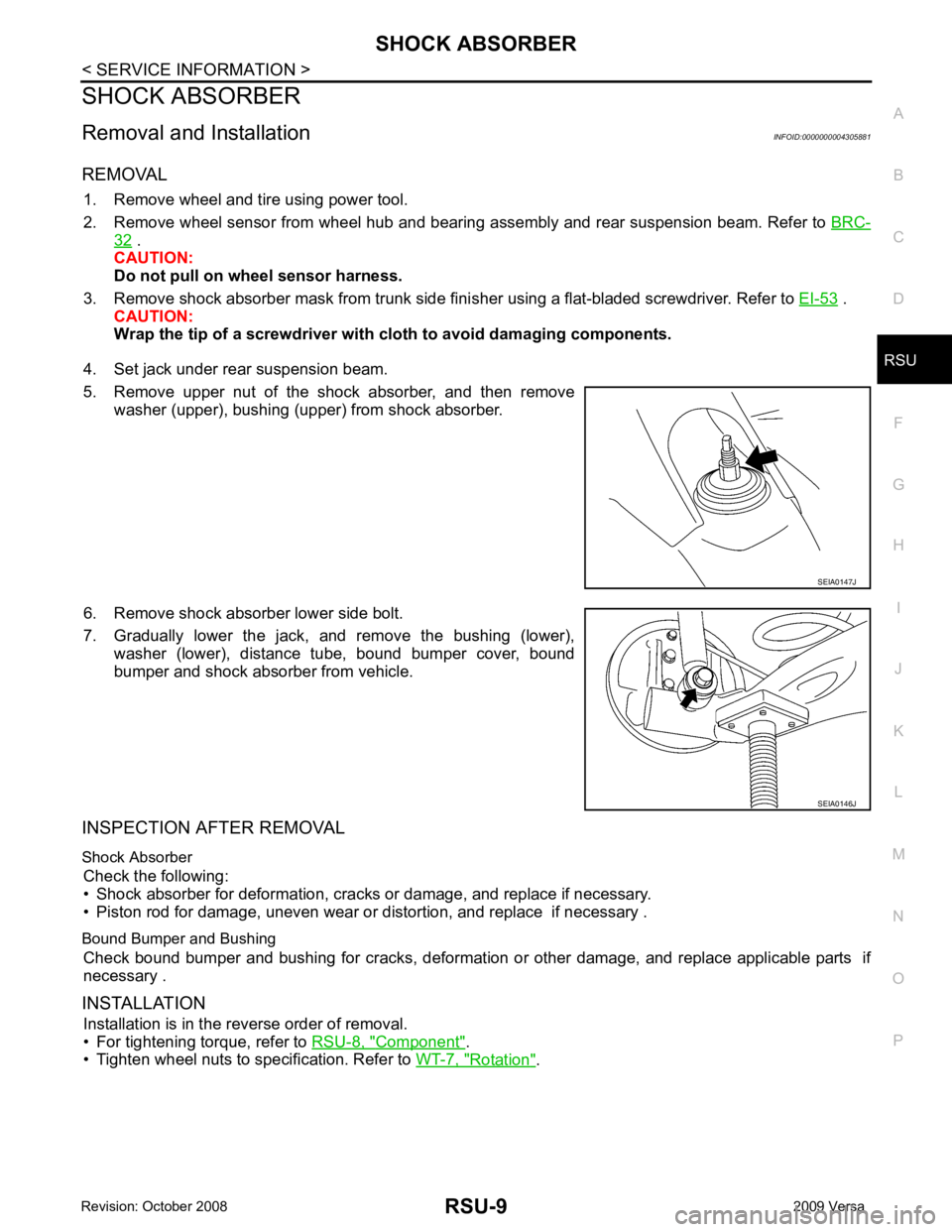
5. Remove upper nut of the shock absorber, and then remove washer (upper), bushing (upper) from shock absorber.
6. Remove shock absorber lower side bolt.
7. Gradually lower the jack, and remove the bushing (lower), washer (lower), distance tube, bound bumper cover, bound
bumper and shock absorber from vehicle.
INSPECTION AFTER REMOVAL
Shock Absorber Check the following:
• Shock absorber for deformation, cracks or damage, and replace if necessary.
• Piston rod for damage, uneven wear or di stortion, and replace if necessary .
Bound Bumper and Bushing Check bound bumper and bushing for cracks, deformation or other damage, and replace applicable parts if
necessary .
INSTALLATION Installation is in the reverse order of removal.
• For tightening torque, refer to RSU-8, " Component " .
• Tighten wheel nuts to specification. Refer to WT-7, " Rotation " .
Page 4122 of 4331
COIL SPRING
RSU-11
< SERVICE INFORMATION >
C
D
F
G H
I
J
K L
M A
B RSU
N
O P
COIL SPRING
Removal and Installation INFOID:0000000004305882
REMOVAL 1. Remove wheel and tire using power tool.
2. Remove wheel sensor from wheel hub and bearing assembly. Refer to BRC-32, " Removal and Installa-
tion " .
CAUTION:
Do not pull on wheel sensor harness.
3. Separate brake tube from wheel cylinder. Refer to BR-12, " Rear Brake Tube and Hose " .
4. Set jack under rear suspension beam.
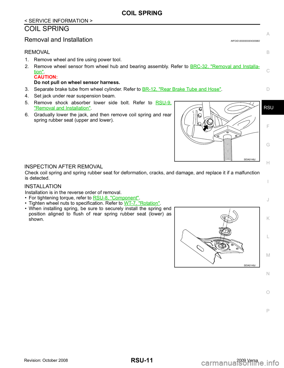
5. Remove shock absorber lower side bolt. Refer to RSU-9," Removal and Installation " .
6. Gradually lower the jack, and then remove coil spring and rear spring rubber seat (upper and lower).
INSPECTION AFTER REMOVAL Check coil spring and spring rubber seat for deformation, cracks, and damage, and replace it if a malfunction
is detected.
INSTALLATION Installation is in the reverse order of removal.
• For tightening torque, refer to RSU-8, " Component " .
• Tighten wheel nuts to specification. Refer to WT-7, " Rotation " .
• When installing spring, be sure to securely install the spring end
position aligned to flush of rear spring rubber seat (lower) as
shown. SEIA0146J
SEIA0149J