2009 NISSAN LATIO oil change
[x] Cancel search: oil changePage 2443 of 4331
![NISSAN LATIO 2009 Service Repair Manual BASIC SERVICE PROCEDURE
EC-1087
< SERVICE INFOMATION >
[MR TYPE 2] C
D E
F
G H
I
J
K L
M A EC
NP
O
1. Remove fuel pump fuse (1) located in IPDM E/R (2).
• : Vehicle front
2. Start engine.
3. After e NISSAN LATIO 2009 Service Repair Manual BASIC SERVICE PROCEDURE
EC-1087
< SERVICE INFOMATION >
[MR TYPE 2] C
D E
F
G H
I
J
K L
M A EC
NP
O
1. Remove fuel pump fuse (1) located in IPDM E/R (2).
• : Vehicle front
2. Start engine.
3. After e](/manual-img/5/57359/w960_57359-2442.png)
BASIC SERVICE PROCEDURE
EC-1087
< SERVICE INFOMATION >
[MR TYPE 2] C
D E
F
G H
I
J
K L
M A EC
NP
O
1. Remove fuel pump fuse (1) located in IPDM E/R (2).
• : Vehicle front
2. Start engine.
3. After engine stalls, crank it two or three times to release all fuel pressure.
4. Turn ignition switch OFF.
5. Reinstall fuel pump fuse after servicing fuel system.
FUEL PRESSURE CHECK CAUTION:
Before disconnecting fuel line, release fuel pressure from fuel line to eliminate danger.
NOTE:
• Prepare pans or saucers under the disconnected fuel line because the fuel may spill out. The fuel
pressure cannot be completely released because C11 models do not have fuel return system.
• The fuel hose connection method u sed when taking fuel pressure check must not be used for other
purposes.
• Be careful not to scratch or put debris around connection area when servicing, so that the quick
connector maintains seal abil ity with O-rings inside.
• Do not perform fuel pressure check with electrical syst ems operating (i.e. lights, rear defogger, A/C,
etc.) Fuel pressure gauge may indicate false readin gs due to varying engine load and changes in
manifold vacuum.
1. Release fuel pressure to zero. Refer to "FUEL PRESSURE RELEASE".
2. Prepare fuel hose for fuel pressure check B and fuel tube adapter (KV10118400) D, then connect fuel pressure gauge A.
• : To quick connector
• : To fuel tube (engine side)
• C: Clamp
• Use suitable fuel hose for fuel pressure check (genuine
NISSAN fuel hose without quick connector).
• To avoid unnecessary force or tension to hose, use moder- ately long fuel hose for fuel pressure check.
• Do not use the fuel hose for checking fuel pressure with dam- age or cracks on it.
• Use Pressure Gauge to check fuel pressure.
3. Remove fuel hose. Refer to EM-156, " Removal and Installation " .
• Do not twist or kink fuel hose because it is plastic hose.
4. Connect fuel hose for fuel pressure check (1) to fuel tube (engine side) with clamp (2) as shown in the figure.
• No.2 spool (5)
• Wipe off oil or dirt from hose insertion part using cloth moist-
ened with gasoline.
• Apply proper amount of gasoline between top of the fuel tube (3) and No.1 spool (4).
• Insert fuel hose for fuel pressure check until it touches the No.1 spool on fuel tube.
• Use NISSAN genuine hose clamp (part number: 16439 N4710
or 16439 40U00).
• When reconnecting fuel line, always use new clamps.
• Use a torque driver to tighten clamps.
• Install hose clamp to the positi on within 1 - 2 mm (0.04 - 0.08 in).
• Make sure that clamp screw does not contact adjacent parts. PBIB2958E
Tightening torque: 1 - 1.5 N·m
(0.1 - 0.15 kg-m, 9 - 13 in-lb) PBIB2982E
PBIB2983E
Page 2479 of 4331
![NISSAN LATIO 2009 Service Repair Manual EC
NP
O
NOTE:
Any monitored item that does not match the vehicle being diagnosed is deleted from the display automatically.
ACTIVE TEST MODE
Test Item AT OD CANCEL
[ON/OFF] • Indicates [ON/OFF] cond NISSAN LATIO 2009 Service Repair Manual EC
NP
O
NOTE:
Any monitored item that does not match the vehicle being diagnosed is deleted from the display automatically.
ACTIVE TEST MODE
Test Item AT OD CANCEL
[ON/OFF] • Indicates [ON/OFF] cond](/manual-img/5/57359/w960_57359-2478.png)
EC
NP
O
NOTE:
Any monitored item that does not match the vehicle being diagnosed is deleted from the display automatically.
ACTIVE TEST MODE
Test Item AT OD CANCEL
[ON/OFF] • Indicates [ON/OFF] condition of A/T O/D cancel signal sent
from the TCM. • For M/T models always “OFF” is displayed
CRUISE LAMP
[ON/OFF] • Indicates [ON/OFF]
condition of CRUISE lamp determined
by the ECM according to the input signals.
SET LAMP
[ON/OFF] • Indicates [ON/OFF] condition of SET lamp determined by the
ECM according to the input signals.
A/F ADJ-B1 • Indicates the correction factor stored in ECM. The factor is
calculated from the difference between the target air/fuel ratio
stored in ECM and the air/fuel ratio calculated from air fuel ra-
tio (A/F) sensor 1 signal.
Monitored item [Unit] Description Remarks TEST ITEM CONDITION JUDGMENT CHECK ITEM (REMEDY)
FUEL INJEC-
TION • Engine: Return to the original
trouble condition
• Change the amount of fuel injec- tion using CONSULT-III. If trouble symptom disappears, see
CHECK ITEM. • Harness and connectors
• Fuel injector
• Air fuel ratio (A/F) sensor 1
IGNITION TIM-
ING • Engine: Return to the original
trouble condition
• Timing light: Set
• Retard the ignition timing using
CONSULT-III. If trouble symptom disappears, see
CHECK ITEM. • Perform Idle Air Volume Learning.
POWER BAL-
ANCE • Engine: After warming up, idle the
engine.
• A/C switch OFF
• Shift lever: P or N (A/T, CVT), Neutral (M/T)
• Cut off each fuel injector signal
one at a time using CONSULT-III. Engine runs rough or dies.
• Harness and connectors
• Compression
• Fuel injector
• Power transistor
• Spark plug
• Ignition coil
COOLING FAN* • Ignition switch: ON
• Turn the cooling fan “LOW”, “HI” and “OFF” with CONSULT-III. Cooling fan moves and stops. • Harness and connectors
• Cooling fan relay
• Cooling fan motor
ENG COOLANT
TEMP • Engine: Return to the original
trouble condition
• Change the engine coolant tem- perature using CONSULT-III. If trouble symptom disappears, see
CHECK ITEM. • Harness and connectors
• Engine coolant temperature sen-
sor
• Fuel injector
FUEL PUMP RE-
LAY • Ignition switch: ON
(Engine stopped)
• Turn the fuel pump relay ON and OFF using CONSULT-III and lis-
ten to operating sound. Fuel pump relay makes the operat-
ing sound. • Harness and connectors
• Fuel pump relay
PURG VOL
CONT/V • Engine: After warming up, run en-
gine at 1,500 rpm.
• Change the EVAP canister purge volume control solenoid valve
opening percent using CON-
SULT-III. Engine speed changes according to
the opening percent. • Harness and connectors
• EVAP canister purge volume con- trol solenoid valve
FUEL/T TEMP
SEN • Change the fuel tank temperature using CONSULT-III.
Page 2521 of 4331
![NISSAN LATIO 2009 Service Repair Manual DTC P0075 IVT CONTROL SOLENOID VALVE
EC-1165
< SERVICE INFOMATION >
[MR TYPE 2] C
D E
F
G H
I
J
K L
M A EC
NP
O
DTC P0075 IVT CONTROL SOLENOID VALVE
Component Description INFOID:0000000004499990
Intak NISSAN LATIO 2009 Service Repair Manual DTC P0075 IVT CONTROL SOLENOID VALVE
EC-1165
< SERVICE INFOMATION >
[MR TYPE 2] C
D E
F
G H
I
J
K L
M A EC
NP
O
DTC P0075 IVT CONTROL SOLENOID VALVE
Component Description INFOID:0000000004499990
Intak](/manual-img/5/57359/w960_57359-2520.png)
DTC P0075 IVT CONTROL SOLENOID VALVE
EC-1165
< SERVICE INFOMATION >
[MR TYPE 2] C
D E
F
G H
I
J
K L
M A EC
NP
O
DTC P0075 IVT CONTROL SOLENOID VALVE
Component Description INFOID:0000000004499990
Intake valve timing control solenoid valve is activated by ON/OFF
pulse duty (ratio) signals from the ECM.
The intake valve timing control solenoid valve changes the oil
amount and direction of flow through intake valve timing control unit
or stops oil flow.
The longer pulse width advances valve angle.
The shorter pulse width retards valve angle.
When ON and OFF pulse widths become equal, the solenoid valve
stops oil pressure flow to fix the intake valve angle at the control
position.
CONSULT-III Reference Val ue in Data Monitor Mode INFOID:0000000004499991
Specification data are reference values.
On Board Diagnosis Logic INFOID:0000000004499992
DTC Confirmation Procedure INFOID:0000000004499993
NOTE:
If DTC Confirmation Procedure h as been previously conducted, alw ays turn ignition switch OFF and
wait at least 10 seconds before conducting the next test.
1. Start engine and let it idle for 5 seconds.
2. Check 1st trip DTC.
3. If 1st trip DTC is detected, go to EC-1167, " Diagnosis Procedure " . PBIB1842E
MONITOR ITEM CONDITION SPECIFICATION
INT/V SOL (B1) • Engine: After warming up
• Air conditioner switch: OFF
• Shift lever: P or N (A/T, CVT), Neu-
tral (M/T)
• No load Idle 0% - 2%
When revving engine up to 2,000 rpm
quickly Approx. 0% - 90%DTC No. Trouble diagnosis name DTC detecting condition Possible cause
P0075
0075 Intake valve timing control
solenoid valve circuit An improper voltage is sent to the ECM
through intake valve timing control solenoid
valve. • Harness or connectors
(Intake valve timing control solenoid valve
circuit is open or shorted.)
• Intake valve timing control solenoid valve
Page 2994 of 4331

EM
NP
O
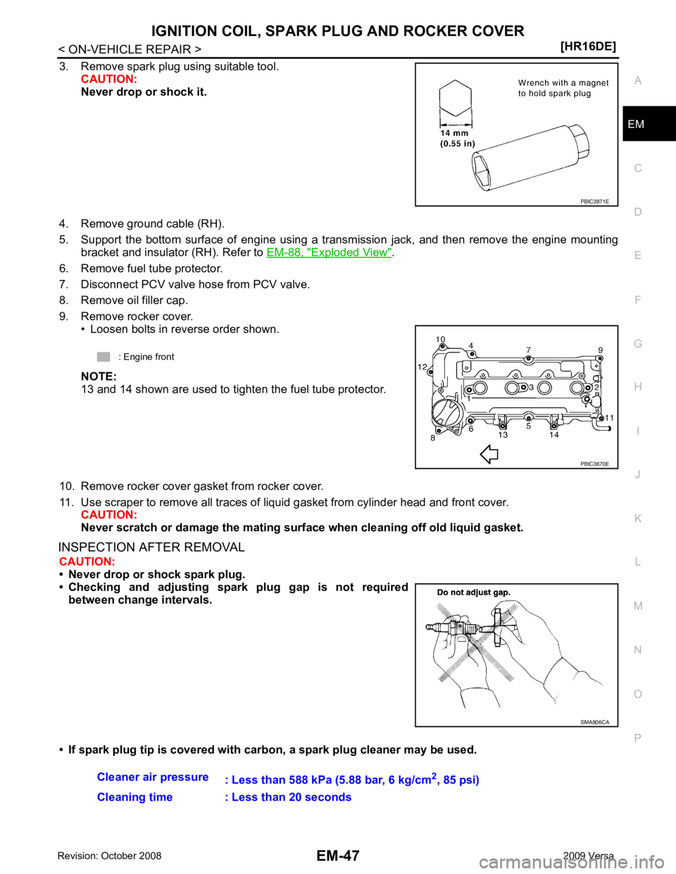
3. Remove spark plug using suitable tool.
CAUTION:
Never drop or shock it.
4. Remove ground cable (RH).
5. Support the bottom surface of engine using a trans mission jack, and then remove the engine mounting
bracket and insulator (RH). Refer to EM-88, " Exploded View " .
6. Remove fuel tube protector.
7. Disconnect PCV valve hose from PCV valve.
8. Remove oil filler cap.
9. Remove rocker cover. • Loosen bolts in reverse order shown.
NOTE:
13 and 14 shown are used to tighten the fuel tube protector.
10. Remove rocker cover gasket from rocker cover.
11. Use scraper to remove all traces of liquid gasket from cylinder head and front cover.
CAUTION:
Never scratch or damage the mating su rface when cleaning off old liquid gasket.
INSPECTION AFTER REMOVAL CAUTION:
• Never drop or shock spark plug.
• Checking and adjusting spar k plug gap is not required
between change intervals.
• If spark plug tip is covered with carbon, a spark plug cleaner may be used. SMA806CA
Page 3038 of 4331

EM
NP
O
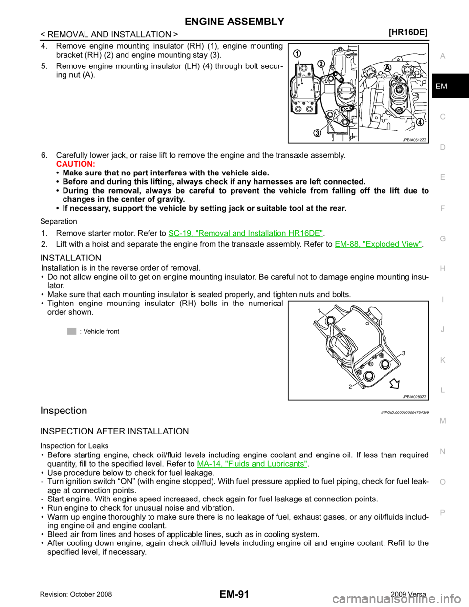
4. Remove engine mounting insulator (RH) (1), engine mounting
bracket (RH) (2) and engine mounting stay (3).
5. Remove engine mounting insulator (LH) (4) through bolt secur- ing nut (A).
6. Carefully lower jack, or raise lift to remove the engine and the transaxle assembly. CAUTION:
• Make sure that no part interferes with the vehicle side.
• Before and during this lifting, alw ays check if any harnesses are left connected.
• During the removal, always be careful to prevent the vehicle from falling off the lift due to
changes in the center of gravity.
• If necessary, support the vehicle by setting jack or suitable tool at the rear.
Separation 1. Remove starter motor. Refer to SC-19, " Removal and Installation HR16DE " .
2. Lift with a hoist and separate the engine from the transaxle assembly. Refer to EM-88, " Exploded View " .
INSTALLATION Installation is in the reverse order of removal.
• Do not allow engine oil to get on engine mounting insulator. Be careful not to damage engine mounting insu- lator.
• Make sure that each mounting insulator is seated properly, and tighten nuts and bolts.
• Tighten engine mounting insulator (RH) bolts in the numerical
order shown.
Inspection INFOID:0000000004784309
INSPECTION AFTER INSTALLATION
Inspection for Leaks • Before starting engine, check oil/fluid levels incl uding engine coolant and engine oil. If less than required
quantity, fill to the specified level. Refer to MA-14, " Fluids and Lubricants " .
• Use procedure below to check for fuel leakage.
- Turn ignition switch “ON” (with engine stopped). With fuel pressure applied to fuel piping, check for fuel leak-
age at connection points.
- Start engine. With engine speed increased, check again for fuel leakage at connection points.
• Run engine to check for unusual noise and vibration.
• Warm up engine thoroughly to make sure there is no leak age of fuel, exhaust gases, or any oil/fluids includ-
ing engine oil and engine coolant.
• Bleed air from lines and hoses of applicable lines, such as in cooling system.
• After cooling down engine, again check oil/fluid levels including engine oil and engine coolant. Refill to the specified level, if necessary.
Page 3101 of 4331
![NISSAN LATIO 2009 Service Repair Manual EM-154< SERVICE INFORMATION >
[MR18DE]
IGNITION COIL, SPARK PLUG AND ROCKER COVER
3. Remove spark plug using suitable tool. CAUTION:
Never drop or shock it.
4. Remove rocker cover. • Loosen bolts in NISSAN LATIO 2009 Service Repair Manual EM-154< SERVICE INFORMATION >
[MR18DE]
IGNITION COIL, SPARK PLUG AND ROCKER COVER
3. Remove spark plug using suitable tool. CAUTION:
Never drop or shock it.
4. Remove rocker cover. • Loosen bolts in](/manual-img/5/57359/w960_57359-3100.png)
EM-154< SERVICE INFORMATION >
[MR18DE]
IGNITION COIL, SPARK PLUG AND ROCKER COVER
3. Remove spark plug using suitable tool. CAUTION:
Never drop or shock it.
4. Remove rocker cover. • Loosen bolts in reverse order as shown.
• Engine front
INSPECTION AFTER REMOVAL
CAUTION:
• Never drop or shock spark plug.
• Checking and adjusting spar k plug gap is not required
between change intervals.
• If spark plug tip is covered with car bon, a spark plug cleaner may be used.
• Never use wire brush for cleaning spark plug.
INSTALLATION
1. Install the rocker cover gasket to the rocker cover. PBIC3871E
PBIC3151J
SMA806CA
Cleaner air pressure
: Less than 588 kPa (5.88 bar, 6 kg/cm 2
, 85 psi)
Cleaning time : Less than 20 seconds SMA773C
Page 3144 of 4331

EM
NP
O
24. Remove A/C compressor with piping connected from t
he engine. Temporarily secure it on the vehicle side
with a rope to avoid putting load on it. Refer to MTC-80, " Removal and Installation of Compressor -
MR18DE " .
25. Remove the intake manifold to prevent the hanging chain from interfering. Refer to EM-141, " Compo-
nent " .
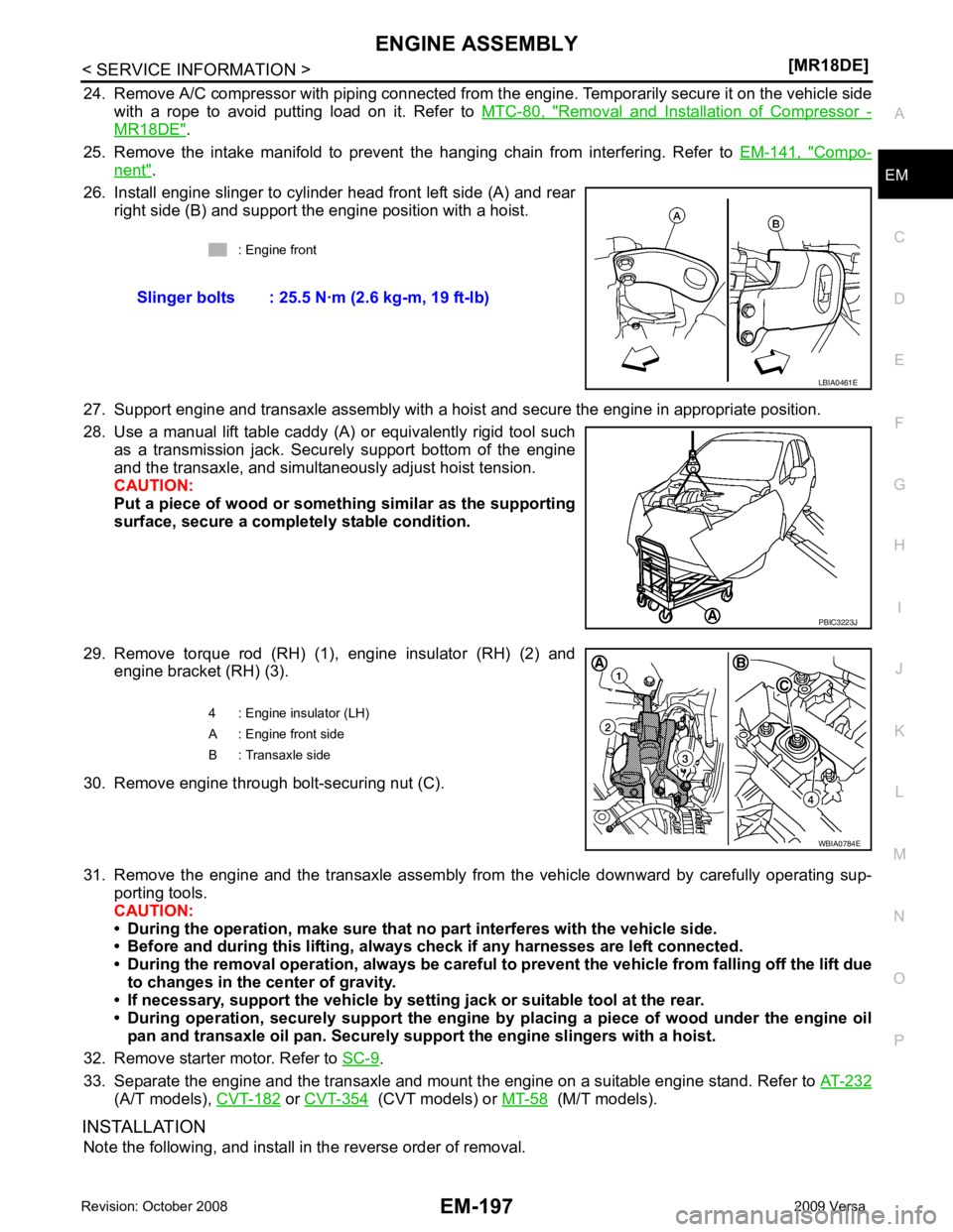
26. Install engine slinger to cylinder head front left side (A) and rear right side (B) and support the engine position with a hoist.
27. Support engine and transaxle assembly with a hoist and secure the engine in appropriate position.
28. Use a manual lift table caddy (A) or equivalently rigid tool such as a transmission jack. Securely support bottom of the engine
and the transaxle, and simultaneously adjust hoist tension.
CAUTION:
Put a piece of wood or someth ing similar as the supporting
surface, secure a completely stable condition.
29. Remove torque rod (RH) (1), engine insulator (RH) (2) and engine bracket (RH) (3).
30. Remove engine through bolt-securing nut (C).
31. Remove the engine and the transaxle assembly from the vehicle downward by carefully operating sup- porting tools.
CAUTION:
• During the operation, make sure that no part interferes with the vehicle side.
• Before and during this lifting, alw ays check if any harnesses are left connected.
• During the removal operation, alw ays be careful to prevent the vehicle from falling off the lift due
to changes in the center of gravity.
• If necessary, support the vehicle by setting jack or suitable tool at the rear.
• During operation, securely suppor t the engine by placing a piece of wood under the engine oil
pan and transaxle oil pan. Securely sup port the engine slingers with a hoist.
32. Remove starter motor. Refer to SC-9 .
33. Separate the engine and the transaxle and mount the engine on a suitable engine stand. Refer to AT-232(A/T models),
CVT-182 or
CVT-354 (CVT models) or
MT-58 (M/T models).
INSTALLATION Note the following, and install in the reverse order of removal. : Engine front
Slinger bolts : 25.5 N·m (2.6 kg-m, 19 ft-lb) PBIC3223J
Page 3286 of 4331

GI
N
O P
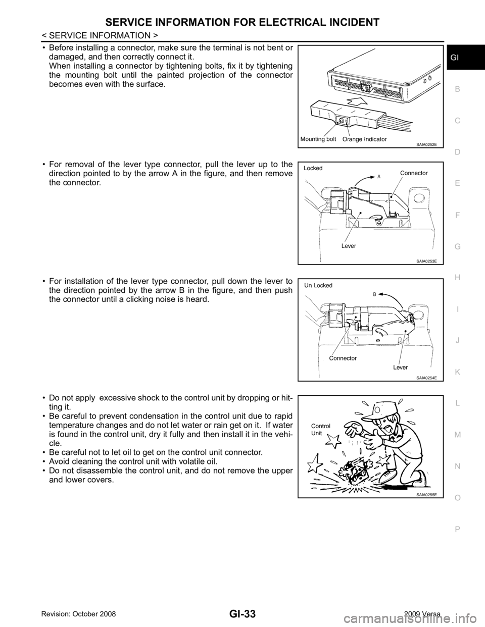
• Before installing a connector, make sure the terminal is not bent or
damaged, and then correctly connect it.
When installing a connector by tightening bolts, fix it by tightening
the mounting bolt until the painted projection of the connector
becomes even with the surface.
• For removal of the lever type connector, pull the lever up to the direction pointed to by the arrow A in the figure, and then remove
the connector.
• For installation of the lever type connector, pull down the lever to the direction pointed by the arrow B in the figure, and then push
the connector until a clicking noise is heard.
• Do not apply excessive shock to the control unit by dropping or hit- ting it.
• Be careful to prevent condensation in the control unit due to rapid
temperature changes and do not let water or rain get on it. If water
is found in the control unit, dry it fully and then install it in the vehi-
cle.
• Be careful not to let oil to get on the control unit connector.
• Avoid cleaning the control unit with volatile oil.
• Do not disassemble the control unit, and do not remove the upper
and lower covers.