2009 NISSAN LATIO oil change
[x] Cancel search: oil changePage 77 of 4331

,
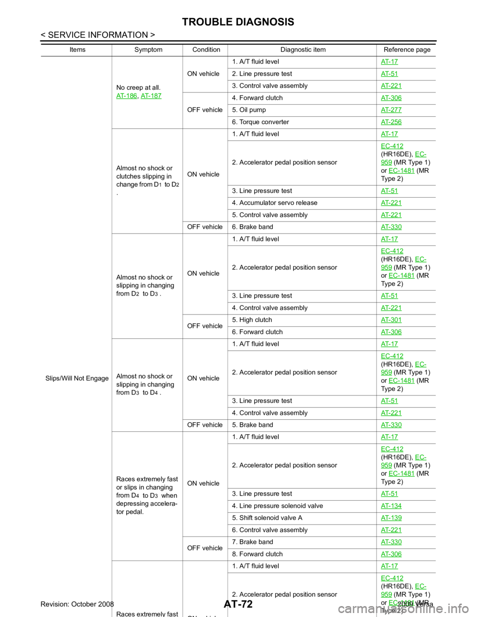
AT-187 ON vehicle
1. A/T fluid level
AT-17 2. Line pressure test
AT-51 3. Control valve assembly
AT-221 OFF vehicle
4. Forward clutch
AT-306 5. Oil pump
AT-277 6. Torque converter
AT-256Almost no shock or
clutches slipping in
change from D 1 to D 2
. ON vehicle1. A/T fluid level
AT-17 2. Accelerator pedal position sensor
EC-412
(HR16DE), EC- 959 (MR Type 1)
or EC-1481 (MR
Type 2)
3. Line pressure test AT-51 4. Accumulator servo release
AT-221 5. Control valve assembly
AT-221 OFF vehicle 6. Brake band
AT-330Almost no shock or
slipping in changing
from D 2 to D 3 . ON vehicle 1. A/T fluid level
AT-17 2. Accelerator pedal position sensor
EC-412
(HR16DE), EC- 959 (MR Type 1)
or EC-1481 (MR
Type 2)
3. Line pressure test AT-51 4. Control valve assembly
AT-221 OFF vehicle
5. High clutch
AT-301 6. Forward clutch
AT-306Almost no shock or
slipping in changing
from D 3 to D 4 . ON vehicle 1. A/T fluid level
AT-17 2. Accelerator pedal position sensor
EC-412
(HR16DE), EC- 959 (MR Type 1)
or EC-1481 (MR
Type 2)
3. Line pressure test AT-51 4. Control valve assembly
AT-221 OFF vehicle 5. Brake band
AT-330Races extremely fast
or slips in changing
from D 4 to D 3 when
depressing accelera-
tor pedal. ON vehicle1. A/T fluid level
AT-17 2. Accelerator pedal position sensor
EC-412
(HR16DE), EC- 959 (MR Type 1)
or EC-1481 (MR
Type 2)
3. Line pressure test AT-51 4. Line pressure solenoid valve
AT-134 5. Shift solenoid valve A
AT-139 6. Control valve assembly
AT-221 OFF vehicle
7. Brake band
AT-330 8. Forward clutch
AT-306Races extremel y
ON hi l 2. Accelerator pedal position sensor
EC-412
(HR16DE), EC- 959 (MR Type 1)
or EC-1481 (MR
Type 2)
Items Symptom Condition Diagnostic item Reference page
Page 977 of 4331

CVT
N
O P
TROUBLE DIAGNOSIS
DTC Inspection Priority Chart INFOID:0000000004666880
If some DTCs are displayed at the same time, perform inspections one by one based on the following priority
chart.
NOTE:
If DTC “U1000 CAN COMM CIRCUIT” is displayed with other DTCs, first perform the trouble diagnosis
for “DTC U1000 CAN COMMUNICATION LINE”. Refer to CVT-60 .
Fail-Safe INFOID:0000000004666881
The TCM has an electrical fail-safe mode. This mode make s it possible to operate even if there is an error in a
main electronic control input/output signal circuit.
FAIL-SAFE FUNCTION If any malfunction occurs in a sensor or solenoid, th is function controls the CVT to make driving possible.
Output Speed Sensor (Secondary Speed Sensor) The shift pattern is changed in accordance with throttle position when an unexpected signal is sent from the
output speed sensor (secondary speed sensor) to the TCM. The overdrive-off mode is inhibited, and the tran-
saxle is put in “D”.
Input Speed Sensor (Primary Speed Sensor) The shift pattern is changed in accordance with throttle position and secondary speed (vehicle speed) when
an unexpected signal is sent from the input speed sensor (primary speed sensor) to the TCM. The sport mode
is inhibited, and the transaxle is put in “D”.
PNP Switch If an unexpected signal is sent from the PNP switch to the TCM, the transaxle is put in “D”.
CVT Fluid Temperature Sensor If an unexpected signal is sent from the CVT fluid temper ature sensor to the TCM, the gear ratio in use before
receiving the unexpected signal is maintained or the gear ratio is controlled to keep engine speed under 3500
rpm.
Transmission Fluid Pressure Sens or A (Secondary Pressure Sensor)
• If an unexpected signal is sent from the transmission fl uid pressure sensor A (secondary pressure sensor) to
the TCM, the secondary pressure feedback control is stopped and the offset value obtained before the non-
standard condition occurs is used to control line pressure.
• If transmission fluid pressure sensor A (secondary pre ssure sensor) error signal is input to TCM, secondary
pressure feedback control stops, but line pressure is controlled normally.
Pressure Control Solenoid A (Line Pressure Solenoid) If an unexpected signal is sent from the solenoid to t he TCM, the pressure control solenoid A (line pressure
solenoid) is turned OFF to achieve the maximum fluid pressure.
Pressure Control Solenoid B (Secondary Pressure Solenoid) If an unexpected signal is sent from the solenoid to t he TCM, the pressure control solenoid B (secondary pres-
sure solenoid) is turned OFF to achieve the maximum fluid pressure.
Torque Converter Clutch Solenoid If an unexpected signal is sent from the solenoid to t he TCM, the torque converter clutch solenoid is turned
OFF to cancel the lock-up.
Step Motor If an unexpected signal is sent from the step motor to the TCM, the step motor coil phases “A” through “D” are
all turned OFF to hold the gear ratio used right before the non-standard condition occurred.
CVT Lock-up Select Solenoid Priority Detected items (DTC)
1 U1000 CAN communication line
2 Except above
Page 997 of 4331

CVT
N
O P
*: Models without ABS does not indicate.
WORK SUPPORT MODE
Display Item List INH SW3
Selector lever in “D
” and “L” positions ON
Selector lever in “”, “” and “” positions OFF
INH SW2 Selector lever in “”, “” and “” positions ON
Selector lever in “P ” and “” positions OFF
INH SW1 Selector lever in “”, “” and “” positions ON
Selector lever in “P ” and “L” positions OFF
BRAKE SW Depressed brake pedal ON
Released brake pedal OFF
FULL SW Fully depressed accelerator pedal ON
Released accelerator pedal OFF
IDLE SW Released accelerator pedal ON
Fully depressed accelerator pedal OFF
SPORT MODE SW While pushing overdrive cancel switch ON
Other conditions OFF
INDDRNG Selector lever in “D” position ON
Selector lever in other positions OFF
INDLRNG Selector lever in “L” position ON
Selector lever in other positions OFF
INDNRNG Selector lever in “N” position ON
Selector lever in other positions OFF
INDRRNG Selector lever in “R” position ON
Selector lever in other positions OFF
INDPRNG Selector lever in “P” position ON
Selector lever in other positions OFF
SMCOIL D
During driving Changes ON ⇔ OFF.
SMCOIL C
SMCOIL B
SMCOIL A
LUSEL SOL OUT Selector lever in “P
” and “N” positions ON
Wait at least for 5 seconds with the selector lever
in “R”, “D” and “L” positions OFF
STRTR RLY OUT Selector lever in “P
” and “N” positions ON
Selector lever in other positions OFF
STRTR RLY MON Selector lever in “P
” and “N” positions ON
Selector lever in other positions OFF
RANGE Selector lever in “N” or “P” position. N·P
Selector lever in “R” position. R
Selector lever in “D” position. D
Selector lever in “L” position. L
Item name Condition Display value (Approx.)
Page 1000 of 4331

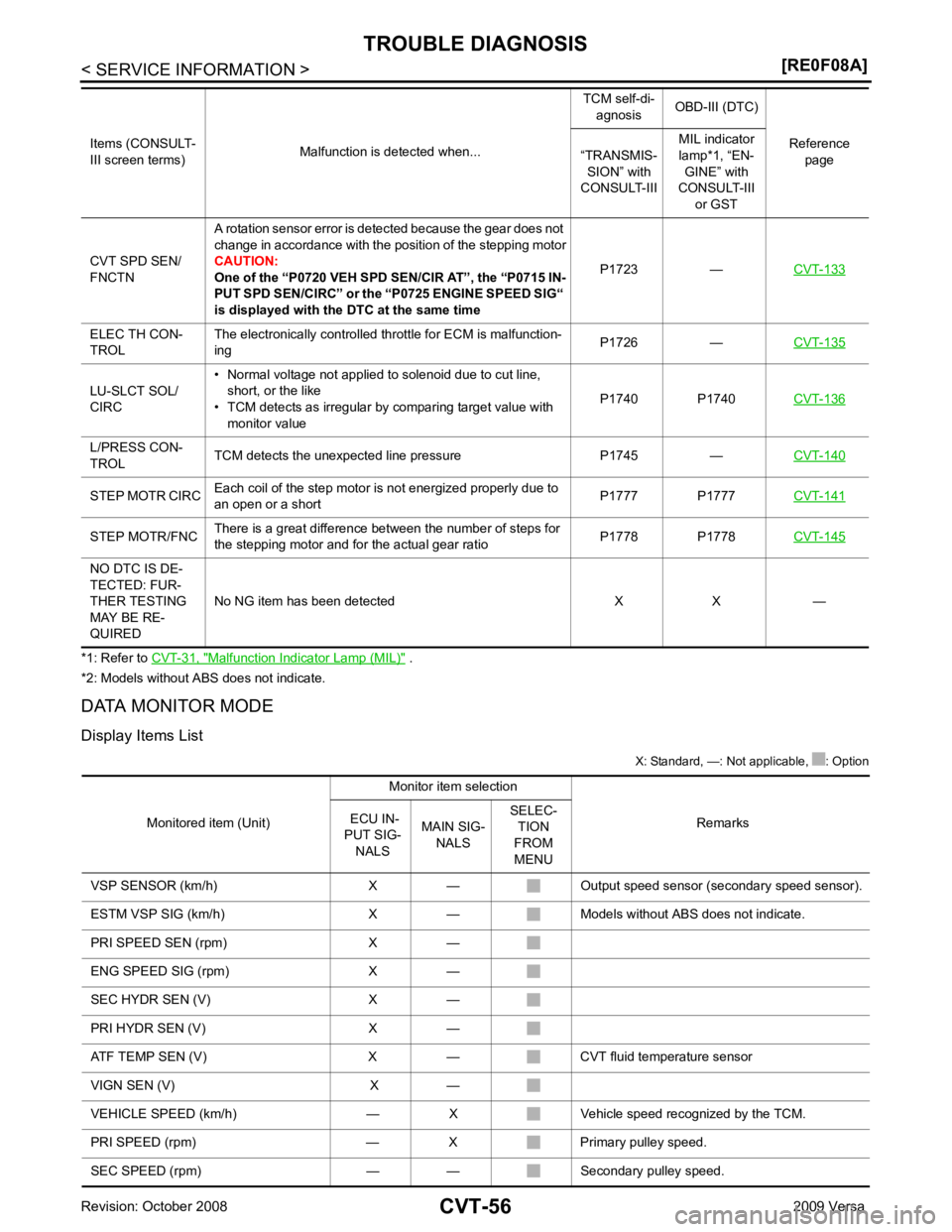
Malfunction Indicator Lamp (MIL) " .
*2: Models without ABS does not indicate.
DATA MONITOR MODE
Display Items List X: Standard, —: Not applicable, : Option
CVT SPD SEN/
FNCTN A rotation sensor error is detected because the gear does not
change in accordance with the position of the stepping motor
CAUTION:
One of the “P0720 VEH SPD SEN/CIR AT”, the “P0715 IN-
PUT SPD SEN/CIRC” or the “P0725 ENGINE SPEED SIG“
is displayed with the DTC at the same time P1723 —
CVT-133ELEC TH CON-
TROL The electronically controlled throttle for ECM is malfunction-
ing P1726 —
CVT-135LU-SLCT SOL/
CIRC • Normal voltage not applied to solenoid due to cut line,
short, or the like
• TCM detects as irregular by comparing target value with
monitor value P1740 P1740
CVT-136L/PRESS CON-
TROL TCM detects the unexpected line pressure P1745 —
CVT-140STEP MOTR CIRC
Each coil of the step motor is not energized properly due to
an open or a short P1777 P1777
CVT-141STEP MOTR/FNC
There is a great difference between the number of steps for
the stepping motor and for the actual gear ratio P1778 P1778
CVT-145NO DTC IS DE-
TECTED: FUR-
THER TESTING
MAY BE RE-
QUIRED No NG item has been detected X X —
Items (CONSULT-
III screen terms) Malfunction is detected when... TCM self-di-
agnosis OBD-III (DTC)
Reference page
“TRANSMIS-
SION” with
CONSULT-III MIL indicator
lamp*1, “EN- GINE” with
CONSULT-III
or GST
Page 1085 of 4331

CVT
N
O P
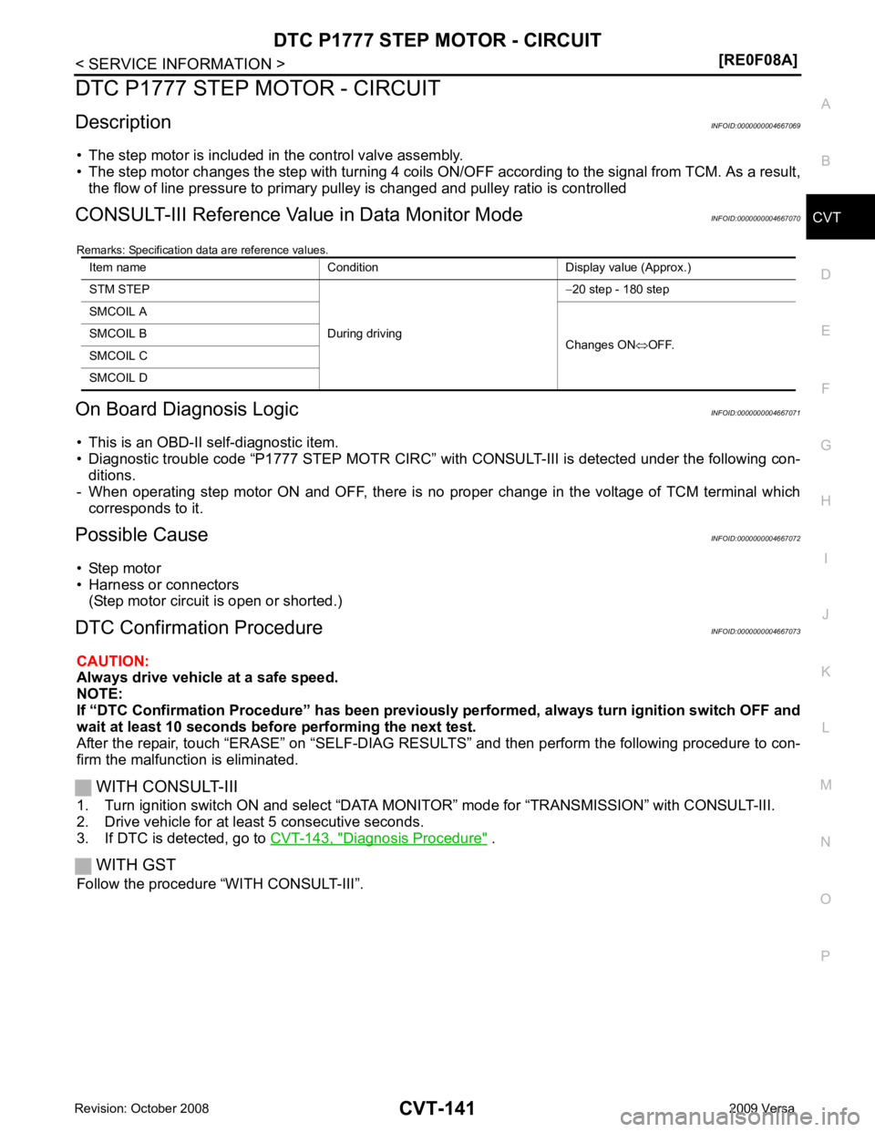
DTC P1777 STEP MOTOR - CIRCUIT
Description INFOID:0000000004667069
• The step motor is included in the control valve assembly.
• The step motor changes the step with turning 4 coils ON/OF F according to the signal from TCM. As a result,
the flow of line pressure to primary pu lley is changed and pulley ratio is controlled
CONSULT-III Reference Val ue in Data Monitor Mode INFOID:0000000004667070
Remarks: Specification data are reference values.
On Board Diagnosis Logic INFOID:0000000004667071
• This is an OBD-II self-diagnostic item.
• Diagnostic trouble code “P1777 STEP MOTR CIRC” with CONSULT-III is detected under the following con-
ditions.
- When operating step motor ON and OFF, there is no proper change in the voltage of TCM terminal which corresponds to it.
Possible Cause INFOID:0000000004667072
• Step motor
• Harness or connectors
(Step motor circuit is open or shorted.)
DTC Confirmation Procedure INFOID:0000000004667073
CAUTION:
Always drive vehicle at a safe speed.
NOTE:
If “DTC Confirmation Procedure” has been previously performed, alw ays turn ignition switch OFF and
wait at least 10 seconds before performing the next test.
After the repair, touch “ERASE” on “SELF-DIAG RESU LTS” and then perform the following procedure to con-
firm the malfunction is eliminated.
WITH CONSULT-III
1. Turn ignition switch ON and select “DATA MO NITOR” mode for “TRANSMISSION” with CONSULT-III.
2. Drive vehicle for at least 5 consecutive seconds.
3. If DTC is detected, go to CVT-143, " Diagnosis Procedure " .
WITH GST
Follow the procedure “WITH CONSULT-III”. Item name Condition Display value (Approx.)
STM STEP
During driving−
20 step - 180 step
SMCOIL A
Changes ON⇔OFF.
SMCOIL B
SMCOIL C
SMCOIL D
Page 1087 of 4331

CVT
N
O P
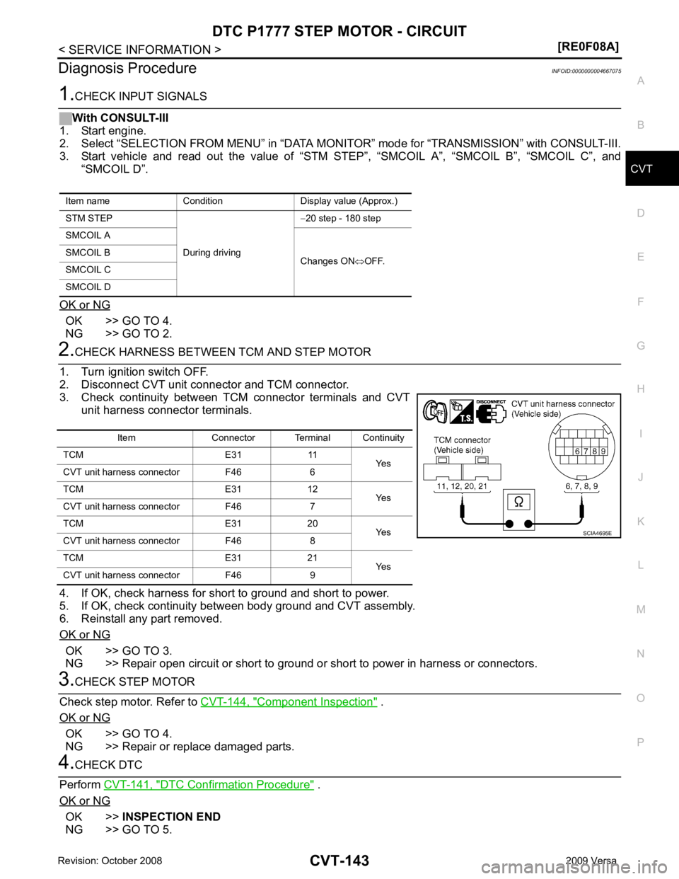
Diagnosis Procedure
INFOID:0000000004667075OK >> GO TO 4.
NG >> GO TO 2. OK >> GO TO 3.
NG >> Repair open circuit or short to ground or short to power in harness or connectors. Component Inspection " .
OK or NG OK >> GO TO 4.
NG >> Repair or replace damaged parts. DTC Confirmation Procedure " .
OK or NG OK >>
INSPECTION END
NG >> GO TO 5.
Item name Condition Display value (Approx.)
STM STEP
During driving−
20 step - 180 step
SMCOIL A
Changes ON⇔OFF.
SMCOIL B
SMCOIL C
SMCOIL D Item Connector Terminal Continuity
TCM E31 11 Yes
CVT unit harness connector F46 6
TCM E31 12 Yes
CVT unit harness connector F46 7
TCM E31 20 Yes
CVT unit harness connector F46 8
TCM E31 21 Yes
CVT unit harness connector F46 9
Page 1149 of 4331
![NISSAN LATIO 2009 Service Repair Manual CVT SYSTEM
CVT-205
< SERVICE INFORMATION >
[RE0F08B] D
E
F
G H
I
J
K L
M A
B CVT
N
O P
*1: Input by CAN communications.
*2: Output by CAN communications.
*3: If these input and output signals are diff NISSAN LATIO 2009 Service Repair Manual CVT SYSTEM
CVT-205
< SERVICE INFORMATION >
[RE0F08B] D
E
F
G H
I
J
K L
M A
B CVT
N
O P
*1: Input by CAN communications.
*2: Output by CAN communications.
*3: If these input and output signals are diff](/manual-img/5/57359/w960_57359-1148.png)
CVT SYSTEM
CVT-205
< SERVICE INFORMATION >
[RE0F08B] D
E
F
G H
I
J
K L
M A
B CVT
N
O P
*1: Input by CAN communications.
*2: Output by CAN communications.
*3: If these input and output signals are different, the TCM triggers the fail-safe function.
Line Pressure and Secondary Pressure Control INFOID:0000000004305579
• When an input torque signal equivalent to the engine drive force is sent from the ECM to the TCM, the TCM
controls the line pressure solenoid valve and secondary pressure solenoid valve.
• This line pressure solenoid controls the pressure regulat or valve as the signal pressure and adjusts the pres-
sure of the operating oil discharged from the oil pump to the line pressure most appropriate to the driving
state. Secondary pressure is cont rolled by decreasing line pressure.
NORMAL CONTROL Optimize the line pressure and secondary pressure, dependi ng on driving conditions, on the basis of the throt-
tle position, the engine speed, the primary pulley (input ) revolution speed, the secondary pulley (output) revo-
lution speed, the brake signal, the PNP switch signal, the lock-up signal, the voltage, the target gear ratio, the
fluid temperature, and the fluid pressure.
FEEDBACK CONTROL When controlling the normal fluid pressure or the sele cted fluid pressure, the secondary pressure can be set
more accurately by using the fluid pressure sensor to detect the secondary pressure and controlling the feed-
back.
Shift Control INFOID:0000000004305580
In order to select the gear ratio which can obtain the dr iving force in accordance with driver's intention and the
vehicle condition, TCM monitors the driving conditions, such as the vehicle speed and the throttle position and
selects the optimum gear ratio, and determines the gear change steps to the gear ratio. Then send the com-
Out-
put Step motor X X
TCC solenoid valve X X X
Lock-up select solenoid valve X X X
Line pressure solenoid valve X X X X
Secondary pressure solenoid valve X X X
O/D OFF indicator signal (*2)
X X
Control item
Fluid
pressure
control Select con-
trol Shift control
Lock-up
control CAN com-
munication
control Fail-safe
function
(*3) SCIA1846E
Page 1156 of 4331

.
Fail-Safe INFOID:0000000004305589
The TCM has an electrical fail-safe mode. This mode make s it possible to operate even if there is an error in a
main electronic control input/output signal circuit.
FAIL-SAFE FUNCTION
If any malfunction occurs in a sensor or solenoid, th is function controls the CVT to make driving possible.
Output Speed Sensor (S econdary Speed Sensor)
The shift pattern is changed in accordance with thrott le position when an unexpected signal is sent from the
output speed sensor (secondary speed sensor) to the TCM. The overdrive-off mode is inhibited, and the tran-
saxle is put in “D”.
Input Speed Sensor (Primary Speed Sensor)
The shift pattern is changed in accordance with thro ttle position and secondary speed (vehicle speed) when
an unexpected signal is sent from the input speed sensor (primary speed sensor) to the TCM. The overdrive-
off mode is inhibited, and the transaxle is put in “D”.
PNP Switch
If an unexpected signal is sent from the PNP switch to the TCM, the transaxle is put in “D”.
CVT Fluid Temperature Sensor
If an unexpected signal is sent from the CVT fluid temper ature sensor to the TCM, the gear ratio in use before
receiving the unexpected signal is maintained or t he gear ratio is controlled to keep engine speed under 3500
rpm.
Transmission Fluid Pressure Sensor A (Secondary Pressure Sensor)
• If an unexpected signal is sent from the transmission fluid pressure sensor A (secondary pressure sensor) to
the TCM, the secondary pressure feedback control is stopped and the offset value obtained before the non-
standard condition occurs is used to control line pressure.
• If transmission fluid pressure sensor A (secondary pres sure sensor) error signal is input to TCM, secondary
pressure feedback control stops, but line pressure is controlled normally.
Pressure Control Solenoid A (Line Pressure Solenoid)
If an unexpected signal is sent from the solenoid to t he TCM, the pressure control solenoid A (line pressure
solenoid) is turned OFF to achieve the maximum fluid pressure.
Pressure Control Solenoid B (Secondary Pressure Solenoid)
If an unexpected signal is sent from the solenoid to t he TCM, the pressure control solenoid B (secondary pres-
sure solenoid) is turned OFF to achieve the maximum fluid pressure.
Torque Converter Clutch Solenoid
If an unexpected signal is sent from the solenoid to t he TCM, the torque converter clutch solenoid is turned
OFF to cancel the lock-up.
Step Motor
If an unexpected signal is sent from the step motor to the TCM, the step motor coil phases “A” through “D” are
all turned OFF to hold the gear ratio used right before the non-standard condition occurred.
CVT Lock-up Select Solenoid Priority Detected items (DTC)
1 U1000 CAN communication line
2 Except above