2009 NISSAN LATIO oil change
[x] Cancel search: oil changePage 1170 of 4331
![NISSAN LATIO 2009 Service Repair Manual CVT-226< SERVICE INFORMATION >
[RE0F08B]
TROUBLE DIAGNOSIS
Cruise Test INFOID:00000000043055971.
CHECK VEHICLE SPEED WHEN SHIFTING GEARS — PART 1
1. Drive vehicle for approximately 10 minutes to wa NISSAN LATIO 2009 Service Repair Manual CVT-226< SERVICE INFORMATION >
[RE0F08B]
TROUBLE DIAGNOSIS
Cruise Test INFOID:00000000043055971.
CHECK VEHICLE SPEED WHEN SHIFTING GEARS — PART 1
1. Drive vehicle for approximately 10 minutes to wa](/manual-img/5/57359/w960_57359-1169.png)
CVT-226< SERVICE INFORMATION >
[RE0F08B]
TROUBLE DIAGNOSIS
Cruise Test INFOID:00000000043055971.
CHECK VEHICLE SPEED WHEN SHIFTING GEARS — PART 1
1. Drive vehicle for approximately 10 minutes to wa rm engine oil and CVT fluid up to operating temperature.
2. Park vehicle on flat surface.
3. Move selector lever to “P” position.
4. Start engine.
5. Move selector lever to “L” position.
6. Accelerate vehicle to 2/8-way throttle depressing accelerator pedal constantly.
Read vehicle speed and engine speed. Refer to CVT- 228, " Vehicle Speed When Shifting Gears " .
OK or NG OK >> GO TO 2.
NG >> Mark the box of CVT-331, " Vehicle Speed Does Not
Change in "L" Position " on the
CVT-213, " How to Per-
form Trouble Diagnosis for Quick and Accurate Repair " .
Continue “Road Test”. 2.
CHECK VEHICLE SPEED WHEN SHIFTING GEARS — PART 2
1. Park vehicle on flat surface.
2. Move selector lever to “D” position.
3. Push overdrive control switch. (O/D OFF indicator lamp is on.)
4. Accelerate vehicle to 2/8-way throttle depressing accelerator pedal constantly.
Read vehicle speed and engine speed. Refer to CVT- 228, " Vehicle Speed When Shifting Gears " .
OK or NG OK >> GO TO 3.
NG >> Mark the box of CVT-332, " Vehicle Speed Does Not
Change in overdrive-off mode " on the
CVT-213, " How
to Perform Trouble Diagnosis for Quick and Accurate
Repair " . Continue “Road Test”.
3.
CHECK VEHICLE SPEED WHEN SHIFTING GEARS — PART 3
1. Park vehicle on flat surface.
2. Move selector lever to “D” position.
3. Push overdrive control switch. (O/D OFF indicator lamp is off.)
4. Accelerate vehicle to 2/8-way throttle depressing accelerator pedal constantly.
Read vehicle speed and engine speed. Refer to CVT- 228, " Vehicle Speed When Shifting Gears " .
OK or NG OK >> GO TO 4.
NG >> Mark the box of CVT-333, " Vehicle Speed Does Not
Change in "D" Position " on the
CVT-213, " How to Per-
form Trouble Diagnosis for Quick and Accurate Repair " .
Continue “Road Test”. 4.
CHECK VEHICLE SPEED WHEN SHIFTING GEARS — PART 4
1. Park vehicle on flat surface.
2. Move selector lever to “L” position. CVT fluid operating temperature: 50 - 80
°C (122 - 176 °F) SCIA6644E
SCIA6644E
SCIA6644E
Page 1178 of 4331

Malfunction Indicator Lamp (MIL) " .
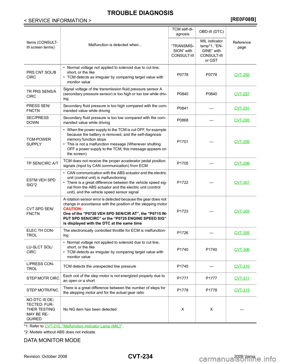
*2: Models without ABS does not indicate.
DATA MONITOR MODE PRS CNT SOL/B
CIRC • Normal voltage not applied to solenoid due to cut line,
short, or the like
• TCM detects as irregular by comparing target value with
monitor value P0778 P0778
CVT-282TR PRS SENS/A
CIRC Signal voltage of the transmission fluid pressure sensor A
(secondary pressure sensor) is too high or too low while driv-
ing P0840 P0840
CVT-287PRESS SEN/
FNCTN Secondary fluid pressure is too high compared with the com-
manded value while driving P0841 —
CVT-291SEC/PRESS
DOWN Secondary fluid pressure is too low compared with the com-
manded value while driving P0868 —
CVT-293TCM-POWER
SUPPLY • When the power supply to the TCM is cut OFF, for example
because the battery is removed, and the self-diagnosis
memory function stops
• This is not a malfunction message (Whenever shutting OFF a power supply to the TCM, this message appears on
the screen) P1701 —
CVT-295TP SEN/CIRC A/T
TCM does not receive the proper accelerator pedal position
signals (input by CAN communication) from ECM P1705 —
CVT-299ESTM VEH SPD
SIG*2 • CAN communication with the
ABS actuator and the electric
unit (control unit) is malfunctioning
• There is a great difference between the vehicle speed sig- nal from the ABS actuator and the electric unit (control
unit), and the vehicle speed sensor signal P1722 —
CVT-301CVT SPD SEN/
FNCTN A rotation sensor error is detected because the gear does not
change in accordance with the position of the stepping motor
CAUTION:
One of the “P0720 VEH SPD SEN/CIR AT”, the “P0715 IN-
PUT SPD SEN/CIRC” or the “P0725 ENGINE SPEED SIG“
is displayed with the DTC at the same time P1723 —
CVT-303ELEC TH CON-
TROL The electronically controlled throttle for ECM is malfunction-
ing P1726 —
CVT-305LU-SLCT SOL/
CIRC • Normal voltage not applied to solenoid due to cut line,
short, or the like
• TCM detects as irregular by comparing target value with monitor value P1740 P1740
CVT-306L/PRESS CON-
TROL TCM detects the unexpected line pressure P1745 —
CVT-310STEP MOTR CIRC
Each coil of the step motor is not energized properly due to
an open or a short P1777 P1777
CVT-311STEP MOTR/FNC
There is a great difference between the number of steps for
the stepping motor and for the actual gear ratio P1778 P1778
CVT-315NO DTC IS DE-
TECTED: FUR-
THER TESTING
MAY BE RE-
QUIRED No NG item has been detected X X —
Items (CONSULT-
III screen terms) Malfunction is detected when... TCM self-di-
agnosis OBD-III (DTC)
Reference page
“TRANSMIS-
SION” with
CONSULT-III MIL indicator
lamp*1, “EN- GINE” with
CONSULT-III
or GST
Page 1255 of 4331

CVT
N
O P
DTC P1777 STEP MOTOR - CIRCUIT
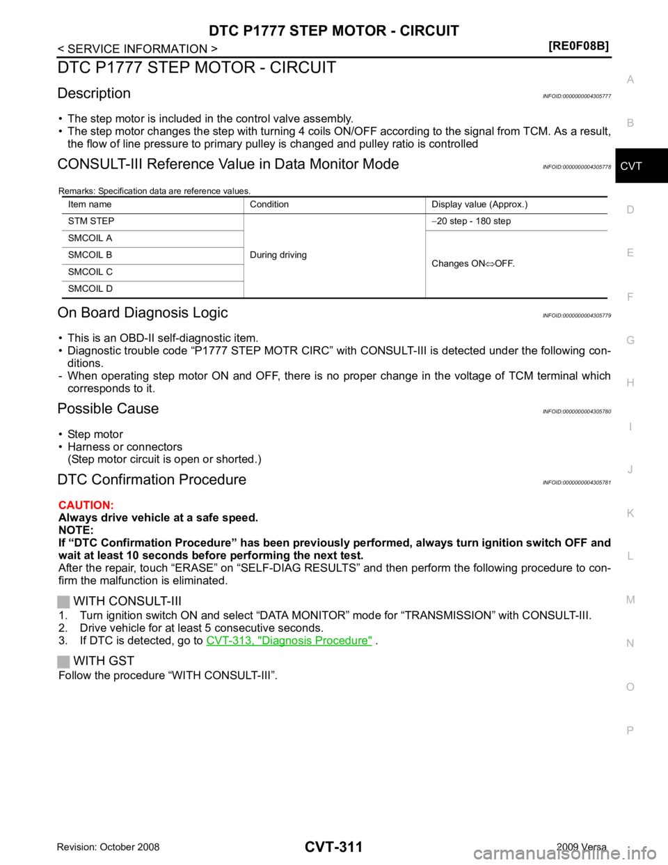
Description INFOID:0000000004305777
• The step motor is included in the control valve assembly.
• The step motor changes the step with turning 4 coils ON/OF F according to the signal from TCM. As a result,
the flow of line pressure to primary pu lley is changed and pulley ratio is controlled
CONSULT-III Reference Val ue in Data Monitor Mode INFOID:0000000004305778
Remarks: Specification data are reference values.
On Board Diagnosis Logic INFOID:0000000004305779
• This is an OBD-II self-diagnostic item.
• Diagnostic trouble code “P1777 STEP MOTR CIRC” with CONSULT-III is detected under the following con-
ditions.
- When operating step motor ON and OFF, there is no proper change in the voltage of TCM terminal which corresponds to it.
Possible Cause INFOID:0000000004305780
• Step motor
• Harness or connectors
(Step motor circuit is open or shorted.)
DTC Confirmation Procedure INFOID:0000000004305781
CAUTION:
Always drive vehicle at a safe speed.
NOTE:
If “DTC Confirmation Procedure” has been previously performed, alw ays turn ignition switch OFF and
wait at least 10 seconds before performing the next test.
After the repair, touch “ERASE” on “SELF-DIAG RESU LTS” and then perform the following procedure to con-
firm the malfunction is eliminated.
WITH CONSULT-III
1. Turn ignition switch ON and select “DATA MO NITOR” mode for “TRANSMISSION” with CONSULT-III.
2. Drive vehicle for at least 5 consecutive seconds.
3. If DTC is detected, go to CVT-313, " Diagnosis Procedure " .
WITH GST
Follow the procedure “WITH CONSULT-III”. Item name Condition Display value (Approx.)
STM STEP
During driving−
20 step - 180 step
SMCOIL A
Changes ON⇔OFF.
SMCOIL B
SMCOIL C
SMCOIL D
Page 1257 of 4331
![NISSAN LATIO 2009 Service Repair Manual DTC P1777 STEP MOTOR - CIRCUIT
CVT-313
< SERVICE INFORMATION >
[RE0F08B] D
E
F
G H
I
J
K L
M A
B CVT
N
O P
Diagnosis Procedure
INFOID:00000000043057831.
CHECK INPUT SIGNALS
With CONSULT-III
1. Start e NISSAN LATIO 2009 Service Repair Manual DTC P1777 STEP MOTOR - CIRCUIT
CVT-313
< SERVICE INFORMATION >
[RE0F08B] D
E
F
G H
I
J
K L
M A
B CVT
N
O P
Diagnosis Procedure
INFOID:00000000043057831.
CHECK INPUT SIGNALS
With CONSULT-III
1. Start e](/manual-img/5/57359/w960_57359-1256.png)
DTC P1777 STEP MOTOR - CIRCUIT
CVT-313
< SERVICE INFORMATION >
[RE0F08B] D
E
F
G H
I
J
K L
M A
B CVT
N
O P
Diagnosis Procedure
INFOID:00000000043057831.
CHECK INPUT SIGNALS
With CONSULT-III
1. Start engine.
2. Select “SELECTION FROM MENU” in “DATA MONI TOR” mode for “TRANSMISSION” with CONSULT-III.
3. Start vehicle and read out the value of “STM STEP”, “SMCOIL A”, “SMCOIL B”, “SMCOIL C”, and
“SMCOIL D”.
OK or NG OK >> GO TO 4.
NG >> GO TO 2. 2.
CHECK HARNESS BETWEEN TCM AND STEP MOTOR
1. Turn ignition switch OFF.
2. Disconnect CVT unit connector and TCM connector.
3. Check continuity between TCM connector terminals and CVT
unit harness connector terminals.
4. If OK, check harness for short to ground and short to power.
5. If OK, check continuity between body ground and CVT assembly.
6. Reinstall any part removed.
OK or NG OK >> GO TO 3.
NG >> Repair open circuit or short to ground or short to power in harness or connectors. 3.
CHECK STEP MOTOR
Check step motor. Refer to CVT-314, " Component Inspection " .
OK or NG OK >> GO TO 4.
NG >> Repair or replace damaged parts. 4.
CHECK DTC
Perform CVT-311, " DTC Confirmation Procedure " .
OK or NG OK >>
INSPECTION END
NG >> GO TO 5.
Item name Condition Display value (Approx.)
STM STEP
During driving−
20 step - 180 step
SMCOIL A
Changes ON⇔OFF.
SMCOIL B
SMCOIL C
SMCOIL D Item Connector Terminal Continuity
TCM E31 11 Yes
CVT unit harness connector F46 6
TCM E31 12 Yes
CVT unit harness connector F46 7
TCM E31 20 Yes
CVT unit harness connector F46 8
TCM E31 21 Yes
CVT unit harness connector F46 9 SCIA4695E
Page 1465 of 4331

EC
NP
O
Test Item
*: Leaving cooling fan OFF with CONSULT-III while engine is running may cause the engine to overheat.
DTC & SRT CONFIRMATION MODE
SRT STATUS Mode For details, refer to EC-90, " Diagnosis Description " .
SRT WORK SUPPORT Mode This mode enables a technician to drive a vehicle to set the SRT while monitoring the SRT status.
DTC WORK SUPPORT Mode TEST ITEM CONDITION JUDGMENT CHECK ITEM (REMEDY)
FUEL INJECTION • Engine: Return to the original
trouble condition
• Change the amount of fuel injec- tion using CONSULT-III. If trouble symptom disappears, see
CHECK ITEM. • Harness and connectors
• Fuel injector
• Air fuel ratio (A/F) sensor 1
IGNITION TIMING • Engine: Return to the original
trouble condition
• Timing light: Set
• Retard the ignition timing using
CONSULT-III. If trouble symptom disappears, see
CHECK ITEM. • Perform Idle Air Volume Learning.
POWER BALANCE • Engine: After warming up, idle
the engine.
• A/C switch OFF
• Selector lever: P or N position (A/ T), Neutral position (M/T)
• Cut off each fuel injector signal
one at a time using CONSULT-
III. Engine runs rough or dies.
• Harness and connectors
• Compression
• Fuel injector
• Power transistor
• Spark plug
• Ignition coil
COOLING FAN* • Ignition switch: ON
• Turn the cooling fan “LOW”, “HI”
and “OFF” using CONSULT-III. Cooling fan moves and stops.
• Harness and connectors
• IPDM E/R (Cooling fan relay)
• Cooling fan motor
ENG COOLANT
TEMP • Engine: Return to the original
trouble condition
• Change the engine coolant tem-
perature using CONSULT-III. If trouble symptom disappears, see
CHECK ITEM. • Harness and connectors
• Engine coolant temperature sen- sor
• Fuel injector
FUEL PUMP RELAY • Ignition switch: ON (Engine
stopped)
• Turn the fuel pump relay “ON”
and “OFF” using CONSULT-III
and listen to operating sound. Fuel pump relay makes the operat-
ing sound. • Harness and connectors
• Fuel pump relay
PURG VOL CONT/V • Engine: After warming up, run
engine at 1,500 rpm.
• Change the EVAP canister purge volume control solenoid
valve opening percent using
CONSULT-III. Engine speed changes according
to the opening percent. • Harness and connectors
• Solenoid valve
FUEL/T TEMP SEN • Change the fuel tank temperature using CONSULT-III.
VENT CONTROL/V • Ignition switch: ON (Engine
stopped)
• Turn solenoid valve “ON” and “OFF” using th e CONSULT-III
and listen to operating sound. Solenoid valve makes an operating
sound. • Harness and connectors
• Solenoid valve
V/T ASSIGN ANGLE • Engine: Return to the original
trouble condition
• Change intake valve timing us-
ing CONSULT-III. If trouble symptom disappears, see
CHECK ITEM. • Harness and connectors
• Intake valve timing control sole- noid valve
Page 1619 of 4331

EC
NP
O
P0335 CKP SENSOR (POS)
Description INFOID:0000000004780158
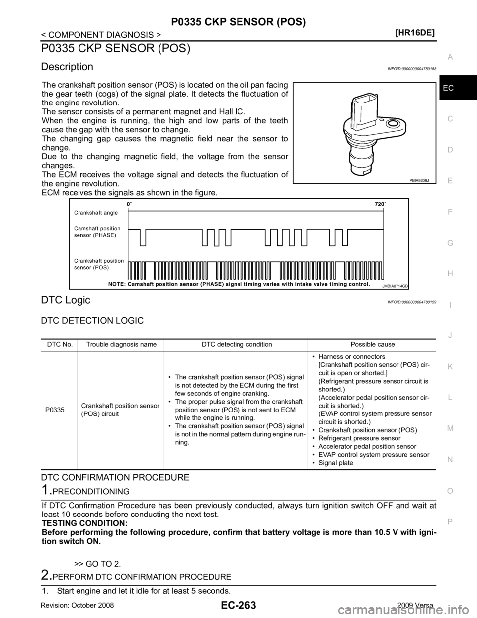
The crankshaft position sensor (POS ) is located on the oil pan facing
the gear teeth (cogs) of the signal pl ate. It detects the fluctuation of
the engine revolution.
The sensor consists of a permanent magnet and Hall IC.
When the engine is running, the high and low parts of the teeth
cause the gap with the sensor to change.
The changing gap causes the magnet ic field near the sensor to
change.
Due to the changing magnetic fiel d, the voltage from the sensor
changes.
The ECM receives the voltage signal and detects the fluctuation of
the engine revolution.
ECM receives the signals as shown in the figure.
DTC Logic INFOID:0000000004780159
DTC DETECTION LOGIC
DTC CONFIRMATION PROCEDURE
Page 1931 of 4331

EC
NP
O
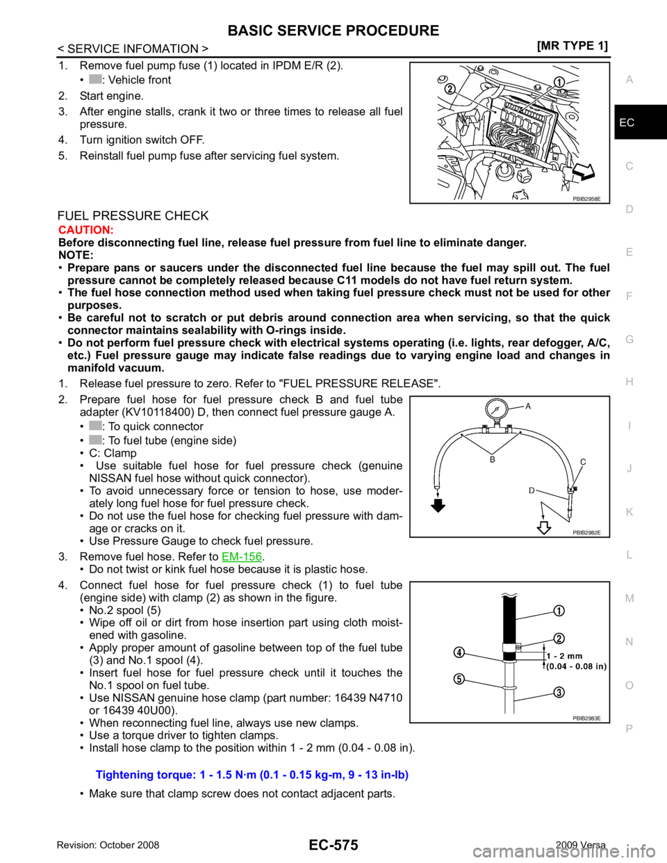
1. Remove fuel pump fuse (1) located in IPDM E/R (2).
• : Vehicle front
2. Start engine.
3. After engine stalls, crank it two or three times to release all fuel pressure.
4. Turn ignition switch OFF.
5. Reinstall fuel pump fuse after servicing fuel system.
FUEL PRESSURE CHECK CAUTION:
Before disconnecting fuel line, release fuel pressure from fuel line to eliminate danger.
NOTE:
• Prepare pans or saucers under the disconnected fuel line because the fuel may spill out. The fuel
pressure cannot be completely released because C11 models do not have fuel return system.
• The fuel hose connection method u sed when taking fuel pressure check must not be used for other
purposes.
• Be careful not to scratch or put debris around connection area when servicing, so that the quick
connector maintains sealability with O-rings inside.
• Do not perform fuel pressure check with electrical syst ems operating (i.e. lights, rear defogger, A/C,
etc.) Fuel pressure gauge may indicate false readin gs due to varying engine load and changes in
manifold vacuum.
1. Release fuel pressure to zero. Refer to "FUEL PRESSURE RELEASE".
2. Prepare fuel hose for fuel pressure check B and fuel tube adapter (KV10118400) D, then connect fuel pressure gauge A.
• : To quick connector
• : To fuel tube (engine side)
• C: Clamp
• Use suitable fuel hose for fuel pressure check (genuine
NISSAN fuel hose without quick connector).
• To avoid unnecessary force or tension to hose, use moder- ately long fuel hose for fuel pressure check.
• Do not use the fuel hose for checking fuel pressure with dam- age or cracks on it.
• Use Pressure Gauge to check fuel pressure.
3. Remove fuel hose. Refer to EM-156 .
• Do not twist or kink fuel hose because it is plastic hose.
4. Connect fuel hose for fuel pressure check (1) to fuel tube (engine side) with clamp (2) as shown in the figure.
• No.2 spool (5)
• Wipe off oil or dirt from hose insertion part using cloth moist-
ened with gasoline.
• Apply proper amount of gasoline between top of the fuel tube (3) and No.1 spool (4).
• Insert fuel hose for fuel pressure check until it touches the No.1 spool on fuel tube.
• Use NISSAN genuine hose clamp (part number: 16439 N4710
or 16439 40U00).
• When reconnecting fuel line, always use new clamps.
• Use a torque driver to tighten clamps.
• Install hose clamp to the positi on within 1 - 2 mm (0.04 - 0.08 in).
• Make sure that clamp screw does not contact adjacent parts.
Page 1967 of 4331
![NISSAN LATIO 2009 Service Repair Manual EC
NP
O
NOTE:
Any monitored item that does not match the vehicle being diagnosed is deleted from the display automatically.
ACTIVE TEST MODE
Test Item AT OD CANCEL
[ON/OFF] • Indicates [ON/OFF] cond NISSAN LATIO 2009 Service Repair Manual EC
NP
O
NOTE:
Any monitored item that does not match the vehicle being diagnosed is deleted from the display automatically.
ACTIVE TEST MODE
Test Item AT OD CANCEL
[ON/OFF] • Indicates [ON/OFF] cond](/manual-img/5/57359/w960_57359-1966.png)
EC
NP
O
NOTE:
Any monitored item that does not match the vehicle being diagnosed is deleted from the display automatically.
ACTIVE TEST MODE
Test Item AT OD CANCEL
[ON/OFF] • Indicates [ON/OFF] condition of A/T O/D cancel signal sent
from the TCM. • For M/T models always “OFF” is displayed
CRUISE LAMP
[ON/OFF] • Indicates [ON/OFF]
condition of CRUISE lamp determined
by the ECM according to the input signals.
SET LAMP
[ON/OFF] • Indicates [ON/OFF] condition of SET lamp determined by the
ECM according to the input signals.
A/F ADJ-B1 • Indicates the correction factor stored in ECM. The factor is
calculated from the difference between the target air/fuel ratio
stored in ECM and the air/fuel ratio calculated from air fuel ra-
tio (A/F) sensor 1 signal.
Monitored item [Unit] Description Remarks TEST ITEM CONDITION JUDGEMENT CHECK ITEM (REMEDY)
FUEL INJEC-
TION • Engine: Return to the original
trouble condition
• Change the amount of fuel injec- tion using CONSULT-III. If trouble symptom disappears, see
CHECK ITEM. • Harness and connectors
• Fuel injector
• Air fuel ratio (A/F) sensor 1
IGNITION TIM-
ING • Engine: Return to the original
trouble condition
• Timing light: Set
• Retard the ignition timing using
CONSULT-III. If trouble symptom disappears, see
CHECK ITEM. • Perform Idle Air Volume Learning.
POWER BAL-
ANCE • Engine: After warming up, idle the
engine.
• A/C switch OFF
• Shift lever: P or N (A/T, CVT), Neutral (M/T)
• Cut off each fuel injector signal
one at a time using CONSULT-III. Engine runs rough or dies.
• Harness and connectors
• Compression
• Fuel injector
• Power transistor
• Spark plug
• Ignition coil
COOLING FAN* • Ignition switch: ON
• Turn the cooling fan “LOW”, “HI” and “OFF” with CONSULT-III. Cooling fan moves and stops. • Harness and connectors
• Cooling fan relay
• Cooling fan motor
ENG COOLANT
TEMP • Engine: Return to the original
trouble condition
• Change the engine coolant tem- perature using CONSULT-III. If trouble symptom disappears, see
CHECK ITEM. • Harness and connectors
• Engine coolant temperature sen-
sor
• Fuel injector
FUEL PUMP RE-
LAY • Ignition switch: ON
(Engine stopped)
• Turn the fuel pump relay ON and OFF using CONSULT-III and lis-
ten to operating sound. Fuel pump relay makes the operat-
ing sound. • Harness and connectors
• Fuel pump relay
PURG VOL
CONT/V • Engine: After warming up, run en-
gine at 1,500 rpm.
• Change the EVAP canister purge volume control solenoid valve
opening percent using CON-
SULT-III. Engine speed changes according to
the opening percent. • Harness and connectors
• EVAP canister purge volume con- trol solenoid valve
FUEL/T TEMP
SEN • Change the fuel tank temperature using CONSULT-III.