2009 NISSAN LATIO washer fluid
[x] Cancel search: washer fluidPage 1298 of 4331
![NISSAN LATIO 2009 Service Repair Manual CVT-354< SERVICE INFORMATION >
[RE0F08B]
TRANSAXLE ASSEMBLY
TRANSAXLE ASSEMBLY
Removal and Installation INFOID:0000000004305824
COMPONENTS
REMOVAL
1. Remove the engine and transaxle as an assembly. Re NISSAN LATIO 2009 Service Repair Manual CVT-354< SERVICE INFORMATION >
[RE0F08B]
TRANSAXLE ASSEMBLY
TRANSAXLE ASSEMBLY
Removal and Installation INFOID:0000000004305824
COMPONENTS
REMOVAL
1. Remove the engine and transaxle as an assembly. Re](/manual-img/5/57359/w960_57359-1297.png)
CVT-354< SERVICE INFORMATION >
[RE0F08B]
TRANSAXLE ASSEMBLY
TRANSAXLE ASSEMBLY
Removal and Installation INFOID:0000000004305824
COMPONENTS
REMOVAL
1. Remove the engine and transaxle as an assembly. Refer to EM-195, " Removal and Installation " .
2. Disconnect the primary speed sensor (A) and the secondary speed sensor connector (B) and CVT unit connector (C). Refer
to CVT-191, " Removal and Installation Procedure for CVT Unit
Connector " .
3. Remove the harness from the transaxle. 1. CVT fluid level gauge 2. CVT fluid charging pipe 3. O-ring
4. Copper washer 5. Fluid cooler tube 6. Transaxle assembly
7. Engine mounting bracket (LH) 8. Air breather hose A. Refer to "INSTALLATION". WCIA0614E
AWDIA0661G B
Page 1299 of 4331
![NISSAN LATIO 2009 Service Repair Manual TRANSAXLE ASSEMBLY
CVT-355
< SERVICE INFORMATION >
[RE0F08B] D
E
F
G H
I
J
K L
M A
B CVT
N
O P
4. Remove the four drive plate to torque converter nuts.
NOTE:
Rotate the crankshaft clockwise as vi NISSAN LATIO 2009 Service Repair Manual TRANSAXLE ASSEMBLY
CVT-355
< SERVICE INFORMATION >
[RE0F08B] D
E
F
G H
I
J
K L
M A
B CVT
N
O P
4. Remove the four drive plate to torque converter nuts.
NOTE:
Rotate the crankshaft clockwise as vi](/manual-img/5/57359/w960_57359-1298.png)
TRANSAXLE ASSEMBLY
CVT-355
< SERVICE INFORMATION >
[RE0F08B] D
E
F
G H
I
J
K L
M A
B CVT
N
O P
4. Remove the four drive plate to torque converter nuts.
NOTE:
Rotate the crankshaft clockwise as viewed from front of engine
for access to drive plate to torque converter nuts.
5. Put matching marks on the drive plate and torque converter alignment stud. CAUTION:
For matching marks, use paint. Never dama ge the drive plate or torque converter.
6. Remove the transaxle to engine and engine to transaxle bolts.
7. Separate the transaxle from the engine.
8. If necessary, remove the following from the transaxle: • CVT fluid charging pipe
• Engine mounting bracket (LH)
• Fluid cooler tubes
• Air breather hose
• Any necessary brackets
INSTALLATION Installation is in the reverse order of removal.
CAUTION:
• When replacing an engine or transmission you mu st make sure any dowels are installed correctly
during re-assembly.
• Improper alignment caused by missing dowels m ay cause vibration, oil leaks or breakage of drive
train components.
• Do not reuse O-rings and copper washers.
• When turning crankshaft, turn it clockwise as viewed from the front of the engine.
• When tightening the nuts for the torque converter while securing the crankshaft pulley bolt, be sure
to confirm the tightening torque of the crankshaft pulley bolt. Refer to EM-160 .
• After converter is installed to drive plate, ro tate crankshaft several turns to check that transaxle
rotates freely without binding.
• When installing the torque converter to the transaxle measure dis- tance A. WCIA0616E
Distance A: 14.4 mm (0.57 in) or more
WCIA0617E
Page 1312 of 4331
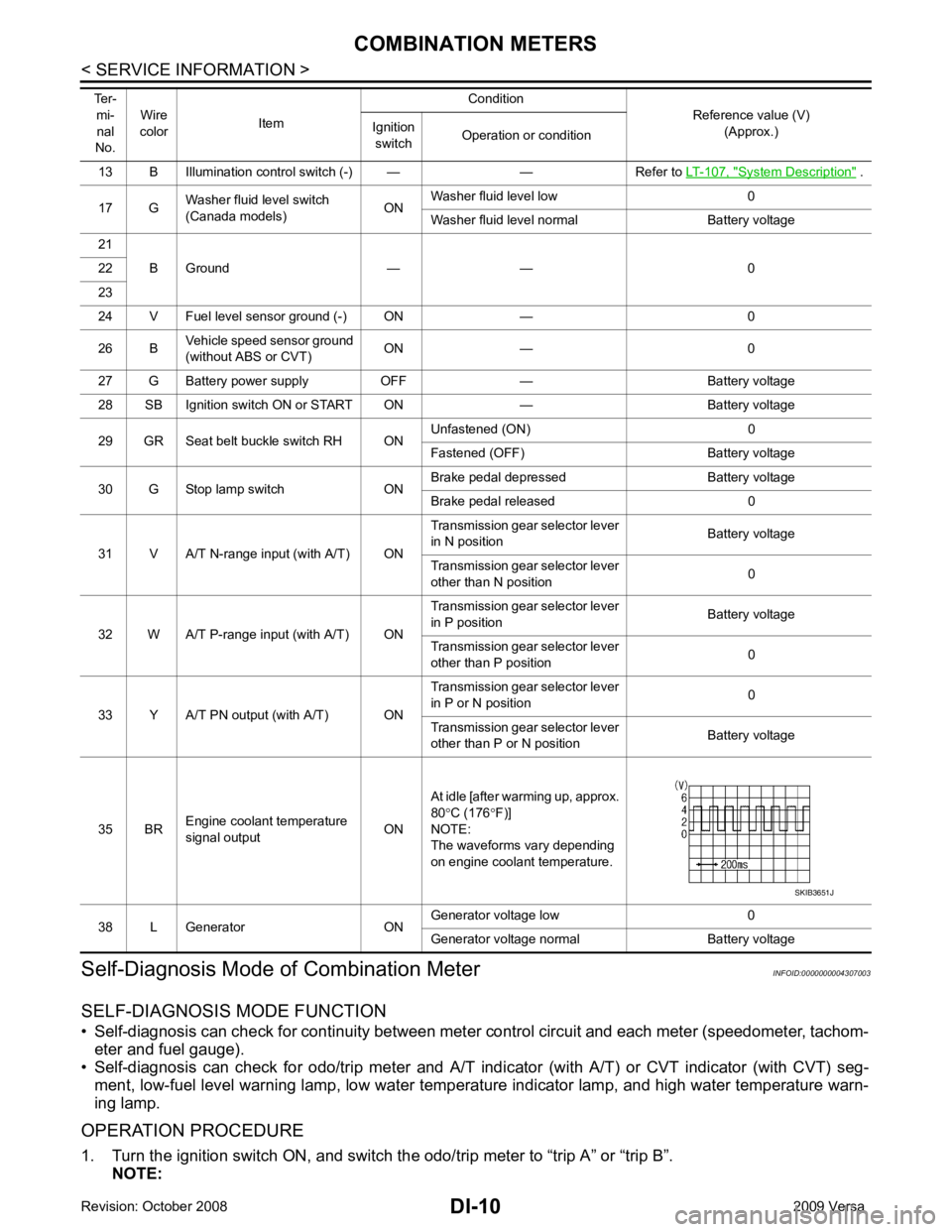
System Description " .
17 G Washer fluid level switch
(Canada models) ONWasher fluid level low 0
Washer fluid level normal Battery voltage
21 B Ground — — 0
22
23
24 V Fuel level sensor ground (-) ON — 0
26 B Vehicle speed sensor ground
(without ABS or CVT) ON — 0
27 G Battery power supply OFF — Battery voltage
28 SB Ignition switch ON or START ON — Battery voltage
29 GR Seat belt buckle switch RH ON Unfastened (ON) 0
Fastened (OFF) Battery voltage
30 G Stop lamp switch ON Brake pedal depressed Battery voltage
Brake pedal released 0
31 V A/T N-range input (with A/T) ON Transmission gear selector lever
in N position Battery voltage
Transmission gear selector lever
other than N position 0
32 W A/T P-range input (with A/T) ON Transmission gear selector lever
in P position Battery voltage
Transmission gear selector lever
other than P position 0
33 Y A/T PN output (with A/T) ON Transmission gear selector lever
in P or N position 0
Transmission gear selector lever
other than P or N position Battery voltage
35 BR Engine coolant temperature
signal output ONAt idle [after warming up, approx.
80 °C (176 °F)]
NOTE:
The waveforms vary depending
on engine coolant temperature.
38 L Generator ON Generator voltage low 0
Generator voltage normal Battery voltage
Ter-
mi-
nal
No. Wire
color Item Condition
Reference value (V)
(Approx.)
Ignition
switch Operation or condition
Page 3145 of 4331
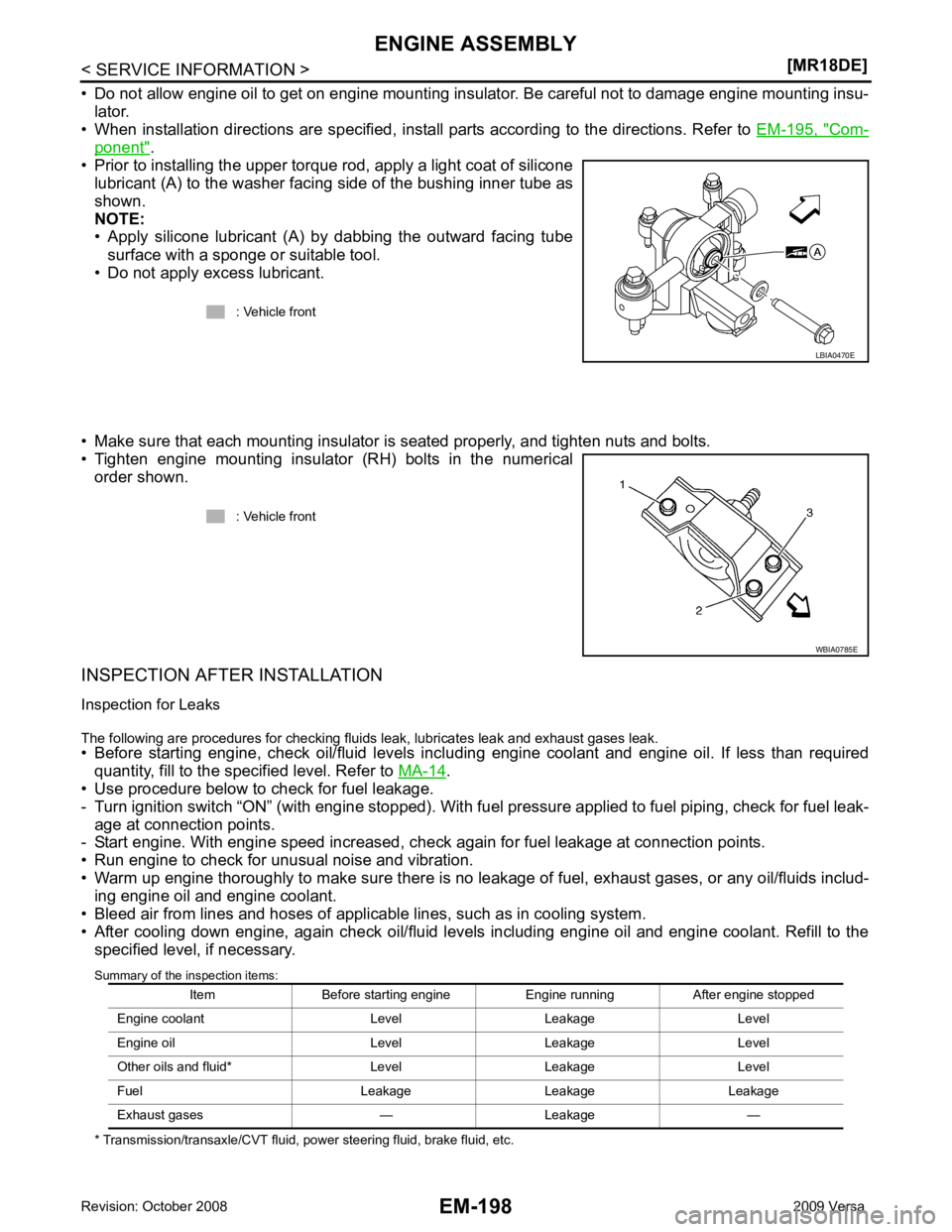
Com-
ponent " .
• Prior to installing the upper torque rod, apply a light coat of silicone lubricant (A) to the washer facing side of the bushing inner tube as
shown.
NOTE:
• Apply silicone lubricant (A) by dabbing the outward facing tube
surface with a sponge or suitable tool.
• Do not apply excess lubricant.
• Make sure that each mounting insulator is seated properly, and tighten nuts and bolts.
• Tighten engine mounting insulator (RH) bolts in the numerical order shown.
INSPECTION AFTER INSTALLATION
Inspection for Leaks
The following are procedures for checking fluids leak, lubricates leak and exhaust gases leak.
• Before starting engine, check oil/fluid levels incl uding engine coolant and engine oil. If less than required
quantity, fill to the specified level. Refer to MA-14 .
• Use procedure below to check for fuel leakage.
- Turn ignition switch “ON” (with engine stopped). With fuel pressure applied to fuel piping, check for fuel leak-
age at connection points.
- Start engine. With engine speed increased, che ck again for fuel leakage at connection points.
• Run engine to check for unusual noise and vibration.
• Warm up engine thoroughly to make sure there is no leak age of fuel, exhaust gases, or any oil/fluids includ-
ing engine oil and engine coolant.
• Bleed air from lines and hoses of applicable lines, such as in cooling system.
• After cooling down engine, again check oil/fluid levels including engine oil and engine coolant. Refill to the specified level, if necessary.
Summary of the inspection items:
* Transmission/transaxle/CVT fluid, power steering fluid, brake fluid, etc. : Vehicle front
Page 3262 of 4331
GI
N
O P
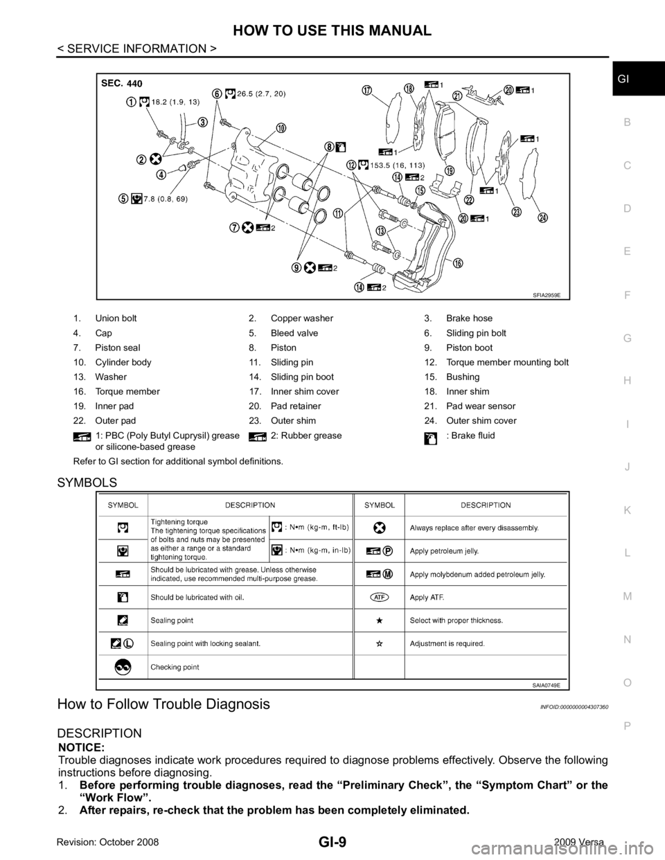
SYMBOLS
How to Follow Trouble Diagnosis INFOID:0000000004307360
DESCRIPTION NOTICE:
Trouble diagnoses indicate work procedures required to diagnose problems effectively. Observe the following
instructions before diagnosing.
1. Before performing trouble diagno ses, read the “Preliminary Check” , the “Symptom Chart” or the
“Work Flow”.
2. After repairs, re-check that the prob lem has been completely eliminated.
1. Union bolt 2. Copper washer 3. Brake hose
4. Cap 5. Bleed valve 6. Sliding pin bolt
7. Piston seal 8. Piston 9. Piston boot
10. Cylinder body 11. Sliding pin 12. Torque member mounting bolt
13. Washer 14. Sliding pin boot 15. Bushing
16. Torque member 17. Inner shim cover 18. Inner shim
19. Inner pad 20. Pad retainer 21. Pad wear sensor
22. Outer pad 23. Outer shim 24. Outer shim cover 1: PBC (Poly Butyl Cuprysil) grease
or silicone-based grease 2: Rubber grease : Brake fluid
Refer to GI section for additional symbol definitions.
Page 3729 of 4331
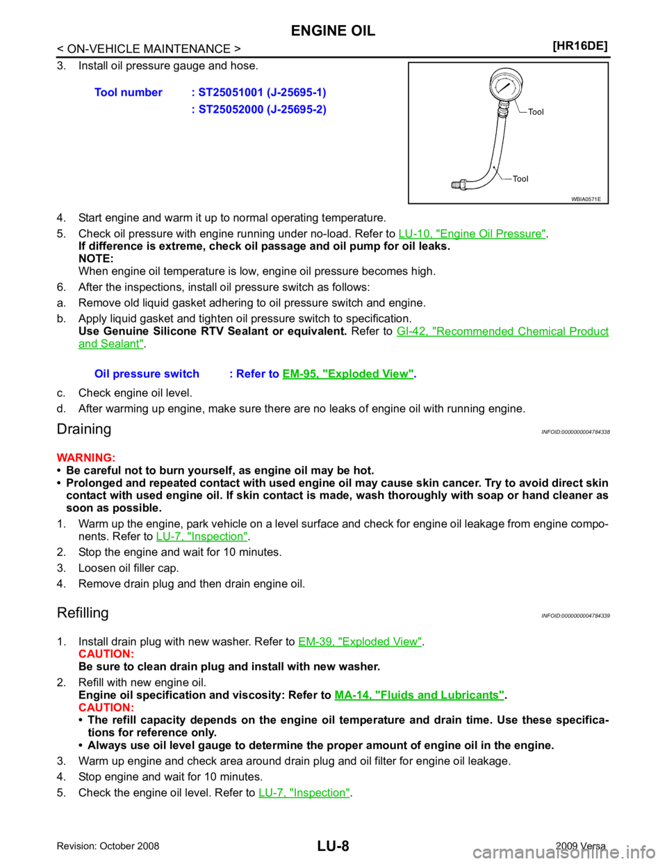
Engine Oil Pressure " .
If difference is extreme, check oil passage and oil pump for oil leaks.
NOTE:
When engine oil temperature is low, engine oil pressure becomes high.
6. After the inspections, install oil pressure switch as follows:
a. Remove old liquid gasket adhering to oil pressure switch and engine.
b. Apply liquid gasket and tighten oil pressure switch to specification. Use Genuine Silicone RTV Sealant or equivalent. Refer to GI-42, " Recommended Chemical Product
and Sealant " .
c. Check engine oil level.
d. After warming up engine, make sure there are no leaks of engine oil with running engine.
Draining INFOID:0000000004784338
WARNING:
• Be careful not to burn yoursel f, as engine oil may be hot.
• Prolonged and repeated contact with used engine oil may cause ski n cancer. Try to avoid direct skin
contact with used engine oil. If skin contact is made, wash thoroughly with soap or hand cleaner as
soon as possible.
1. Warm up the engine, park vehicle on a level surface and check for engine oil leakage from engine compo- nents. Refer to LU-7, " Inspection " .
2. Stop the engine and wait for 10 minutes.
3. Loosen oil filler cap.
4. Remove drain plug and then drain engine oil.
Refilling INFOID:0000000004784339
1. Install drain plug with new washer. Refer to EM-39, " Exploded View " .
CAUTION:
Be sure to clean drain plug and install with new washer.
2. Refill with new engine oil. Engine oil specification and viscosity: Refer to MA-14, " Fluids and Lubricants " .
CAUTION:
• The refill capacity depends on the engine oi l temperature and drain time. Use these specifica-
tions for reference only.
• Always use oil level gauge to determine the pr oper amount of engine oil in the engine.
3. Warm up engine and check area around drain plug and oil filter for engine oil leakage.
4. Stop engine and wait for 10 minutes.
5. Check the engine oil level. Refer to LU-7, " Inspection " .
Tool number : ST25051001 (J-25695-1)
: ST25052000 (J-25695-2) Exploded View " .
Page 3765 of 4331
MA-22< SERVICE INFORMATION >
ENGINE MAINTENANCE (HR16DE)
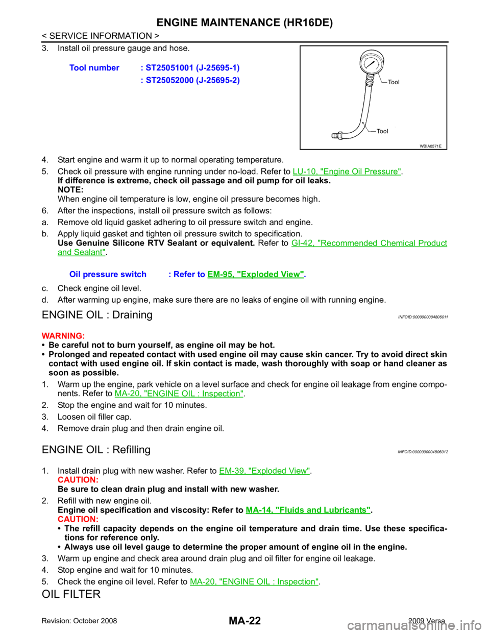
3. Install oil pressure gauge and hose.
4. Start engine and warm it up to normal operating temperature.
5. Check oil pressure with engine running under no-load. Refer to LU-10, " Engine Oil Pressure " .
If difference is extreme, check oil passage and oil pump for oil leaks.
NOTE:
When engine oil temperature is low, engine oil pressure becomes high.
6. After the inspections, install oil pressure switch as follows:
a. Remove old liquid gasket adhering to oil pressure switch and engine.
b. Apply liquid gasket and tighten oil pressure switch to specification. Use Genuine Silicone RTV Sealant or equivalent. Refer to GI-42, " Recommended Chemical Product
and Sealant " .
c. Check engine oil level.
d. After warming up engine, make sure there are no leaks of engine oil with running engine.
ENGINE OIL : Draining INFOID:0000000004806011
WARNING:
• Be careful not to burn yoursel f, as engine oil may be hot.
• Prolonged and repeated contact with used engine oil may cause ski n cancer. Try to avoid direct skin
contact with used engine oil. If skin contact is made, wash thoroughly with soap or hand cleaner as
soon as possible.
1. Warm up the engine, park vehicle on a level surface and check for engine oil leakage from engine compo- nents. Refer to MA-20, " ENGINE OIL : Inspection " .
2. Stop the engine and wait for 10 minutes.
3. Loosen oil filler cap.
4. Remove drain plug and then drain engine oil.
ENGINE OIL : Refilling INFOID:0000000004806012
1. Install drain plug with new washer. Refer to EM-39, " Exploded View " .
CAUTION:
Be sure to clean drain plug and install with new washer.
2. Refill with new engine oil. Engine oil specification and viscosity: Refer to MA-14, " Fluids and Lubricants " .
CAUTION:
• The refill capacity depends on the engine oi l temperature and drain time. Use these specifica-
tions for reference only.
• Always use oil level gauge to determine the pr oper amount of engine oil in the engine.
3. Warm up engine and check area around drain plug and oil filter for engine oil leakage.
4. Stop engine and wait for 10 minutes.
5. Check the engine oil level. Refer to MA-20, " ENGINE OIL : Inspection " .
OIL FILTER Tool number : ST25051001 (J-25695-1)
: ST25052000 (J-25695-2) WBIA0571E
Oil pressure switch : Refer to
EM-95, " Exploded View " .
Page 3810 of 4331
Removal and Installa-
tion " .
REMOVAL
1. Drain gear oil. Refer to MT-10, " Draining " (RS5F91R),
MT-52, " Changing M/T Oil " (RS6F94R).
2. Drain clutch fluid and remove clutch tube from CSC. Refer to CL-12, " Removal and Installation " .
CAUTION:
Do not depress clutch pedal during removal procedure.
3. Remove the engine and transaxle as an assembly from the vehicle. Refer to EM-88, " Removal and Instal-
lation " (HR16DE),
EM-195, " Removal and Installation " (MR18DE).
4. Remove the transaxle to engine and engine to transaxle bolts.
5. Separate the transaxle assembly from the engine.
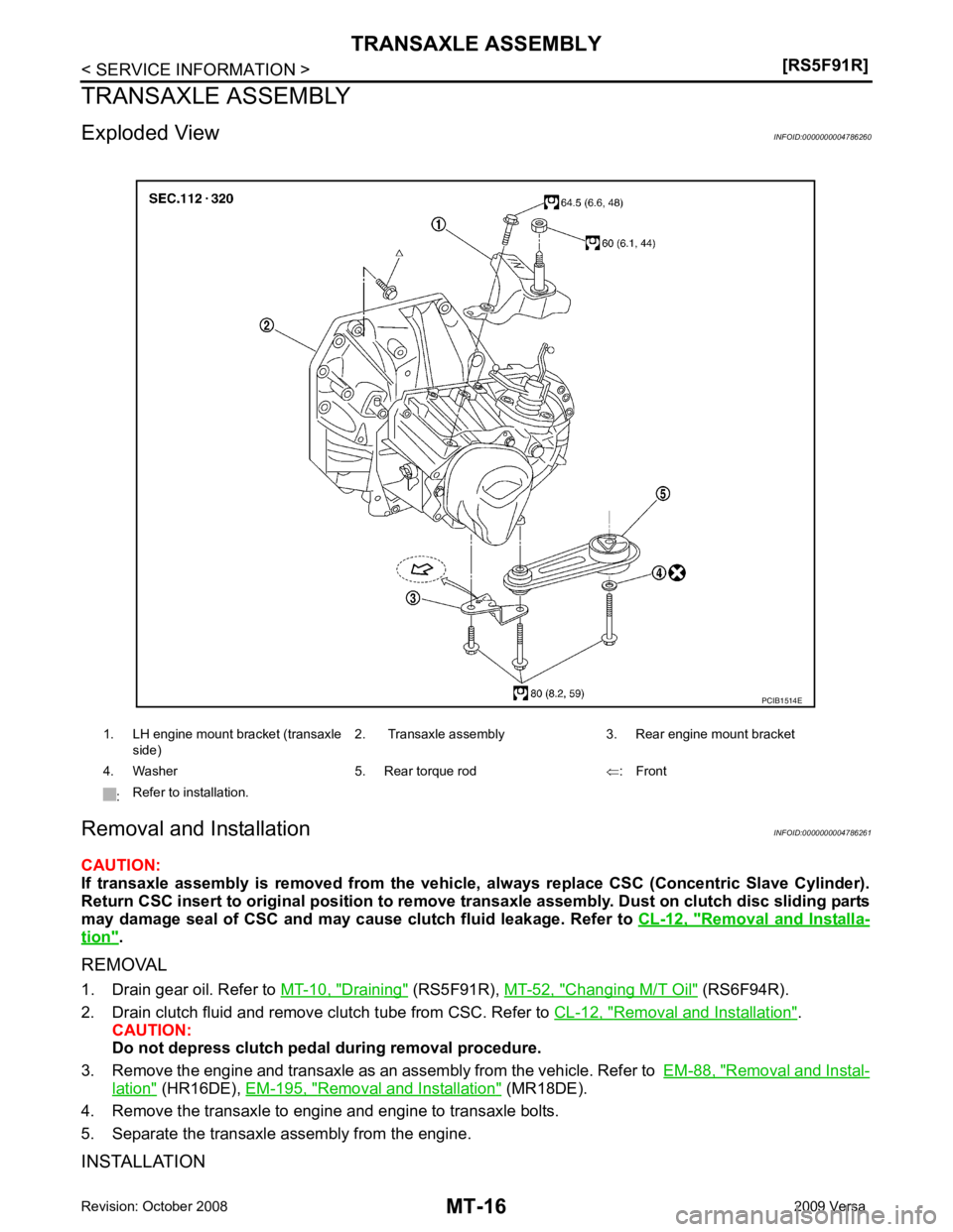
INSTALLATION 1. LH engine mount bracket (transaxle
side) 2. Transaxle assembly 3. Rear engine mount bracket
4. Washer 5. Rear torque rod ⇐: Front
: Refer to installation.