2009 NISSAN LATIO washer fluid
[x] Cancel search: washer fluidPage 14 of 4331
AT
N
O P
• The valve body contains precision parts and requires extreme care when parts are removed and serviced.
Place disassembled valve body parts in order for easier and proper assembly. Care will also prevent springs
and small parts from becoming scattered or lost.
• Properly installed valves, sleeves, plugs, etc. will slide along bores in valve body under their own weight.
• Before assembly, apply a coat of recommended ATF to all parts. Apply petroleum jelly to protect O-rings and
seals, or hold bearings and washers in pl ace during assembly. Do not use grease.
• Extreme care should be taken to avoid damage to O-rings, seals and gaskets when assembling.
• Clean or replace ATF cooler if excessive foreign material is found in oil pan or clogging strainer. Refer to AT-18, " A/T Fluid Cooler Cleaning " .
• After overhaul, refill the A/T with new ATF.
• When the A/T drain plug is removed, only some of the fluid is drained. Old A/T fluid will remain in torque con- verter and ATF cooling system.
Always follow the procedures under “Changing A/T Fluid” in the AT section when changing A/T fluid. Refer to
AT-17, " Changing A/T Fluid " ,
AT-17, " Checking A/T Fluid " .
Service Notice or Precaution INFOID:0000000004305292
ATF COOLER SERVICE If A/T fluid contains frictional material (clutches, bands, etc.), or if an A/T is repaired, overhauled, or replaced,
inspect and clean the A/T oil cooler mounted in the radiator or replace the radiator. Flush cooler lines using
cleaning solvent and compressed air after repair. Check Serv ice Bulletins for latest A/T oil cooler cleaning pro-
cedure. For radiator replacement, refer to CO-16, " Removal and Installation " (HR16DE engine models),
CO-38, " Removal and Installation " (MR18DE engine models).
TORQUE CONVERTER SERVICE The torque converter should be replaced under any of the following conditions:
• External leaks in the hub weld area.
• Converter hub is scored or damaged.
• Converter pilot is broken, damaged or fits poorly into crankshaft.
• Steel particles are found after flushing the cooler and cooler lines.
• Pump is damaged or steel particles are found in the converter.
• Vehicle has TCC shudder and/or no TCC apply. Replace only after all hydraulic and electrical diagnoses
have been made. (Converter clutch material may be glazed.)
• Converter is contaminated with engi ne coolant containing antifreeze.
• Internal malfunction of stator roller clutch.
• Heavy clutch debris due to overheating (blue converter).
• Steel particles or clutch lining material found in flui d filter or on magnet when no internal parts in unit are
worn or damaged — indicates that lining material came from converter.
The torque converter should not be replaced if:
• The fluid has an odor, is discolored, and there is no evidence of metal or clutch facing particles.
• The threads in one or more of the converter bolt holes are damaged.
• A/T malfunction did not display evidence of damaged or worn internal parts, steel particles or clutch plate lin-
ing material in unit and inside the fluid filter.
• Vehicle has been exposed to high mileage (only). The e xception may be where the torque converter clutch
dampener plate lining has seen excess wear by vehicles operated in heavy and/or constant traffic, such as
taxi, delivery or police use.
OBD-II SELF-DIAGNOSIS • A/T self-diagnosis is performed by the TCM in combination with the ECM. The results can be read through the blinking pattern of the OD OFF indicator lamp or the malfunction indicator lamp (MIL). Refer to the table
on AT-83, " Diagnosis Procedure without CONSULT-III " for the indicator used to display each self-diagnostic
result.
• The self-diagnostic results indicated by the MIL ar e automatically stored in both the ECM and TCM memo-
ries.
Always perform the procedure “HOW TO ERASE DTC” on AT-39, " OBD-II Diagnostic Trouble Code
(DTC) " to complete the repair and avo
id unnecessary blinking of the MIL.
• The following self-diagnostic items can be detected us ing ECM self-diagnostic results mode* only when the
OD OFF indicator lamp does not indicate any malfunctions.
- PNP switch
- A/T 1st, 2nd, 3rd, or 4th gear function
*: For details of OBD-II, refer to AT-39 .
Page 237 of 4331
Removal and Installation " .
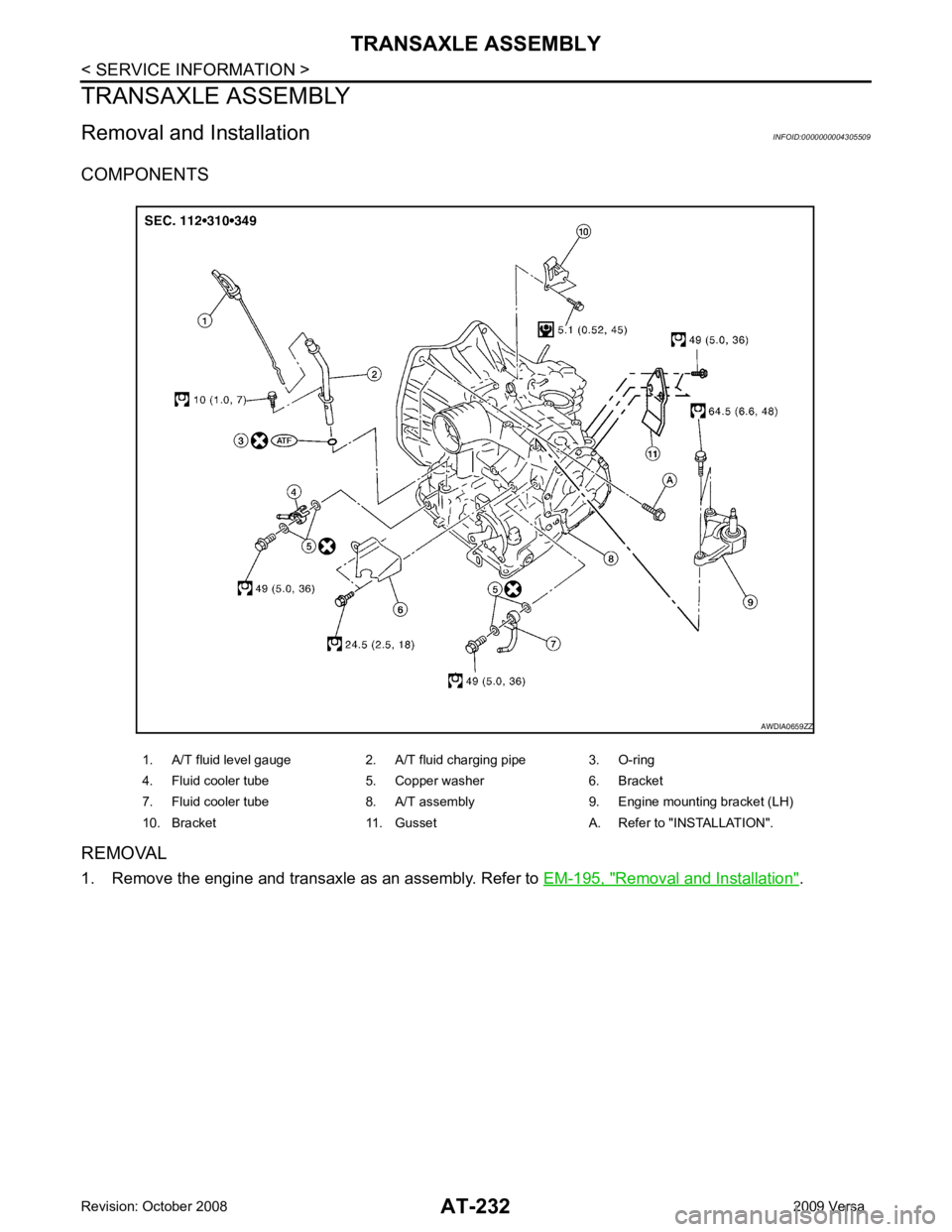
1. A/T fluid level gauge 2. A/T fluid charging pipe 3. O-ring
4. Fluid cooler tube 5. Copper washer 6. Bracket
7. Fluid cooler tube 8. A/T assembly 9. Engine mounting bracket (LH)
10. Bracket 11. Gusset A. Refer to "INSTALLATION".
Page 238 of 4331
AT
N
O P
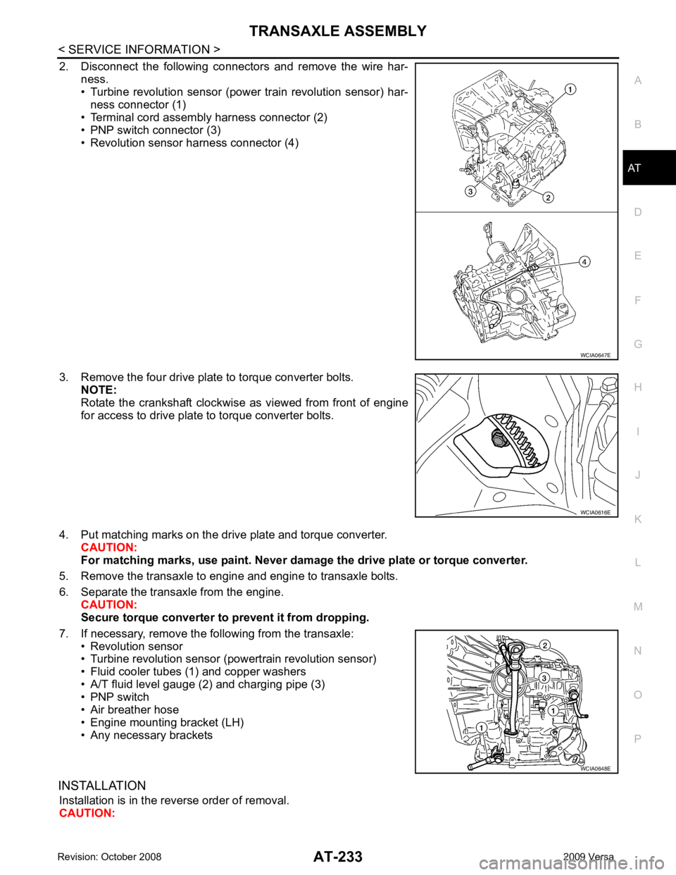
2. Disconnect the following connectors and remove the wire har-
ness.
• Turbine revolution sensor (power train revolution sensor) har-
ness connector (1)
• Terminal cord assembly harness connector (2)
• PNP switch connector (3)
• Revolution sensor harness connector (4)
3. Remove the four drive plate to torque converter bolts. NOTE:
Rotate the crankshaft clockwise as viewed from front of engine
for access to drive plate to torque converter bolts.
4. Put matching marks on the drive plate and torque converter. CAUTION:
For matching marks, use paint. Never dama ge the drive plate or torque converter.
5. Remove the transaxle to engine and engine to transaxle bolts.
6. Separate the transaxle from the engine. CAUTION:
Secure torque converter to prevent it from dropping.
7. If necessary, remove the following from the transaxle: • Revolution sensor
• Turbine revolution sensor (powertrain revolution sensor)
• Fluid cooler tubes (1) and copper washers
• A/T fluid level gauge (2) and charging pipe (3)
• PNP switch
• Air breather hose
• Engine mounting bracket (LH)
• Any necessary brackets
INSTALLATION Installation is in the reverse order of removal.
CAUTION: WCIA0616E
WCIA0648E
Page 812 of 4331
Fluids and Lubricants " .
• Never reuse drained brake fluid.
Front Brake Tube and Hose INFOID:0000000004305896
REMOVAL
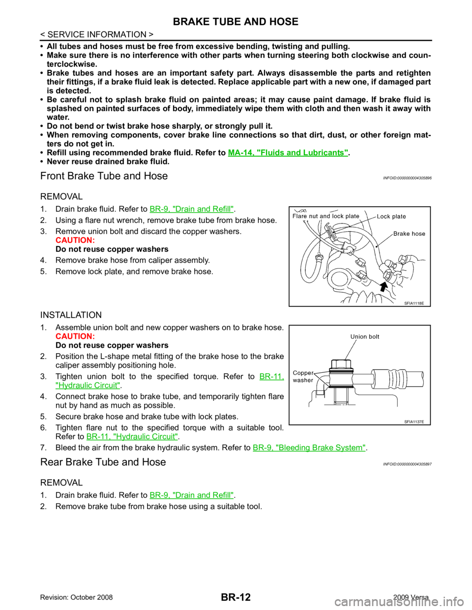
1. Drain brake fluid. Refer to BR-9, " Drain and Refill " .
2. Using a flare nut wrench, remove brake tube from brake hose.
3. Remove union bolt and discard the copper washers. CAUTION:
Do not reuse copper washers
4. Remove brake hose from caliper assembly.
5. Remove lock plate, and remove brake hose.
INSTALLATION
1. Assemble union bolt and new copper washers on to brake hose. CAUTION:
Do not reuse copper washers
2. Position the L-shape metal fitting of the brake hose to the brake caliper assembly positioning hole.
3. Tighten union bolt to the specified torque. Refer to BR-11," Hydraulic Circuit " .
4. Connect brake hose to brake tube, and temporarily tighten flare nut by hand as much as possible.
5. Secure brake hose and brake tube with lock plates.
6. Tighten flare nut to the specified torque with a suitable tool. Refer to BR-11, " Hydraulic Circuit " .
7. Bleed the air from the brake hydraulic system. Refer to BR-9, " Bleeding Brake System " .
Rear Brake Tube and Hose INFOID:0000000004305897
REMOVAL
1. Drain brake fluid. Refer to BR-9, " Drain and Refill " .
2. Remove brake tube from brake hose using a suitable tool.
Page 828 of 4331
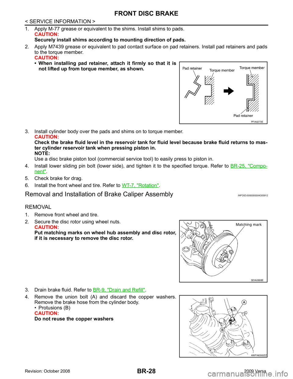
Compo-
nent " .
5. Check brake for drag.
6. Install the front wheel and tire. Refer to WT-7, " Rotation " .
Removal and Installation of Brake Caliper Assembly INFOID:0000000004305912
REMOVAL
1. Remove front wheel and tire.
2. Secure the disc rotor using wheel nuts. CAUTION:
Put matching marks on wheel hub assembly and disc rotor,
if it is necessary to remove the disc rotor.
3. Drain brake fluid. Refer to BR-9, " Drain and Refill " .
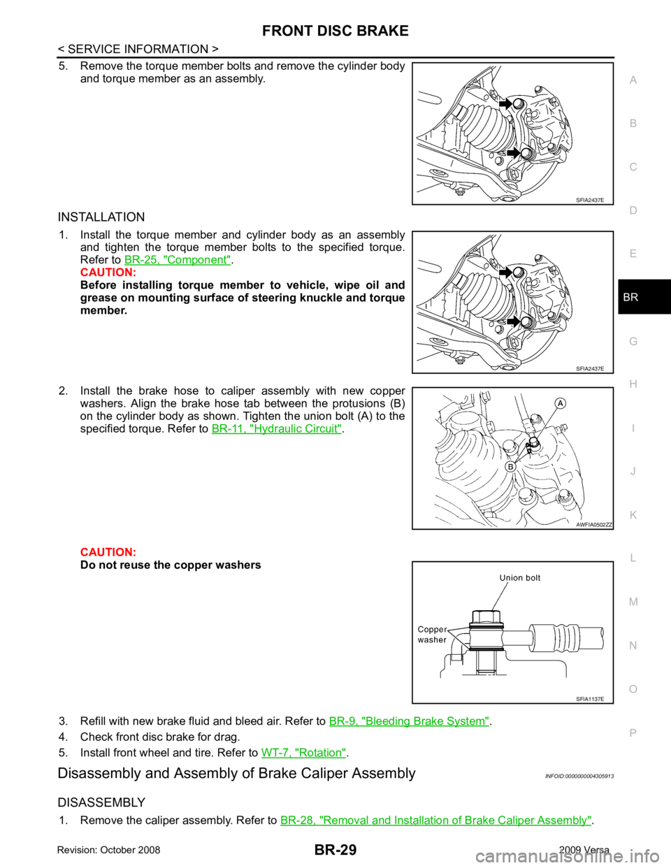
4. Remove the union bolt (A) and discard the copper washers. Remove the brake hose from the cylinder body.
• Protusions (B)
CAUTION:
Do not reuse the copper washers AWFIA0502ZZ
Page 829 of 4331
BR
N
O P
5. Remove the torque member bolts and remove the cylinder body
and torque member as an assembly.
INSTALLATION 1. Install the torque member and cylinder body as an assembly and tighten the torque member bolts to the specified torque.
Refer to BR-25, " Component " .
CAUTION:
Before installing torque member to vehicle, wipe oil and
grease on mounting surface of steering knuckle and torque
member.
2. Install the brake hose to caliper assembly with new copper washers. Align the brake hose tab between the protusions (B)
on the cylinder body as shown. Tighten the union bolt (A) to the
specified torque. Refer to BR-11, " Hydraulic Circuit " .
CAUTION:
Do not reuse the copper washers
3. Refill with new brake fluid and bleed air. Refer to BR-9, " Bleeding Brake System " .
4. Check front disc brake for drag.
5. Install front wheel and tire. Refer to WT-7, " Rotation " .
Disassembly and Assembly of Brake Caliper Assembly INFOID:0000000004305913
DISASSEMBLY 1. Remove the caliper assembly. Refer to BR-28, " Removal and Installation of Brake Caliper Assembly " .AWFIA0502ZZ
SFIA1137E
Page 1126 of 4331
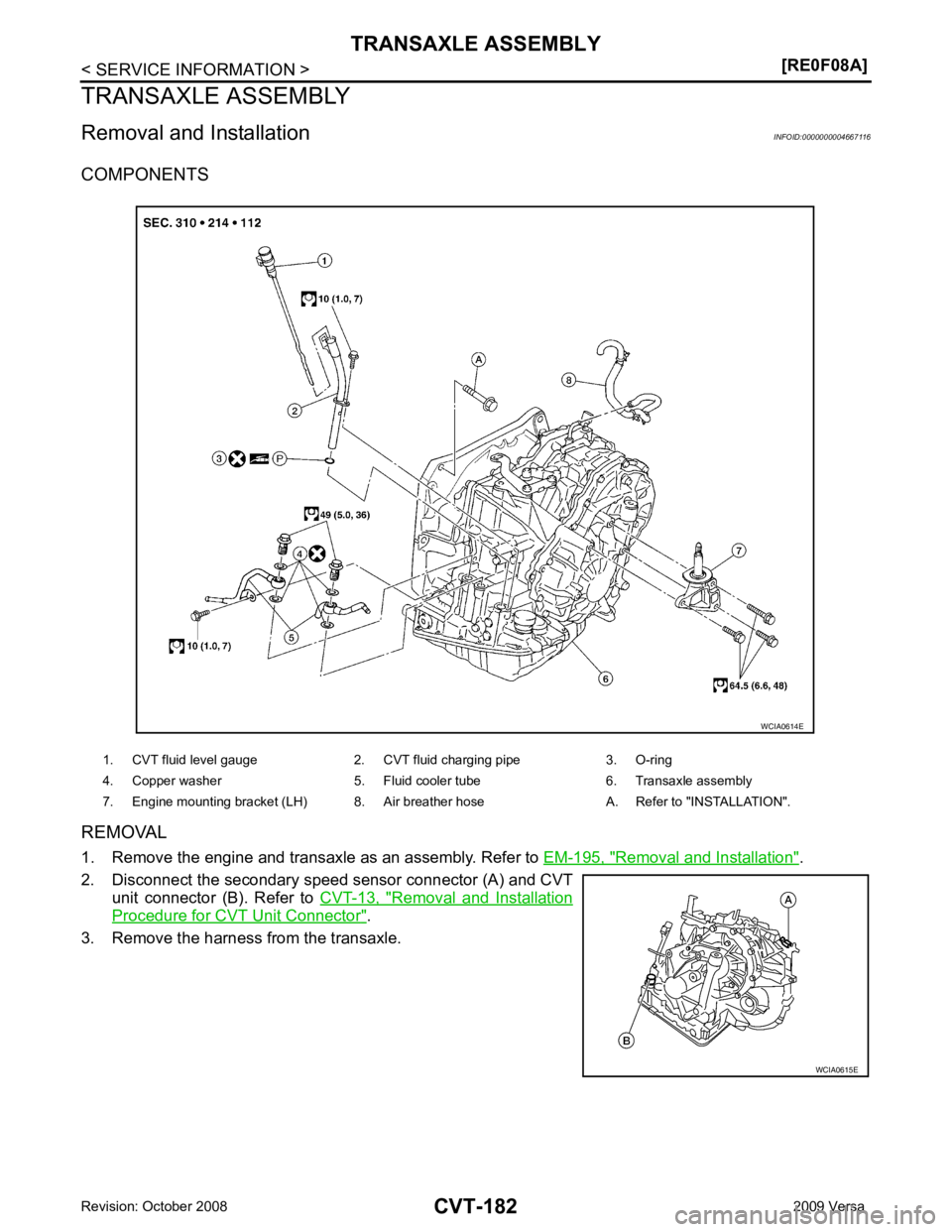
Removal and Installation " .
2. Disconnect the secondary speed sensor connector (A) and CVT unit connector (B). Refer to CVT-13, " Removal and Installation
Procedure for CVT Unit Connector " .
3. Remove the harness from the transaxle. 1. CVT fluid level gauge 2. CVT fluid charging pipe 3. O-ring
4. Copper washer 5. Fluid cooler tube 6. Transaxle assembly
7. Engine mounting bracket (LH) 8. Air breather hose A. Refer to "INSTALLATION". WCIA0615E
Page 1127 of 4331
![NISSAN LATIO 2009 Service Repair Manual TRANSAXLE ASSEMBLY
CVT-183
< SERVICE INFORMATION >
[RE0F08A] D
E
F
G H
I
J
K L
M A
B CVT
N
O P
4. Remove the four drive plate to torque converter nuts.
NOTE:
Rotate the crankshaft clockwise as vi NISSAN LATIO 2009 Service Repair Manual TRANSAXLE ASSEMBLY
CVT-183
< SERVICE INFORMATION >
[RE0F08A] D
E
F
G H
I
J
K L
M A
B CVT
N
O P
4. Remove the four drive plate to torque converter nuts.
NOTE:
Rotate the crankshaft clockwise as vi](/manual-img/5/57359/w960_57359-1126.png)
TRANSAXLE ASSEMBLY
CVT-183
< SERVICE INFORMATION >
[RE0F08A] D
E
F
G H
I
J
K L
M A
B CVT
N
O P
4. Remove the four drive plate to torque converter nuts.
NOTE:
Rotate the crankshaft clockwise as viewed from front of engine
for access to drive plate to torque converter nuts.
5. Put matching marks on the drive plate and torque converter alignment stud. CAUTION:
For matching marks, use paint. Never dama ge the drive plate or torque converter.
6. Remove the transaxle to engine and engine to transaxle bolts.
7. Separate the transaxle from the engine.
8. If necessary, remove the following from the transaxle: • CVT fluid charging pipe
• Engine mounting bracket (LH)
• Fluid cooler tubes
• Air breather hose
• Any necessary brackets
INSTALLATION Installation is in the reverse order of removal.
CAUTION:
• When replacing an engine or transmission you mu st make sure any dowels are installed correctly
during re-assembly.
• Improper alignment caused by missing dowels m ay cause vibration, oil leaks or breakage of drive
train components.
• Do not reuse O-rings and copper washers.
• When turning crankshaft, turn it clockwise as viewed from the front of the engine.
• When tightening the nuts for the torque converter while securing the crankshaft pulley bolt, be sure
to confirm the tightening torque of the crankshaft pulley bolt. Refer to EM-160 .
• After converter is installed to drive plate, ro tate crankshaft several turns to check that transaxle
rotates freely without binding.
• When installing the torque converter to the transaxle measure dis- tance A. WCIA0616E
Distance A: 14.4 mm (0.57 in) or more
WCIA0617E