2009 NISSAN LATIO fuel tank removal
[x] Cancel search: fuel tank removalPage 2633 of 4331

DTC P0182, P0183 FTT SENSOR
EC-1277
< SERVICE INFOMATION >
[MR TYPE 2] C
D E
F
G H
I
J
K L
M A EC
NP
O
3. Check harness continuity between “fuel level sens
or unit and fuel pump” terminal 5 and combination
meter terminal 24. Refer to Wiring Diagram.
4. Also check harness for short to ground and short to power.
OK or NG OK >> GO TO 6.
NG >> GO TO 5. 5.
DETECT MALFUNCTIONING PART
Check the following.
• Harness connectors B102, M13
• Harness for open or short between “fuel level sensor unit and fuel pump” and ground.
>> Repair open circuit or short to ground or short to power in harness or connectors. 6.
CHECK FUEL TANK TEMPERATURE SENSOR
Refer to, EC-1277, " Component Inspection " .
OK or NG OK >> GO TO 7.
NG >> Replace “fuel level sensor unit and fuel pump”. 7.
CHECK INTERMITTENT INCIDENT
Perform EC-1138 .
>> INSPECTION END
Component Inspection INFOID:0000000004501182
FUEL TANK TEMPERATURE SENSOR 1. Check resistance between “fuel level sensor unit and fuel pump” terminal 4 and 5 by heating with hot water as shown in the fig-
ure.
2. If NG, replace “fuel level sensor unit and fuel pump”.
Removal and Installation INFOID:0000000004501183
FUEL TANK TEMPERATURE SENSOR Refer to FL-5, " Removal and Installation " .
Continuity should exist.
Temperature °C ( °F) Resistance k Ω
20 (68) 2.3 - 2.7
50 (122) 0.79 - 0.90 PBIB0931E
Page 2740 of 4331

Diagnosis Procedure " .
WITH GST
NOTE:
Start from step 8, if it is possible to confirm that the fuel cannot be drained by 30 (7-7/8 US gal, 6-5/8
Imp gal) in advance.
1. Prepare a fuel container and a spare hose.
2. Release fuel pressure from fuel line, refer to EC-1086, " Fuel Pressure Check " .
3. Remove the fuel feed hose on the fuel level sensor unit.
4. Connect a spare fuel hose where the fuel feed hose was removed.
5. Turn ignition switch ON.
6. Drain fuel by 30 (7-7/8 US gal, 6-5/8 Imp gal) from the fuel tank using proper equipment.
7. Confirm that the fuel gauge indication varies.
8. Fill fuel into the fuel tank for 30 (7-7/8 US gal, 6-5/8 Imp gal).
9. Confirm that the fuel gauge indication varies.
10. If NG, go to EC-1384, " Diagnosis Procedure " .
Diagnosis Procedure INFOID:0000000004501202Self-Diagnosis Mode of Combination Meter " .
OK or NG OK >> GO TO 2.
NG >> Follow the instruction of DI-10, " Self-Diagnosis Mode of Combination Meter " .
Fuel Level Sensor Signal Inspection " .
OK or NG OK >> GO TO 3.
NG >> Repair or replace malfunctioning parts. .
>> INSPECTION END
Removal and Installation INFOID:0000000004501203
FUEL LEVEL SENSOR
Refer to FL-5 .
Page 3036 of 4331
EM
NP
O
• If items or work required are not covered by the
engine section, follow the procedures in the applica-
ble sections.
• Always use the support poin t specified for lifting.
• Use either 2-pole lift type or separate type lift as best you can. If board-on type is used for unavoid-
able reasons, support at the rear axle jacking point with a transmission jack or similar tool before
starting work, in prepar ation for the backward shif t of center of gravity.
• For supporting points fo r lifting and jacking point at rear axle, refer to GI-38, " Garage Jack and
Safety Stand and 2-Pole Lift " .
REMOVAL
Outline Remove the engine and the transaxle assembly from t he vehicle downward. Separate the engine and the tran-
saxle.
Preparation 1. Remove the hood assembly. Refer to BL-14, " Removal and Installation " .
2. Remove the cowl top cover and cowl top extension assembly. Refer to EI-22, " Removal and Installation " .
3. Release fuel pressure. Refer to EC-498, " Inspection " .
4. Drain engine coolant from radiator. Refer to CO-11, " Changing Engine Coolant " .
CAUTION:
• Perform this step when the engine is cold.
• Never spill engine coolant on drive belt.
5. Drain the transmission fluid. Refer to MT-10, " Draining " (M/T),
AT-17, " Changing A/T Fluid " (A/T).
6. Remove the following parts. • Engine undercover
• Front road wheels and tires: Refer to WT-7, " Rotation " .
• Front fender protector (RH and LH): Refer to EI-24, " Removal and Installation " .
• Battery and battery tray: Refer to SC-7, " Removal and Installation " .
• Drive belt: Refer to EM-15, " Removal and Installation " .
• Air duct and air cleaner case assembly: Refer to EM-26, " Exploded View " .
• Radiator hose (upper and lower): Refer to CO-16, " Component " .
• Disconnect cooling fan controller wiring harness.
• Remove coolant reservoir tank.
• Remove fan shroud and cooling fan assembly. Refer to CO-18, " Component (Models with A/C) " or
CO- 18, " Component (Models without A/C) " .
Engine Room LH 1. Disconnect all connections of engine harness around the engine mounting insulator (LH), and then tem- porarily secure the engine harness into the engine side.
CAUTION:
Protect connectors using a resin bag against foreign materials.
2. Remove ground cable at transaxle side.
3. Disconnect fuel feed hose at engine side. Refer to EM-34, " Exploded View " .
4. Disconnect EVAP purge hose and brake booster vacuum hose.
5. Disconnect heater hoses, and install plugs them to prevent engine coolant from draining. Refer to CO-16," Component " .
6. Disconnect control linkage from transaxle. Refer to AT-212, " Control Device Removal and Installation " (A/
T), MT-13, " Exploded View " (M/T).
7. Disconnect the clutch tube at tr ansmission side (if equipped). Refer to CL-14, " Removal and Installation " .
Engine Room RH 1. Remove ground cable between front cover and vehicle.
2. Remove generator and generator bracket; Refer to SC-25, " Removal and Installation " .
3. Remove A/C compressor with piping connected from t he engine. Temporarily secure it on the vehicle side
with a rope to avoid putting load on it. (if equipped) Refer to MTC-78, " Removal and Installation of Com-
pressor - HR16DE " .
Vehicle Underbody
Page 3221 of 4331
FL
N
O P
CONTENTS
FUEL SYSTEM
SERVICE INFORMATION .. ..........................2
PRECAUTIONS .............................................. .....2
Precaution for Supplemental Restraint System
(SRS) "AIR BAG" and "SEAT BELT PRE-TEN-
SIONER" ............................................................. ......
2
PREPARATION .............................................. .....3
Special Service Tool ........................................... ......3
Commercial Service Tool .................................... ......3
FUEL SYSTEM ............................................... .....4
Checking Fuel Line ............................................. ......4
General Precaution ............................................. ......4 FUEL LEVEL SENSOR UNIT, FUEL FILTER
AND FUEL PUMP ASSEMBLY ......................... 5
Component .......................................................... .....5
Removal and Installation ..................................... .....5
FUEL TANK ..... ................................ ..................9
Component .......................................................... .....9
Removal and Installation ..................................... .....9
SERVICE DATA AND SPECIFICATIONS
(SDS) ................................................................. 14
Standard and Limit .............................................. ....14
Page 3225 of 4331
FL
NP
O
FUEL LEVEL SENSOR UNIT, FUEL FI
LTER AND FUEL PUMP ASSEMBLY
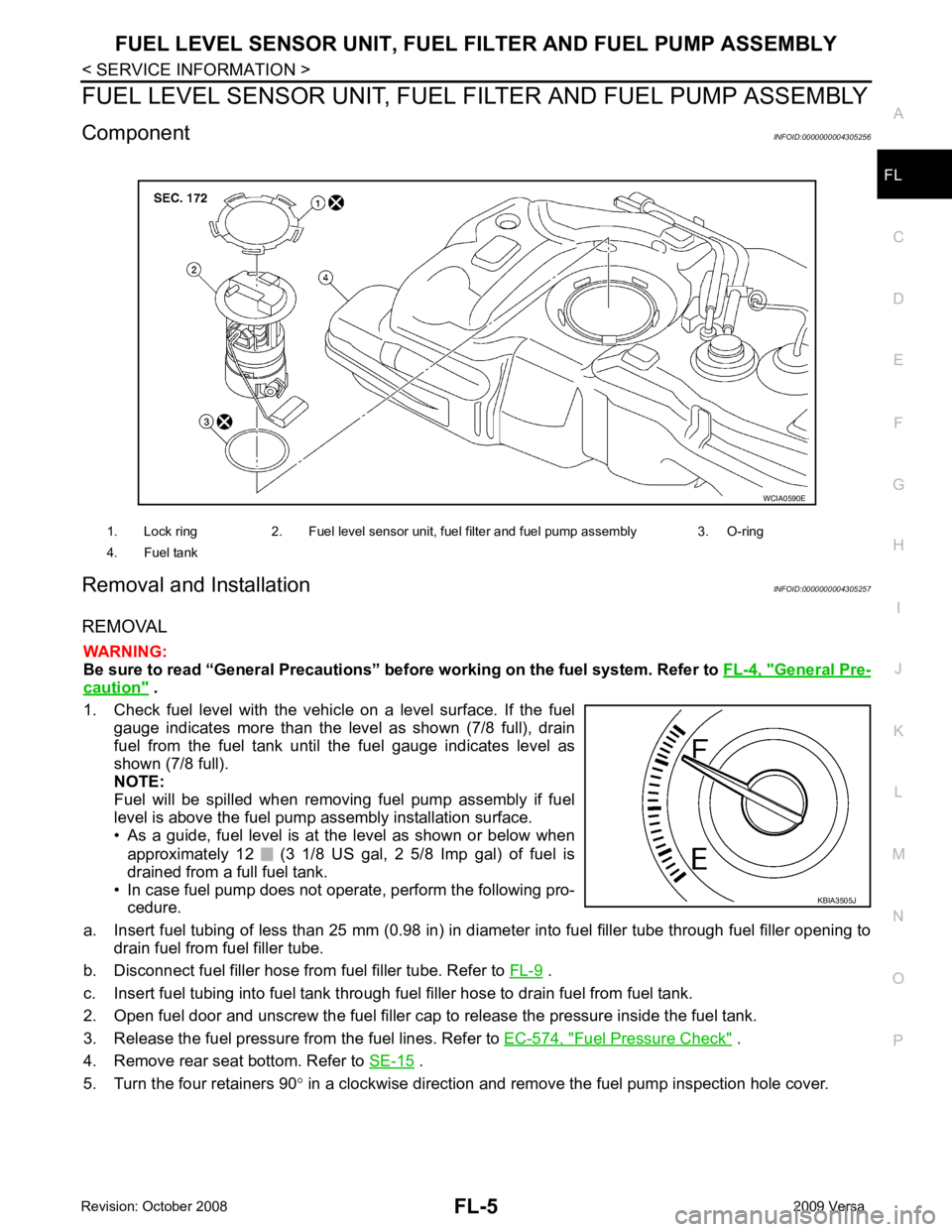
Component INFOID:0000000004305256
Removal and Installation INFOID:0000000004305257
REMOVAL WARNING:
Be sure to read “General Precautions” be fore working on the fuel system. Refer to FL-4, " General Pre-
caution " .
1. Check fuel level with the vehicle on a level surface. If the fuel gauge indicates more than the level as shown (7/8 full), drain
fuel from the fuel tank until the fuel gauge indicates level as
shown (7/8 full).
NOTE:
Fuel will be spilled when removing fuel pump assembly if fuel
level is above the fuel pump assembly installation surface.
• As a guide, fuel level is at the level as shown or below when
approximately 12 (3 1/8 US gal, 2 5/8 Imp gal) of fuel is
drained from a full fuel tank.
• In case fuel pump does not operate, perform the following pro- cedure.
a. Insert fuel tubing of less than 25 mm (0.98 in) in di ameter into fuel filler tube through fuel filler opening to
drain fuel from fuel filler tube.
b. Disconnect fuel filler hose from fuel filler tube. Refer to FL-9 .
c. Insert fuel tubing into fuel tank through fuel filler hose to drain fuel from fuel tank.
2. Open fuel door and unscrew the fuel filler cap to release the pressure inside the fuel tank.
3. Release the fuel pressure from the fuel lines. Refer to EC-574, " Fuel Pressure Check " .
4. Remove rear seat bottom. Refer to SE-15 .
5. Turn the four retainers 90 ° in a clockwise direction and remove the fuel pump inspection hole cover.
1. Lock ring 2. Fuel level sensor unit, fuel filter and fuel pump assembly 3. O-ring
4. Fuel tank
Page 3227 of 4331
FL
NP
O
Make sure that the fuel level sensor
unit, fuel filter and fuel pump is free from defects and foreign materials.
INSTALLATION Installation is in the reverse order of removal.
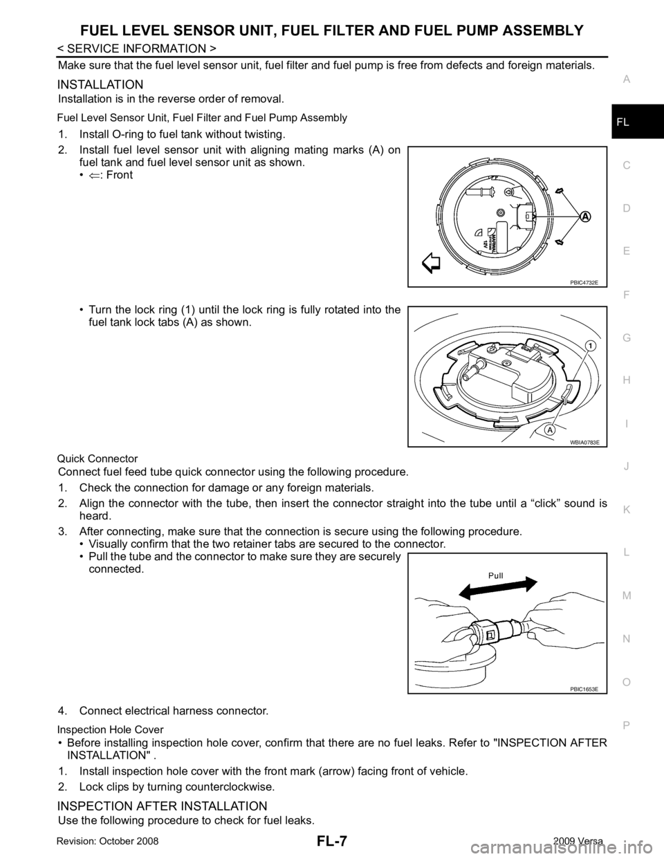
Fuel Level Sensor Unit, Fuel Filter and Fuel Pump Assembly 1. Install O-ring to fuel tank without twisting.
2. Install fuel level sensor unit with aligning mating marks (A) on fuel tank and fuel level sensor unit as shown.
• ⇐ : Front
• Turn the lock ring (1) until the lock ring is fully rotated into the fuel tank lock tabs (A) as shown.
Quick Connector Connect fuel feed tube qui ck connector using the following procedure.
1. Check the connection for damage or any foreign materials.
2. Align the connector with the tube, then insert the c onnector straight into the tube until a “click” sound is
heard.
3. After connecting, make sure that the connection is secure using the following procedure. • Visually confirm that the two retainer tabs are secured to the connector.
• Pull the tube and the connector to make sure they are securely connected.
4. Connect electrical harness connector.
Inspection Hole Cover • Before installing inspection hole cover, confirm that there are no fuel leaks. Refer to "INSPECTION AFTER
INSTALLATION" .
1. Install inspection hole cover with the front mark (arrow) facing front of vehicle.
2. Lock clips by turning counterclockwise.
INSPECTION AFTER INSTALLATION Use the following procedure to check for fuel leaks. WBIA0783E
PBIC1653E
Page 3229 of 4331
FL
NP
O
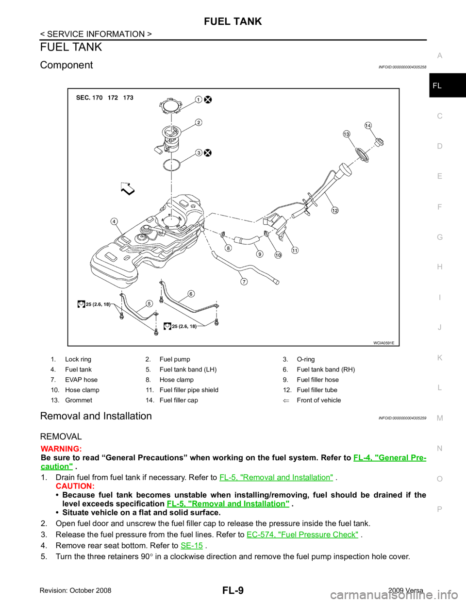
FUEL TANK
Component INFOID:0000000004305258
Removal and Installation INFOID:0000000004305259
REMOVAL WARNING:
Be sure to read “General Precautions” wh en working on the fuel system. Refer to FL-4, " General Pre-
caution " .
1. Drain fuel from fuel tank if necessary. Refer to FL-5, " Removal and Installation " .
CAUTION:
• Because fuel tank becomes unstable when instal ling/removing, fuel should be drained if the
level exceeds specification FL-5, " Removal and Installation " .
• Situate vehicle on a flat and solid surface.
2. Open fuel door and unscrew the fuel filler cap to release the pressure inside the fuel tank.
3. Release the fuel pressure from the fuel lines. Refer to EC-574, " Fuel Pressure Check " .
4. Remove rear seat bottom. Refer to SE-15 .
5. Turn the three retainers 90 ° in a clockwise direction and remove the fuel pump inspection hole cover.
1. Lock ring 2. Fuel pump 3. O-ring
4. Fuel tank 5. Fuel tank band (LH) 6. Fuel tank band (RH)
7. EVAP hose 8. Hose clamp 9. Fuel filler hose
10. Hose clamp 11. Fuel filler pipe shield 12. Fuel filler tube
13. Grommet 14. Fuel filler cap ⇐Front of vehicle
Page 3230 of 4331
FL-10< SERVICE INFORMATION >
FUEL TANK
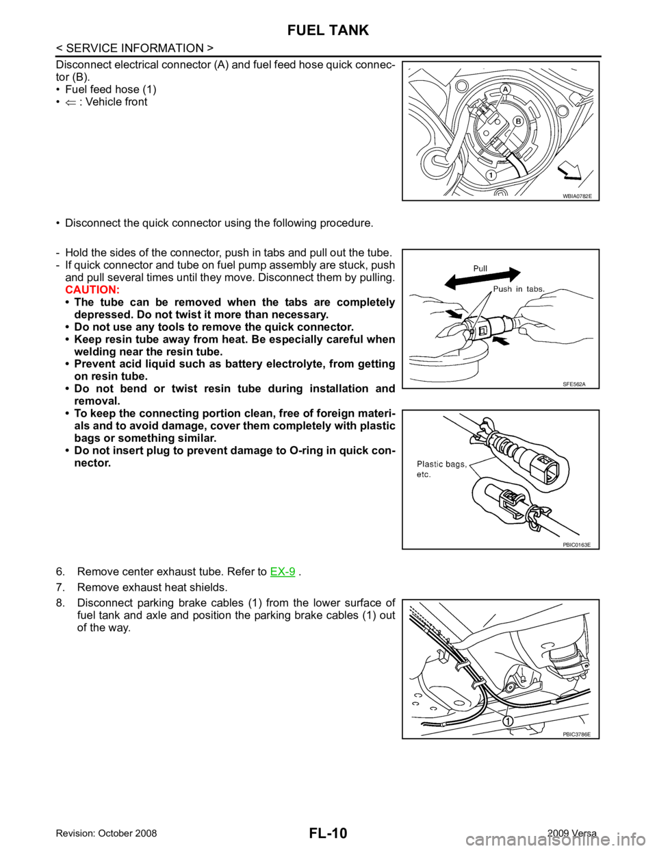
Disconnect electrical connector (A) and fuel feed hose quick connec-
tor (B).
• Fuel feed hose (1)
• ⇐ : Vehicle front
• Disconnect the quick connector using the following procedure.
- Hold the sides of the connector, push in tabs and pull out the tube.
- If quick connector and tube on fuel pump assembly are stuck, push
and pull several times until they move. Disconnect them by pulling.
CAUTION:
• The tube can be removed when the tabs are completely depressed. Do not twist it more than necessary.
• Do not use any tools to remove the quick connector.
• Keep resin tube away from h eat. Be especially careful when
welding near the resin tube.
• Prevent acid liquid such as ba ttery electrolyte, from getting
on resin tube.
• Do not bend or twist resin tube during installation and removal.
• To keep the connecting portion clean, free of foreign materi-
als and to avoid damage, cover them completely with plastic
bags or something similar.
• Do not insert plug to prevent damage to O-ring in quick con-
nector.
6. Remove center exhaust tube. Refer to EX-9 .
7. Remove exhaust heat shields.
8. Disconnect parking brake cables (1) from the lower surface of
fuel tank and axle and position the parking brake cables (1) out
of the way. WBIA0782E
SFE562A
PBIC0163E
PBIC3786E